Knuckle Coupler
ProductAlso known as: AAR coupler, Janney coupler, railroad coupler, knuckle coupling
Overview
The knuckle coupler, also called the Janney coupler or AAR automatic coupler, is the standard end-of-car coupling on North American freight and many passenger railcars. It replaced manual link-and-pin coupling, which required a worker to stand between cars to drop a pin by hand. The knuckle coupler couples automatically when two cars are pushed together: the rotating jaws (knuckles) close over one another and an internal lock drops by gravity to hold them shut.
A complete coupler installation is more than the visible head. It includes the Coupler head and its Coupler shank, the Friction draft gear that cushions buff and draft shocks, the Yoke assembly that ties the coupler to the draft gear, the Center sill draft pocket machined into the car center sill, the Striker casting, the Coupler carrier that holds the coupler up, and the Uncoupling rig worked from the side of the car. The whole assembly is AAR Grade E cast steel in current practice, with an ultimate strength near 3000 kN.
Coupler head and knuckle
The Coupler body is a single steel casting forming the guard arm, the throat, and the pulling lug. The Knuckle is the moving jaw, pivoting on a vertical Knuckle pin retained at top and bottom by a Knuckle pin retainer. When two couplers meet, each open knuckle is pushed closed by the mating coupler nose; in the closed position the knuckles interlock so that tension pulls them tighter rather than apart.
The Gathering wing surfaces on the guard arm taper inward so that couplers offset by up to roughly 100 mm are steered into alignment as the cars come together. This gathering range is what lets cars couple on curves and over humps without manual lining up. Two replaceable plates protect the casting from wear: the Contour wear plate at the pulling face and the Gauge wear plate at the knuckle nose, which keeps the coupling contour within gauge as the steel wears.
Locking mechanism
Inside the head, the Lock assembly holds the knuckle closed. The Lock is a heavy block that drops behind the tail of the knuckle once the knuckle rotates to the closed position, blocking it from opening under load. The Anti-creep shelf is an internal ledge that stops the lock from creeping upward as the coupler is repeatedly loaded in buff and draft, which is the condition that allowed older designs to release on their own.
Uncoupling is done without going between the cars. Raising the Cut lever turns the Rotary lock lift (a rotary cam) on its Lock lift pin, which lifts the lock clear of the knuckle tail. The same motion drives the Knuckle thrower, a lever that rotates the knuckle to the open position so the cars can be pulled apart. The Locking-set lever then holds the lock set back so the coupler stays open and ready until it next couples.
Draft gear and yoke
Buff (compression) and draft (tension) shocks during coupling and train handling are absorbed by the Friction draft gear, a friction-spring unit mounted in the center sill pocket. Inside the Draft gear housing, a Center wedge driven by the Draft gear follower spreads a set of Friction wedge shoe shoes outward against Friction plate surfaces. The wedges turn axial travel into friction, while the spring package (modeled here as Coil Spring elements seated on Spring seat plates) stores and returns energy. A Release spring returns the friction elements after each cycle. Capacity ranges from about 250 kN for light service to 1400 kN for high-capacity units, with 60 to 90 mm of travel.
Tension loads do not pass through the draft gear directly. They go through the Yoke assembly: the Yoke straddles the draft gear, its front end pinned to the coupler by the Coupler key through the Key slot bushing in the shank, its rear bearing on the Rear draft lug castings. The Key retainer keeps the key from working out. In buff, the Coupler horn on the shank bears against the Striker casting and the Shank butt presses the follower into the draft gear, which reacts against the Front draft lug.
Mounting and uncoupling
The coupler is carried at the correct height by the Coupler carrier. The Carrier iron sits under the shank with a Carrier wear plate at the contact point, and a Carrier pivot pin lets the coupler swing laterally so cars can negotiate curves. The Striker body at the front of the Center sill draft pocket takes the buff impacts through a replaceable Striker wear plate and limits coupler travel with its Coupler stop faces. The draft pocket itself is part of the Center sill section, with Front draft lug and Rear draft lug castings secured by the Draft lug fastening set and protected by Pocket wear plate liners.
The Uncoupling rig is the operator interface. The Cut lever runs across the end of the car on Cut lever bracket supports, ending in a Cut lever handle reachable from the side. An Uncoupling chain and Uncoupling rod connect the lever to the lock lift, so one pull from a safe position opens the coupler. This side operation, together with automatic coupling on impact, is why the knuckle coupler displaced the older link-and-pin system that put workers between moving cars.
Knuckle Coupler parts and their functions
8 top-level parts · 63 parts in total · full bill of materials below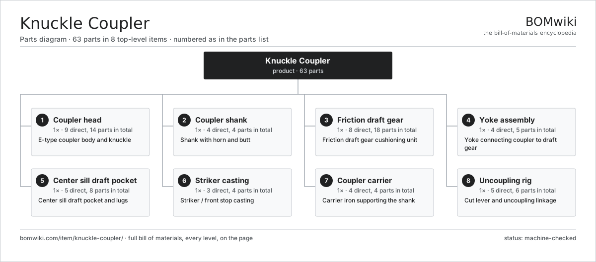
| # | Part | Qty | What it does |
|---|---|---|---|
| 1 | Coupler head 9 parts | 1× | E-type coupler body and knuckle |
| 2 | Coupler shank 4 parts | 1× | Shank with horn and butt |
| 3 | Friction draft gear 8 parts | 1× | Friction draft gear cushioning unit |
| 4 | Yoke assembly 4 parts | 1× | Yoke connecting coupler to draft gear |
| 5 | Center sill draft pocket 5 parts | 1× | Center sill draft pocket and lugs |
| 6 | Striker casting 3 parts | 1× | Striker / front stop casting |
| 7 | Coupler carrier 4 parts | 1× | Carrier iron supporting the shank |
| 8 | Uncoupling rig 5 parts | 1× | Cut lever and uncoupling linkage |
Diagrams & photos

3D model
No 3D model yet. Have a CAD file of this? Add a 3D model. STL renders right on this page; STEP, FreeCAD, and OpenSCAD sources are welcome too (openly licensed, like all 3D models on BOMwiki).
Build & assembly graph
expand / collapse · shared sub-assemblies converge · links to related products · est. labourTap an assembly to expand/collapse · tap a part to open it · use “Open page” for any node · drag to pan, scroll to zoom.
Bill of materials for Knuckle Coupler
8 top-level lines · 56 rows shown · 63 parts total · indented to 3 levels| # | Item / sub-assembly | Part no. | Qty/assy | Ext. qty | Parts | Type |
|---|---|---|---|---|---|---|
| 1 | Coupler head 9 parts | kc-coupler-head | 1× | 1 | 14 | assembly |
| 1.1 | Coupler body | kc-coupler-body | 1× | 1 | · | part |
| 1.2 | Knuckle | kc-knuckle | 1× | 1 | · | part |
| 1.3 | Knuckle pin | kc-knuckle-pin | 1× | 1 | · | part |
| 1.4 | Knuckle thrower 2 parts | kc-knuckle-thrower | 1× | 1 | 2 | assembly |
| 1.4.1 | Thrower casting | kc-thrower-casting | 1× | 1 | · | part |
| 1.4.2 | Thrower pivot pin | kc-thrower-pin | 1× | 1 | · | part |
| 1.5 | Lock assembly 4 parts | kc-lock-assembly | 1× | 1 | 4 | assembly |
| 1.5.1 | Lock | kc-lock | 1× | 1 | · | part |
| 1.5.2 | Rotary lock lift | kc-lock-lift | 1× | 1 | · | part |
| 1.5.3 | Lock lift pin | kc-lock-pin | 1× | 1 | · | part |
| 1.5.4 | Locking-set lever | kc-lockset-lever | 1× | 1 | · | part |
| 1.6 | Anti-creep shelf | kc-anti-creep-shelf | 1× | 1 | · | part |
| 1.7 | Gathering wing | kc-gathering-wing | 2× | 2 | · | part |
| 1.8 | Contour wear plate | kc-contour-wear-plate | 1× | 1 | · | part |
| 1.9 | Gauge wear plate | kc-gauge-wear-plate | 1× | 1 | · | part |
| 2 | Coupler shank 4 parts | kc-coupler-shank | 1× | 1 | 4 | assembly |
| 2.1 | Shank casting | kc-shank-casting | 1× | 1 | · | part |
| 2.2 | Coupler horn | kc-coupler-horn | 1× | 1 | · | part |
| 2.3 | Shank butt | kc-shank-butt | 1× | 1 | · | part |
| 2.4 | Key slot bushing | kc-key-slot-bushing | 1× | 1 | · | part |
| 3 | Friction draft gear 8 parts | kc-draft-gear | 1× | 1 | 18 | assembly |
| 3.1 | Draft gear housing | kc-draft-gear-housing | 1× | 1 | · | part |
| 3.2 | Friction wedge shoe | kc-friction-wedge | 3× | 3 | · | part |
| 3.3 | Friction plate | kc-friction-plate | 3× | 3 | · | part |
| 3.4 | Center wedge | kc-center-wedge | 1× | 1 | · | part |
| 3.5 | Coil Spring | coil-spring | 6× | 6 | · | part |
| 3.6 | Spring seat | kc-spring-seat | 2× | 2 | · | part |
| 3.7 | Draft gear follower | kc-draft-gear-follower | 1× | 1 | · | part |
| 3.8 | Release spring | kc-release-spring | 1× | 1 | · | part |
| 4 | Yoke assembly 4 parts | kc-yoke-assembly | 1× | 1 | 5 | assembly |
| 4.1 | Yoke | kc-yoke | 1× | 1 | · | part |
| 4.2 | Coupler key | kc-yoke-key | 1× | 1 | · | part |
| 4.3 | Key retainer | kc-yoke-key-retainer | 1× | 1 | · | part |
| 4.4 | Yoke strap wear plate | kc-yoke-strap-wear-plate | 2× | 2 | · | part |
| 5 | Center sill draft pocket 5 parts | kc-draft-pocket | 1× | 1 | 8 | assembly |
| 5.1 | Center sill section | kc-center-sill-section | 1× | 1 | · | part |
| 5.2 | Front draft lug | kc-front-draft-lug | 2× | 2 | · | part |
| 5.3 | Rear draft lug | kc-rear-draft-lug | 2× | 2 | · | part |
| 5.4 | Draft lug fastening set | kc-draft-lug-rivets | 1× | 1 | · | part |
| 5.5 | Pocket wear plate | kc-pocket-wear-plate | 2× | 2 | · | part |
| 6 | Striker casting 3 parts | kc-striker-casting | 1× | 1 | 4 | assembly |
| 6.1 | Striker body | kc-striker-body | 1× | 1 | · | part |
| 6.2 | Striker wear plate | kc-striker-wear-plate | 1× | 1 | · | part |
| 6.3 | Coupler stop | kc-coupler-stop | 2× | 2 | · | part |
| 7 | Coupler carrier 4 parts | kc-coupler-carrier | 1× | 1 | 4 | assembly |
| 7.1 | Carrier iron | kc-carrier-iron | 1× | 1 | · | part |
| 7.2 | Carrier wear plate | kc-carrier-wear-plate | 1× | 1 | · | part |
| 7.3 | Carrier pivot pin | kc-carrier-pivot-pin | 1× | 1 | · | part |
| 7.4 | Fastener Set | fastener-set | 1× | 1 | · | part |
| 8 | Uncoupling rig 5 parts | kc-uncoupling-rig | 1× | 1 | 6 | assembly |
| 8.1 | Cut lever | kc-cut-lever | 1× | 1 | · | part |
| 8.2 | Cut lever bracket | kc-cut-lever-bracket | 2× | 2 | · | part |
| 8.3 | Uncoupling chain | kc-uncoupling-chain | 1× | 1 | · | part |
| 8.4 | Uncoupling rod | kc-uncoupling-rod | 1× | 1 | · | part |
| 8.5 | Cut lever handle | kc-lever-handle | 1× | 1 | · | part |
Related products
same domain, ranked by shared parts Airport Apron Bus
759 parts · shares 1 with this page
Airport Apron Bus
759 parts · shares 1 with this page
 Auto-Rack Railcar
522 parts · shares 1 with this page
Auto-Rack Railcar
522 parts · shares 1 with this page
 Automated People Mover
450 parts · shares 1 with this page
Autorack Wagon
217 parts · shares 1 with this page
Automated People Mover
450 parts · shares 1 with this page
Autorack Wagon
217 parts · shares 1 with this page
 Ballast Regulator
234 parts · shares 1 with this page
Ballast Regulator
234 parts · shares 1 with this page
 Boxcar
256 parts · shares 1 with this page
Boxcar
256 parts · shares 1 with this page
Sourcing: possible vendors
Browse the supplier directory → Prices, MOQ, and lead times are algorithmic estimates, not quotes, and not claims about these companies. Company mappings are curated by keyword; est. price band $500k–$60M. How estimates work| Vendor | HQ | Specialty | MOQ | Lead time |
|---|---|---|---|---|
|
🇨🇳CRRC
crrcgc.cc ↗
|
Beijing, CN | Rolling stock & rail systems | made to order | 40–72 wks |
|
🇫🇷Alstom
alstom.com ↗
|
Saint-Ouen, FR | Rail rolling stock | made to order | 40–72 wks |
| mobility.siemens.com ↗ | Munich, DE | Rail systems | made to order | 40–72 wks |
| stadlerrail.com ↗ | Bussnang, CH | Rail rolling stock | made to order | 40–72 wks |
|
🇺🇸Wabtec
wabteccorp.com ↗
|
Pittsburgh, US | Rail equipment | made to order | 40–72 wks |
935-word article