Transit Bus
ProductOverview
A low-floor transit bus is built for one job: moving large numbers of passengers along a fixed urban route with short stop spacing, fast boarding, and step-free access. The standard form is a two-axle rigid vehicle about 12 m long and 2.55 m wide, carrying roughly 30 seated and 50 standing passengers. What separates it from a coach is the floor. The front and centre of the saloon sit only 320–340 mm above the road, low enough that a passenger steps on at kerb level without a stair. That single requirement reshapes the chassis, the axles, and the way the engine is packaged, and most of the engineering in the Body and Chassis and Driveline and Axles exists to defend it.
The operating cycle is the opposite of long-distance driving. The bus accelerates from rest, runs a few hundred metres, brakes to a stop, opens its doors, and repeats this dozens of times an hour. Dwell time, the seconds spent stationary at each stop while passengers board and alight, is the figure that determines route capacity, so the Door Systems, the kneeling Air Suspension, and the wide flat aisle are all aimed at emptying and filling the bus quickly.
Structure and the low floor
The body is a welded space-frame, the Body Skeleton, usually built from stainless or corrosion-resistant steel tube so it survives road salt over a 12 to 16 year service life. External Body Panels are bonded or bolted on and carry little load, which lets a depot replace a panel after kerb or collision damage without touching the cage. A molded Front Mask and a hinged Rear Mask in glass-reinforced plastic cap the ends, and a light Roof Shell shell carries the rooftop equipment.
The Low-Floor Underframe is where the low floor is created. The structure is stepped: a deep low section over the front and centre, and a raised platform over the rear axle where the engine and driven axle sit. The Floor Panel lies directly on this underframe, and Wheel Arch Box boxes intrude into the saloon, which is why the seats over the wheels sit on raised plinths.
Rear engine and portal axle
Putting the floor that low leaves no room for a conventional driveline under the centre of the bus, so the Powertrain is pushed to the back. The Engine, a 6 to 9 litre diesel or spark-ignition CNG unit of about 180–235 kW, is mounted transversely in a rear corner tower, driving a fully automatic Automatic Transmission with an integral Hydraulic Retarder. The automatic suits stop-start work, and the retarder takes most of the braking energy at speed so the friction brakes wear slowly.
The rear axle is the other half of the solution. A normal drive axle has its differential and tube on the wheel centreline, which would push a hump down the aisle. The Rear Portal Axle instead uses a Portal Gearset at each hub, a drop-gear set that places the wheel centre below the axle tube. Raising the tube clears a continuous low floor right across the rear platform while still driving the wheels. The penalty is added gearing, weight, and oil to maintain, accepted because nothing else gives a driven low floor. The front Front Axle is built slim and low for the same reason.
Suspension, kneeling, and brakes
The bus rides on rolling-lobe Air Spring springs at every wheel rather than steel. Air suspension serves accessibility as much as comfort: the ECAS Controller holds a constant ride height as the load swings between empty and 80 passengers, and at a stop it vents the kerb-side bellows to kneel the bus, dropping the entrance another 60–80 mm so the gap to the kerb is almost flat. Combined with a flip-out ramp at the Centre Door, that lets a wheelchair or pram roll straight on.
Braking is full-air, with a ventilated Disc Brake at each wheel actuated by a Brake Chamber. The ABS/EBS Controller modulates each wheel against lock-up and blends the friction brakes with the transmission retarder so most stops are handled without the pads. An engine-driven Air Compressor and Air Dryer keep the reservoirs charged for brakes, suspension, and door drives.
Doors, interior, and dwell time
A city bus lives or dies on dwell time, so it carries wide Door Systems. The Front Door is for boarding past the Fare Validator, and the centre door for alighting, each driven by a Door Drive that reverses on a Door Edge Sensor obstruction. Overhead Passenger Counter units track occupancy at each door. Inside, fixed Seat Assembly units, a dense Grab Rail System layout for standees, and slip-resistant Floor Covering make up the saloon, with the driver working behind a Driver Protection Screen. A Passenger Information System drives the Destination Sign and next-stop announcements, fed location from the Telematics Unit unit. The HVAC rooftop pack and Saloon Heater units have to cope with doors opening to the street every minute or two.
Electrical architecture and variants
The bus runs a 24 V system around a multiplex Body Controller on a vehicle data bus, which replaces the old loom of relays and discrete wires with addressable modules driving lights, doors, kneeling, and signs. The same bus carries the CCTV System and diagnostics that the depot reads remotely. The platform is offered in several driveline variants on a common body. Diesel remains the baseline; CNG buses move the fuel store to roof cylinders and add a spark-ignition engine; series-hybrid versions add a battery and traction motor for engine-off creep at stops; and battery-electric buses delete the engine entirely, replacing the rear tower with motors and packs while keeping the same low floor, doors, and saloon. An articulated 18 m version adds a third axle and a turntable to roughly double capacity on busy corridors.
Transit Bus parts and their functions
9 top-level parts · 519 parts in total · full bill of materials below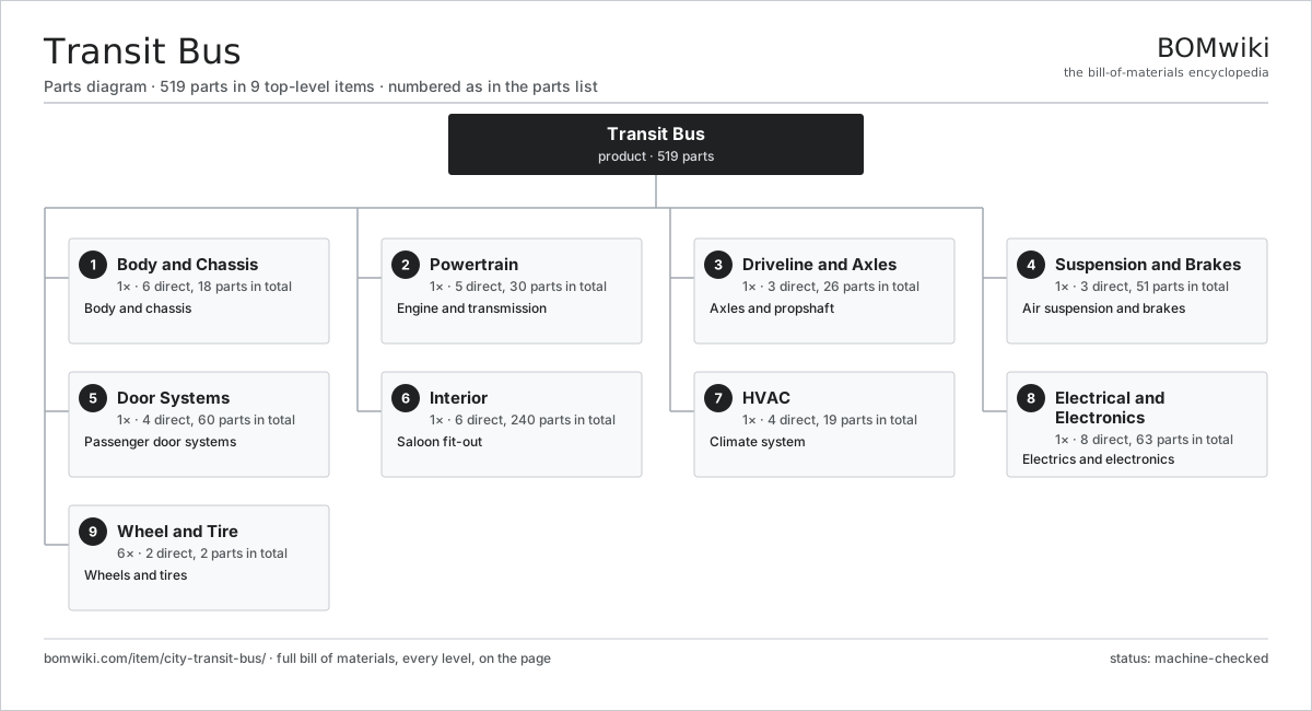
| # | Part | Qty | What it does |
|---|---|---|---|
| 1 | Body and Chassis 6 parts | 1× | Body and chassis |
| 2 | Powertrain 5 parts | 1× | Engine and transmission |
| 3 | Driveline and Axles 3 parts | 1× | Axles and propshaft |
| 4 | Suspension and Brakes 3 parts | 1× | Air suspension and brakes |
| 5 | Door Systems 4 parts | 1× | Passenger door systems |
| 6 | Interior 6 parts | 1× | Saloon fit-out |
| 7 | HVAC 4 parts | 1× | Climate system |
| 8 | Electrical and Electronics 8 parts | 1× | Electrics and electronics |
| 9 | Wheel and Tire 2 parts | 6× | Wheels and tires |
3D model
No 3D model yet. Have a CAD file of this? Add a 3D model. STL renders right on this page; STEP, FreeCAD, and OpenSCAD sources are welcome too (openly licensed, like all 3D models on BOMwiki).
Build & assembly graph
expand / collapse · shared sub-assemblies converge · links to related products · est. labourTap an assembly to expand/collapse · tap a part to open it · use “Open page” for any node · drag to pan, scroll to zoom.
Bill of materials for Transit Bus
9 top-level lines · 135 rows shown · 519 parts total · indented to 3 levels| # | Item / sub-assembly | Part no. | Qty/assy | Ext. qty | Parts | Type |
|---|---|---|---|---|---|---|
| 1 | Body and Chassis 6 parts | city-transit-bus-structure | 1× | 1 | 18 | assembly |
| 1.1 | Body Skeleton | city-transit-bus-skeleton | 1× | 1 | · | part |
| 1.2 | Low-Floor Underframe 3 parts | city-transit-bus-underframe | 1× | 1 | 6 | assembly |
| 1.2.1 | Floor Panel | city-transit-bus-floor-panel | 1× | 1 | · | part |
| 1.2.2 | Wheel Arch Box | city-transit-bus-wheel-arch | 4× | 4 | · | part |
| 1.2.3 | Sheet Metal Panel | sheet-panel | 1× | 1 | · | part |
| 1.3 | Body Panels 4 parts | city-transit-bus-body-panels | 1× | 1 | 8 | assembly |
| 1.3.1 | Side Panel | city-transit-bus-side-panel | 4× | 4 | · | part |
| 1.3.2 | Front Mask | city-transit-bus-front-mask | 1× | 1 | · | part |
| 1.3.3 | Rear Mask | city-transit-bus-rear-mask | 1× | 1 | · | part |
| 1.3.4 | Bumper | city-transit-bus-bumper | 2× | 2 | · | part |
| 1.4 | Roof Shell | city-transit-bus-roof | 1× | 1 | · | part |
| 1.5 | Bonded Glazing | city-transit-bus-glazing | 1× | 1 | · | part |
| 1.6 | Fastener Set | fastener-set | 1× | 1 | · | part |
| 2 | Powertrain 5 parts | city-transit-bus-powertrain | 1× | 1 | 30 | assembly |
| 2.1 | Engine | city-transit-bus-engine | 1× | 1 | · | part |
| 2.2 | Automatic Transmission 5 parts | city-transit-bus-transmission | 1× | 1 | 19 | assembly |
| 2.2.1 | Gearbox Housing | gearbox-housing | 1× | 1 | · | part |
| 2.2.2 | Helical Gear Pair | gear-pair | 5× | 5 | · | part |
| 2.2.3 | Ball Bearing | ball-bearing | 8× | 8 | · | part |
| 2.2.4 | Oil Seal | oil-seal | 4× | 4 | · | part |
| 2.2.5 | Hydraulic Retarder | city-transit-bus-retarder | 1× | 1 | · | part |
| 2.3 | Cooling Pack 4 parts | city-transit-bus-cooling-pack | 1× | 1 | 4 | assembly |
| 2.3.1 | Radiator | radiator | 1× | 1 | · | part |
| 2.3.2 | Coolant Pump | coolant-pump | 1× | 1 | · | part |
| 2.3.3 | Cooling Fan | city-transit-bus-cooling-fan | 1× | 1 | · | part |
| 2.3.4 | Charge-Air Cooler | city-transit-bus-charge-air-cooler | 1× | 1 | · | part |
| 2.4 | Fuel System 3 parts | city-transit-bus-fuel-system | 1× | 1 | 3 | assembly |
| 2.4.1 | Fuel Storage | city-transit-bus-fuel-tank | 1× | 1 | · | part |
| 2.4.2 | Fuel Pump | city-transit-bus-fuel-pump | 1× | 1 | · | part |
| 2.4.3 | Fuel Filter | city-transit-bus-fuel-filter | 1× | 1 | · | part |
| 2.5 | Exhaust Aftertreatment 3 parts | city-transit-bus-exhaust | 1× | 1 | 3 | assembly |
| 2.5.1 | Diesel Particulate Filter | city-transit-bus-dpf | 1× | 1 | · | part |
| 2.5.2 | SCR Catalyst | city-transit-bus-scr | 1× | 1 | · | part |
| 2.5.3 | Silencer | city-transit-bus-silencer | 1× | 1 | · | part |
| 3 | Driveline and Axles 3 parts | city-transit-bus-driveline | 1× | 1 | 26 | assembly |
| 3.1 | Front Axle 4 parts | city-transit-bus-front-axle | 1× | 1 | 10 | assembly |
| 3.1.1 | Steering Knuckle | city-transit-bus-steering-knuckle | 2× | 2 | · | part |
| 3.1.2 | Wheel Hub | city-transit-bus-hub | 2× | 2 | · | part |
| 3.1.3 | Ball Bearing | ball-bearing | 4× | 4 | · | part |
| 3.1.4 | Oil Seal | oil-seal | 2× | 2 | · | part |
| 3.2 | Rear Portal Axle 5 parts | city-transit-bus-portal-axle | 1× | 1 | 15 | assembly |
| 3.2.1 | Differential | city-transit-bus-differential | 1× | 1 | · | part |
| 3.2.2 | Portal Gearset | city-transit-bus-portal-gearset | 2× | 2 | · | part |
| 3.2.3 | Helical Gear Pair | gear-pair | 2× | 2 | · | part |
| 3.2.4 | Ball Bearing | ball-bearing | 6× | 6 | · | part |
| 3.2.5 | Oil Seal | oil-seal | 4× | 4 | · | part |
| 3.3 | Propshaft | city-transit-bus-propshaft | 1× | 1 | · | part |
| 4 | Suspension and Brakes 3 parts | city-transit-bus-suspension-brakes | 1× | 1 | 51 | assembly |
| 4.1 | Air Suspension 4 parts | city-transit-bus-air-suspension | 1× | 1 | 21 | assembly |
| 4.1.1 | Air Spring | city-transit-bus-air-bellow | 6× | 6 | · | part |
| 4.1.2 | Shock Absorber | city-transit-bus-shock-absorber | 6× | 6 | · | part |
| 4.1.3 | Levelling Valve | city-transit-bus-levelling-valve | 3× | 3 | · | part |
| 4.1.4 | ECAS Controller 4 parts + deeper › | city-transit-bus-suspension-ecu | 1× | 1 | 6 | assembly |
| 4.2 | Brake System 4 parts | city-transit-bus-brake-system | 1× | 1 | 24 | assembly |
| 4.2.1 | Disc Brake | city-transit-bus-disc-brake | 6× | 6 | · | part |
| 4.2.2 | Brake Chamber | city-transit-bus-brake-chamber | 6× | 6 | · | part |
| 4.2.3 | ABS/EBS Controller 4 parts + deeper › | city-transit-bus-abs-ecu | 1× | 1 | 8 | assembly |
| 4.2.4 | Pressure Sensor | pressure-sensor | 4× | 4 | · | part |
| 4.3 | Air Supply 3 parts | city-transit-bus-air-supply | 1× | 1 | 6 | assembly |
| 4.3.1 | Air Compressor | city-transit-bus-air-compressor | 1× | 1 | · | part |
| 4.3.2 | Air Dryer | city-transit-bus-air-dryer | 1× | 1 | · | part |
| 4.3.3 | Air Reservoir | city-transit-bus-air-tank | 4× | 4 | · | part |
| 5 | Door Systems 4 parts | city-transit-bus-doors | 1× | 1 | 60 | assembly |
| 5.1 | Front Door | city-transit-bus-front-door | 1× | 1 | · | part |
| 5.2 | Centre Door | city-transit-bus-centre-door | 1× | 1 | · | part |
| 5.3 | Door Drive 4 parts | city-transit-bus-door-drive | 2× | 2 | 28 | assembly |
| 5.3.1 | Servo Motor 4 parts + deeper › | servo-motor | 1× | 2 | 24 | assembly |
| 5.3.2 | Helical Gear Pair | gear-pair | 1× | 2 | · | part |
| 5.3.3 | Door Edge Sensor | city-transit-bus-door-sensor | 1× | 2 | · | part |
| 5.3.4 | Relay | relay | 2× | 4 | · | part |
| 5.4 | Passenger Counter | city-transit-bus-passenger-counter | 2× | 2 | · | part |
| 6 | Interior 6 parts | city-transit-bus-interior | 1× | 1 | 240 | assembly |
| 6.1 | Seat Assembly 5 parts | seat-assembly | 30× | 30 | 7 | assembly |
| 6.1.1 | Seat Frame | seat-frame | 1× | 30 | · | part |
| 6.1.2 | Seat Foam | seat-foam | 2× | 60 | · | part |
| 6.1.3 | Seat Cover | seat-cover | 1× | 30 | · | part |
| 6.1.4 | Seat Motor | seat-motor | 2× | 60 | · | part |
| 6.1.5 | Seat Heater Mat | seat-heater | 1× | 30 | · | part |
| 6.2 | Grab Rail System | city-transit-bus-grab-rail | 1× | 1 | · | part |
| 6.3 | Floor Covering | city-transit-bus-floor-covering | 1× | 1 | · | part |
| 6.4 | Driver Area 3 parts | city-transit-bus-driver-area | 1× | 1 | 11 | assembly |
| 6.4.1 | Seat Assembly 5 parts + deeper › | seat-assembly | 1× | 1 | 7 | assembly |
| 6.4.2 | Instrument Cluster 3 parts + deeper › | city-transit-bus-instrument-cluster | 1× | 1 | 3 | assembly |
| 6.4.3 | Driver Protection Screen | city-transit-bus-cab-screen | 1× | 1 | · | part |
| 6.5 | Passenger Information System 4 parts | city-transit-bus-pis | 1× | 1 | 16 | assembly |
| 6.5.1 | Destination Sign | city-transit-bus-destination-sign | 2× | 2 | · | part |
| 6.5.2 | Interior Display | city-transit-bus-interior-display | 2× | 2 | · | part |
| 6.5.3 | LCD Panel | lcd-panel | 2× | 2 | · | part |
| 6.5.4 | PIS Controller 4 parts + deeper › | city-transit-bus-pis-controller | 1× | 1 | 10 | assembly |
| 6.6 | Stop Request System | city-transit-bus-stop-request | 1× | 1 | · | part |
| 7 | HVAC 4 parts | city-transit-bus-hvac | 1× | 1 | 19 | assembly |
| 7.1 | Rooftop AC Pack 4 parts | city-transit-bus-roof-ac | 1× | 1 | 5 | assembly |
| 7.1.1 | AC Compressor | city-transit-bus-ac-compressor | 1× | 1 | · | part |
| 7.1.2 | Condenser | city-transit-bus-condenser | 1× | 1 | · | part |
| 7.1.3 | Evaporator | city-transit-bus-evaporator | 1× | 1 | · | part |
| 7.1.4 | Blower | city-transit-bus-blower | 2× | 2 | · | part |
| 7.2 | Saloon Heater 3 parts | city-transit-bus-saloon-heater | 2× | 2 | 3 | assembly |
| 7.2.1 | Heating Element | heating-element | 1× | 2 | · | part |
| 7.2.2 | Heater Matrix | city-transit-bus-heater-matrix | 1× | 2 | · | part |
| 7.2.3 | Blower | city-transit-bus-blower | 1× | 2 | · | part |
| 7.3 | Driver Climate Unit | city-transit-bus-driver-hvac | 1× | 1 | · | part |
| 7.4 | HVAC Controller 4 parts | city-transit-bus-hvac-controller | 1× | 1 | 7 | assembly |
| 7.4.1 | Bare PCB | pcb-bare | 1× | 1 | · | part |
| 7.4.2 | Microcontroller | mcu | 1× | 1 | · | part |
| 7.4.3 | Relay | relay | 4× | 4 | · | part |
| 7.4.4 | SMD Passive (R/C/L) | smd-passives | 1× | 1 | · | part |
| 8 | Electrical and Electronics 8 parts | city-transit-bus-electrical | 1× | 1 | 63 | assembly |
| 8.1 | Body Controller 5 parts | city-transit-bus-body-controller | 1× | 1 | 20 | assembly |
| 8.1.1 | Bare PCB | pcb-bare | 1× | 1 | · | part |
| 8.1.2 | Microcontroller | mcu | 2× | 2 | · | part |
| 8.1.3 | Relay | relay | 8× | 8 | · | part |
| 8.1.4 | SMD Passive (R/C/L) | smd-passives | 1× | 1 | · | part |
| 8.1.5 | Connector | connector | 8× | 8 | · | part |
| 8.2 | Vehicle Wiring 2 parts | city-transit-bus-wiring | 1× | 1 | 13 | assembly |
| 8.2.1 | Wire Bundle | wire-bundle | 1× | 1 | · | part |
| 8.2.2 | Connector | connector | 12× | 12 | · | part |
| 8.3 | 12 V Battery | lv-battery | 2× | 2 | · | part |
| 8.4 | Alternator | city-transit-bus-alternator | 1× | 1 | · | part |
| 8.5 | Lighting 3 parts | city-transit-bus-lighting | 1× | 1 | 12 | assembly |
| 8.5.1 | Interior Light | city-transit-bus-interior-light | 8× | 8 | · | part |
| 8.5.2 | Headlamp | city-transit-bus-headlamp | 2× | 2 | · | part |
| 8.5.3 | Tail Lamp | city-transit-bus-tail-lamp | 2× | 2 | · | part |
| 8.6 | CCTV System 2 parts | city-transit-bus-cctv | 1× | 1 | 9 | assembly |
| 8.6.1 | Camera | city-transit-bus-camera | 6× | 6 | · | part |
| 8.6.2 | Video Recorder 3 parts + deeper › | city-transit-bus-dvr | 1× | 1 | 3 | assembly |
| 8.7 | Fare Validator | city-transit-bus-fare-validator | 1× | 1 | · | part |
| 8.8 | Telematics Unit 4 parts | city-transit-bus-telematics | 1× | 1 | 5 | assembly |
| 8.8.1 | Bare PCB | pcb-bare | 1× | 1 | · | part |
| 8.8.2 | Microcontroller | mcu | 2× | 2 | · | part |
| 8.8.3 | GNSS Receiver | city-transit-bus-gnss | 1× | 1 | · | part |
| 8.8.4 | Cellular Modem | city-transit-bus-modem | 1× | 1 | · | part |
| 9 | Wheel and Tire 2 parts | city-transit-bus-wheels | 6× | 6 | 2 | assembly |
| 9.1 | Wheel Rim | city-transit-bus-wheel-rim | 1× | 6 | · | part |
| 9.2 | Tire | city-transit-bus-tire | 1× | 6 | · | part |
Related products
same domain, ranked by shared parts Commuter EMU
14,010 parts · shares 27 with this page
Commuter EMU
14,010 parts · shares 27 with this page
 Passenger Locomotive
10,641 parts · shares 26 with this page
Passenger Locomotive
10,641 parts · shares 26 with this page
 Diesel Multiple Unit
12,609 parts · shares 26 with this page
Diesel Multiple Unit
12,609 parts · shares 26 with this page
 Coach Bus
999 parts · shares 25 with this page
Coach Bus
999 parts · shares 25 with this page
 Diesel Shunter
4,407 parts · shares 24 with this page
Diesel Shunter
4,407 parts · shares 24 with this page
 Track Laying Machine
371 parts · shares 23 with this page
Track Laying Machine
371 parts · shares 23 with this page
Sourcing: possible vendors
Browse the supplier directory → Prices, MOQ, and lead times are algorithmic estimates, not quotes, and not claims about these companies. Company mappings are curated by keyword; est. price band $500k–$60M. How estimates work| Vendor | HQ | Specialty | MOQ | Lead time |
|---|---|---|---|---|
|
🇨🇳CRRC
crrcgc.cc ↗
|
Beijing, CN | Rolling stock & rail systems | made to order | 40–72 wks |
|
🇫🇷Alstom
alstom.com ↗
|
Saint-Ouen, FR | Rail rolling stock | made to order | 40–72 wks |
| mobility.siemens.com ↗ | Munich, DE | Rail systems | made to order | 40–72 wks |
| stadlerrail.com ↗ | Bussnang, CH | Rail rolling stock | made to order | 40–72 wks |
|
🇺🇸Wabtec
wabteccorp.com ↗
|
Pittsburgh, US | Rail equipment | made to order | 40–72 wks |
1,098-word article