Traction Transformer
ProductOverview
A Traction Transformer is the first power-conversion stage on an electric locomotive or multiple unit. It sits under the carbody, draws single-phase power from the overhead catenary through the pantograph, and steps the high catenary voltage down to the few-kilovolt level that the on-board traction converters need. From there, four-quadrant line converters rectify the single-phase supply to a DC link, and inverters drive the traction motors. The transformer is single-phase because the railway contact system is single-phase, which sets it apart from the three-phase grid units.
Two supply standards dominate. Much of Europe outside the German-speaking countries, plus most high-speed lines, uses 25 kV at 50 Hz; Germany, Austria, Switzerland, Norway and Sweden use 15 kV at 16.7 Hz. A transformer for the low-frequency system needs a larger core for the same power because core size scales inversely with frequency. The unit must also survive the railway environment: continuous vibration, shock, wide temperature swings, and a strict size and weight limit because it hangs under the vehicle.
Magnetic core
The Magnetic Core is a single-phase grain-oriented silicon-steel core with two wound limbs and two yokes. Compared with a substation transformer, the clamping frames are reinforced and the stack is held more tightly, because the core is exposed to track-induced shock and must not loosen or buzz over a 30-year life. Anti-vibration pads under the core feet, together with the underframe suspension, keep that vibration from cracking insulation or fatiguing leads.
Windings
The winding assembly has one catenary primary winding and several secondaries. Modern drives use one traction secondary per line converter, typically two to four, so the converters can be paralleled and the harmonic content on the line reduced by phase-shifting. A separate auxiliary winding supplies HVAC, lighting and battery charging, and a filter winding couples to a resonant circuit that damps the harmonics the converters inject back toward the catenary.
A defining feature is the deliberately high leakage impedance, often around 30 percent per secondary. The transformer is used as the line inductance of the four-quadrant converter, so its leakage reactance is a design parameter of the drive rather than something to be minimised. The traction secondaries carry pulsed converter current, so they are wound from transposed conductor to hold eddy losses down, and the primary is graded with static rings against the steep surges that arrive from the catenary when the pantograph bounces or a neutral section is crossed.
Insulating fluid
The insulation system usually uses synthetic ester fluid rather than mineral oil. Esters have a much higher fire point, around 300 C, which matters for a fluid-filled unit carried inside a passenger vehicle, and they are biodegradable, which matters for a tank that travels through tunnels, stations and the open environment. The ester impregnates the kraft paper and fills the gaps set by barrier cylinders and pressboard spacers, with angle rings grading the field at edges.
Cooling and packaging
Power density is high and space is scarce, so the cooling system is forced. The compact underframe tank is fitted with pumps that drive ester through the windings and out to an oil cooler. The cooler rejects heat either to ambient air through fans (OFAF) or to a water-glycol loop driven by the coolant pump up to a roof radiator (OFWF). The whole assembly is shaped to fit within the vehicle loading gauge, which is why traction transformers are long, low and flat rather than the tall cylindrical shape of a substation unit.
Connections, preservation and protection
The primary connects through a lightweight roof bushing to the pantograph circuit, and the secondaries connect through sealed terminals to the converters. Because the vehicle is in constant motion and can tilt, oil preservation uses a sealed expansion bladder rather than an open conservator, so air and moisture never enter and the fluid is not disturbed by acceleration.
Protection mirrors a grid transformer but is tied into the train control system. A Buchholz relay, sudden-pressure relay and pressure-relief device guard against internal faults, while the winding and fluid temperature sensors feed the drive controller. A monitoring board gathers the signals and reports over the train bus so the driver and depot see the transformer's condition in real time. Everything terminates in the sealed terminal box.
Mounting and standards
The transformer is suspended on a mounting frame through elastomeric isolators, with crash shear pins to limit longitudinal travel under heavy braking and earthing brushes bonding it to the carbody. Traction transformers are designed and tested to IEC 60310 (railway transformers), EN 50329, and the railway shock-and-vibration standard IEC 61373, which together fix the electrical ratings, the fire behaviour of the fluid, and the mechanical robustness the on-board unit must show before it is accepted onto a vehicle.
Traction Transformer parts and their functions
9 top-level parts · 4,404 parts in total · full bill of materials below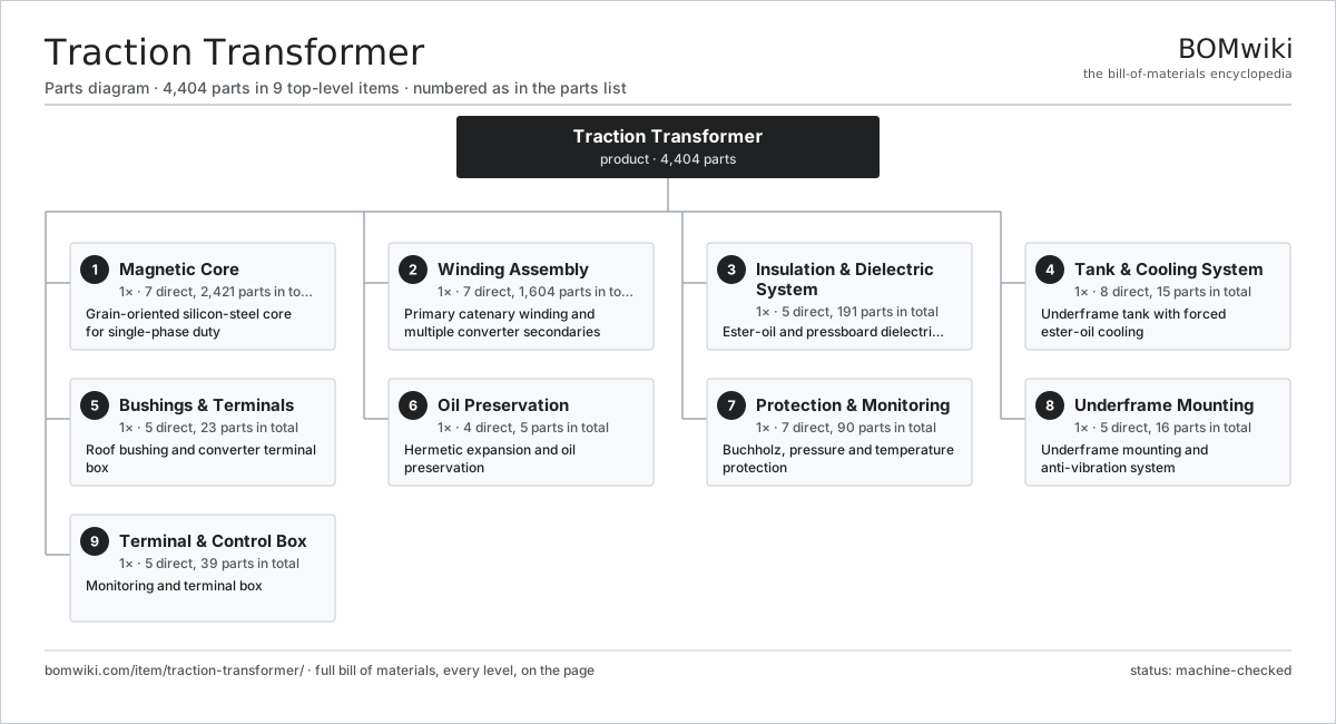
| # | Part | Qty | What it does |
|---|---|---|---|
| 1 | Magnetic Core 7 parts | 1× | Grain-oriented silicon-steel core for single-phase duty |
| 2 | Winding Assembly 7 parts | 1× | Primary catenary winding and multiple converter secondaries |
| 3 | Insulation & Dielectric System 5 parts | 1× | Ester-oil and pressboard dielectric system |
| 4 | Tank & Cooling System 8 parts | 1× | Underframe tank with forced ester-oil cooling |
| 5 | Bushings & Terminals 5 parts | 1× | Roof bushing and converter terminal box |
| 6 | Oil Preservation 4 parts | 1× | Hermetic expansion and oil preservation |
| 7 | Protection & Monitoring 7 parts | 1× | Buchholz, pressure and temperature protection |
| 8 | Underframe Mounting 5 parts | 1× | Underframe mounting and anti-vibration system |
| 9 | Terminal & Control Box 5 parts | 1× | Monitoring and terminal box |
3D model
No 3D model yet. Have a CAD file of this? Add a 3D model. STL renders right on this page; STEP, FreeCAD, and OpenSCAD sources are welcome too (openly licensed, like all 3D models on BOMwiki).
Build & assembly graph
expand / collapse · shared sub-assemblies converge · links to related products · est. labourTap an assembly to expand/collapse · tap a part to open it · use “Open page” for any node · drag to pan, scroll to zoom.
Bill of materials for Traction Transformer
9 top-level lines · 73 rows shown · 4,404 parts total · indented to 3 levels| # | Item / sub-assembly | Part no. | Qty/assy | Ext. qty | Parts | Type |
|---|---|---|---|---|---|---|
| 1 | Magnetic Core 7 parts | traction-transformer-core | 1× | 1 | 2,421 | assembly |
| 1.1 | GO Silicon-Steel Lamination | traction-transformer-core-lamination | 2400× | 2,400 | · | part |
| 1.2 | Core Limb | traction-transformer-core-limb | 2× | 2 | · | part |
| 1.3 | Core Yoke | traction-transformer-core-yoke | 2× | 2 | · | part |
| 1.4 | Core Clamping Frame | traction-transformer-clamping-frame | 2× | 2 | · | part |
| 1.5 | Core Tie Rod | traction-transformer-core-tie-rod | 6× | 6 | · | part |
| 1.6 | Core Earthing Strap | traction-transformer-core-ground-strap | 1× | 1 | · | part |
| 1.7 | Anti-Vibration Pad | traction-transformer-vibration-pad | 8× | 8 | · | part |
| 2 | Winding Assembly 7 parts | traction-transformer-windings | 1× | 1 | 1,604 | assembly |
| 2.1 | Catenary Primary Winding 4 parts | traction-transformer-primary-winding | 1× | 1 | 204 | assembly |
| 2.1.1 | Paper-Covered Copper Conductor | traction-transformer-copper-conductor | 1× | 1 | · | part |
| 2.1.2 | Kraft Paper Insulation | traction-transformer-paper-insulation | 1× | 1 | · | part |
| 2.1.3 | Electrostatic Static Ring | traction-transformer-static-ring | 2× | 2 | · | part |
| 2.1.4 | Pressboard Spacer | traction-transformer-pressboard-spacer | 200× | 200 | · | part |
| 2.2 | Traction Secondary Winding 3 parts | traction-transformer-traction-secondary | 4× | 4 | 122 | assembly |
| 2.2.1 | Transposed Copper Conductor | traction-transformer-ctc-conductor | 1× | 4 | · | part |
| 2.2.2 | Kraft Paper Insulation | traction-transformer-paper-insulation | 1× | 4 | · | part |
| 2.2.3 | Pressboard Spacer | traction-transformer-pressboard-spacer | 120× | 480 | · | part |
| 2.3 | Auxiliary Winding | traction-transformer-auxiliary-secondary | 1× | 1 | · | part |
| 2.4 | Harmonic Filter Winding | traction-transformer-filter-winding | 1× | 1 | · | part |
| 2.5 | Pressboard Spacer | traction-transformer-pressboard-spacer | 900× | 900 | · | part |
| 2.6 | Barrier Cylinder | traction-transformer-barrier-cylinder | 6× | 6 | · | part |
| 2.7 | Winding Clamping Ring | traction-transformer-clamping-ring | 4× | 4 | · | part |
| 3 | Insulation & Dielectric System 5 parts | traction-transformer-insulation | 1× | 1 | 191 | assembly |
| 3.1 | Synthetic-Ester Fluid | traction-transformer-ester-oil | 1× | 1 | · | part |
| 3.2 | Pressboard Angle Ring | traction-transformer-angle-ring | 40× | 40 | · | part |
| 3.3 | Lead Snout | traction-transformer-snout | 6× | 6 | · | part |
| 3.4 | Oil Duct Stick | traction-transformer-duct-stick | 140× | 140 | · | part |
| 3.5 | End Insulation Block | traction-transformer-end-block | 4× | 4 | · | part |
| 4 | Tank & Cooling System 8 parts | traction-transformer-tank-cooling | 1× | 1 | 15 | assembly |
| 4.1 | Underframe Tank | traction-transformer-main-tank | 1× | 1 | · | part |
| 4.2 | Oil Cooler | traction-transformer-oil-cooler | 1× | 1 | · | part |
| 4.3 | Oil Circulation Pump | traction-transformer-oil-pump | 2× | 2 | · | part |
| 4.4 | Cooler Fan | traction-transformer-cooling-fan | 4× | 4 | · | part |
| 4.5 | Water-Glycol Pump | traction-transformer-coolant-pump | 1× | 1 | · | part |
| 4.6 | Tank Valve | traction-transformer-tank-valve | 4× | 4 | · | part |
| 4.7 | Fastener Set | fastener-set | 1× | 1 | · | part |
| 4.8 | O-Ring Set | oring-set | 1× | 1 | · | part |
| 5 | Bushings & Terminals 5 parts | traction-transformer-bushings | 1× | 1 | 23 | assembly |
| 5.1 | Primary Roof Bushing | traction-transformer-primary-bushing | 1× | 1 | · | part |
| 5.2 | Secondary Terminal | traction-transformer-secondary-terminal | 4× | 4 | · | part |
| 5.3 | Auxiliary Terminal | traction-transformer-auxiliary-terminal | 1× | 1 | · | part |
| 5.4 | Terminal Current Transformer | traction-transformer-bushing-ct | 5× | 5 | · | part |
| 5.5 | Cable Lug | cable-lug | 12× | 12 | · | part |
| 6 | Oil Preservation 4 parts | traction-transformer-preservation | 1× | 1 | 5 | assembly |
| 6.1 | Expansion Bladder | traction-transformer-expansion-bladder | 1× | 1 | · | part |
| 6.2 | Sealed Dehydrator | traction-transformer-breather | 1× | 1 | · | part |
| 6.3 | Fluid Level Sensor | traction-transformer-oil-level-sensor | 1× | 1 | · | part |
| 6.4 | Fill / Vent Valve | traction-transformer-fill-valve | 2× | 2 | · | part |
| 7 | Protection & Monitoring 7 parts | traction-transformer-protection | 1× | 1 | 90 | assembly |
| 7.1 | Buchholz Relay | traction-transformer-buchholz-relay | 1× | 1 | · | part |
| 7.2 | Pressure Relief Device | traction-transformer-pressure-relief | 1× | 1 | · | part |
| 7.3 | Sudden-Pressure Relay | traction-transformer-sudden-pressure-relay | 1× | 1 | · | part |
| 7.4 | Winding Temperature Sensor | traction-transformer-wti | 1× | 1 | · | part |
| 7.5 | Fluid Temperature Sensor | traction-transformer-oti | 1× | 1 | · | part |
| 7.6 | Pressure Sensor | pressure-sensor | 2× | 2 | · | part |
| 7.7 | Monitoring Board 4 parts | traction-transformer-monitor-board | 1× | 1 | 83 | assembly |
| 7.7.1 | Bare PCB | pcb-bare | 1× | 1 | · | part |
| 7.7.2 | Microcontroller | mcu | 1× | 1 | · | part |
| 7.7.3 | CAN Transceiver | can-transceiver | 1× | 1 | · | part |
| 7.7.4 | SMD Passive (R/C/L) | smd-passives | 80× | 80 | · | part |
| 8 | Underframe Mounting 5 parts | traction-transformer-mounting | 1× | 1 | 16 | assembly |
| 8.1 | Suspension Mount Frame | traction-transformer-mount-frame | 1× | 1 | · | part |
| 8.2 | Anti-Vibration Isolator | traction-transformer-isolator | 8× | 8 | · | part |
| 8.3 | Crash Shear Pin | traction-transformer-shear-pin | 4× | 4 | · | part |
| 8.4 | Earthing Brush | traction-transformer-earth-brush | 2× | 2 | · | part |
| 8.5 | Fastener Set | fastener-set | 1× | 1 | · | part |
| 9 | Terminal & Control Box 5 parts | traction-transformer-control-box | 1× | 1 | 39 | assembly |
| 9.1 | Sheet Metal Panel | sheet-panel | 4× | 4 | · | part |
| 9.2 | Terminal Block | traction-transformer-terminal-block | 24× | 24 | · | part |
| 9.3 | Wire Bundle | wire-bundle | 1× | 1 | · | part |
| 9.4 | Connector | connector | 6× | 6 | · | part |
| 9.5 | Relay | relay | 4× | 4 | · | part |
Related products
same domain, ranked by shared parts Airport Apron Bus
759 parts · shares 4 with this page
Airport Apron Bus
759 parts · shares 4 with this page
 Commuter EMU
14,010 parts · shares 4 with this page
Commuter EMU
14,010 parts · shares 4 with this page
 Diesel Multiple Unit
12,609 parts · shares 4 with this page
Diesel Multiple Unit
12,609 parts · shares 4 with this page
 Freight Locomotive
1,597 parts · shares 4 with this page
Freight Locomotive
1,597 parts · shares 4 with this page
 Passenger Locomotive
10,641 parts · shares 4 with this page
Passenger Locomotive
10,641 parts · shares 4 with this page
 City Bus
40,967 parts · shares 3 with this page
City Bus
40,967 parts · shares 3 with this page
Sourcing: possible vendors
Browse the supplier directory → Prices, MOQ, and lead times are algorithmic estimates, not quotes, and not claims about these companies. Company mappings are curated by keyword; est. price band $500k–$60M. How estimates work| Vendor | HQ | Specialty | MOQ | Lead time |
|---|---|---|---|---|
|
🇨🇳CRRC
crrcgc.cc ↗
|
Beijing, CN | Rolling stock & rail systems | made to order | 40–72 wks |
|
🇫🇷Alstom
alstom.com ↗
|
Saint-Ouen, FR | Rail rolling stock | made to order | 40–72 wks |
| mobility.siemens.com ↗ | Munich, DE | Rail systems | made to order | 40–72 wks |
| stadlerrail.com ↗ | Bussnang, CH | Rail rolling stock | made to order | 40–72 wks |
|
🇺🇸Wabtec
wabteccorp.com ↗
|
Pittsburgh, US | Rail equipment | made to order | 40–72 wks |
976-word article