Freight Locomotive
ProductOverview
A freight locomotive is a self-contained traction unit that converts diesel fuel into pulling force at the rail. Almost every road freight locomotive built since the 1950s uses diesel-electric transmission: a diesel engine spins an alternator, the alternator feeds electric traction motors, and the motors drive the wheels through gears. There is no mechanical clutch or gearbox between engine and wheels, which is what lets one engine speed serve everything from a standing start with a 12,000-ton train to 70 mph on level track. The unit described here is built around the Carbody and Underframe underframe, riding on two Powered Bogie three-axle bogies, powered by the Diesel Prime Mover driving the Main Traction Alternator, with current routed through the Traction Power Converter to six Traction Motor units. Supporting systems include the Cooling Group, the Air Brake System, the Locomotive Control System, the Fuel System, and the Operator Cab.
Carbody, frame, and bogies
The structural backbone is the Main Underframe, a heavy welded steel frame with a center sill running the full length. It carries the draft and buff forces of the train: a loaded freight locomotive may pull against a coupler load of several hundred thousand pounds, and that load passes through the Coupler and Draft Gear draft gear into the frame, not the body shell. The Hood Section sections over the engine room are non-structural sheet steel that only weatherproof and enclose the machinery.
Each Powered Bogie carries three Motored Wheelset assemblies. A wheelset is an Axle pressed with two Monobloc Wheel monobloc wheels, running on Axle-Box Roller Bearing roller bearings, and carrying the Bull Gear that the motor drives. The Bogie Frame supports the motors and the Coil Spring primary suspension, while the Secondary Suspension with its Bogie Bolster transfers body weight and tractive effort through the Side Bearer bearers. Braking on the bogie is by Tread Brake Unit units that press a Composition Brake Shoe against the wheel tread, kept adjusted by the Slack Adjuster. The Sandbox and Sander sanders drop sand on the rail ahead of the wheels to raise adhesion when starting a heavy train or climbing a wet grade.
Prime mover and electrical transmission
The Diesel Prime Mover is a medium-speed engine running around 900 to 1050 rpm, with 12 to 16 cylinders arranged in a V. Its Engine Block carries the Crankshaft, and each cylinder is a removable Cylinder Power Assembly holding a Cylinder Liner, a Piston and Rings, a Connecting Rod, a Cylinder Head, and a Unit Fuel Injector. Designing the cylinder as a power pack means a worn unit can be changed in the field without splitting the whole engine. The Turbocharger recovers exhaust energy to force charge air in, raising output by roughly half over a naturally aspirated engine. The Engine Governor sets fuel rack position for the throttle notch the driver selects, and the Lube Oil System keeps the bearings fed.
The crankshaft drives the Main Traction Alternator directly. Its three- phase output goes to the Main Rectifier, which converts it to a DC link, and the Exciter and Field Control regulates the field to control how much power the alternator delivers. On modern AC-traction units the Traction Power Converter then uses Traction Inverter inverters built from IGBT Power Module modules to make variable-frequency power for the Traction Motor units. Each motor drives its wheelset through a Motor Pinion meshing with the bull gear.
Braking, cooling, and control
A freight locomotive brakes two ways. The Air Brake System system uses the Air Compressor to charge the Main Reservoir tanks, and the Automatic Brake Valve meters air into the train brake pipe so every car in the consist brakes together. For continuous control on long downgrades the Traction Power Converter runs the traction motors as generators and dumps their output into the Dynamic Brake Grid, where Brake Resistor Element elements turn the train's kinetic energy into heat. That spares the friction brakes from overheating on a multi-mile descent.
The engine and converters reject a great deal of heat, handled by the Cooling Group: Radiator Core cores cooled by Radiator Fan fans, with Engine Water Pump pumps circulating coolant regulated by the Thermostatic Valve. Overseeing all of it is the Locomotive Control System, whose Traction Control Computer coordinates engine speed, alternator excitation, and inverter output, while the Wheelslip Control Unit compares axle speeds from the Wheel Speed Sensor pickups and trims tractive effort the instant a wheel begins to slip. The Operator Cab gives the crew a Control Desk with throttle and reverser, while the Fuel System feeds the engine from a large underslung Fuel Tank.
Variants and use
Freight locomotives are built in families that share the same engine and electrics but differ in gearing and weight. A unit geared for heavy drag service trades top speed for tractive effort, while an intermodal unit geared higher runs faster with lighter trains. Many railroads run several locomotives in multiple, controlled from one cab through trainline cables, so a single crew can command 15,000 or more horsepower for a heavy train. Distributed power places extra units mid-train or at the rear, radio-linked to the lead, which reduces coupler forces on long consists. Older units use DC traction motors with a simpler control scheme; newer ones use AC motors and inverters, which give better adhesion and need less maintenance because there are no commutator brushes to wear.
Freight Locomotive parts and their functions
12 top-level parts · 1,597 parts in total · full bill of materials below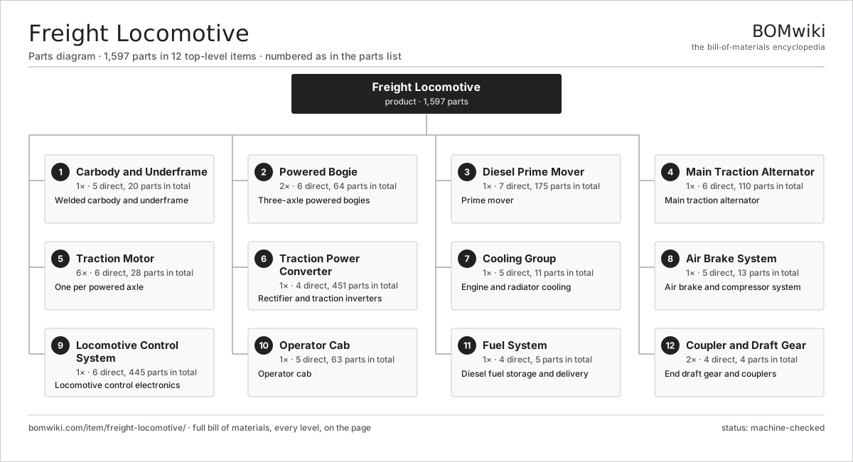
| # | Part | Qty | What it does |
|---|---|---|---|
| 1 | Carbody and Underframe 5 parts | 1× | Welded carbody and underframe |
| 2 | Powered Bogie 6 parts | 2× | Three-axle powered bogies |
| 3 | Diesel Prime Mover 7 parts | 1× | Prime mover |
| 4 | Main Traction Alternator 6 parts | 1× | Main traction alternator |
| 5 | Traction Motor 6 parts | 6× | One per powered axle |
| 6 | Traction Power Converter 4 parts | 1× | Rectifier and traction inverters |
| 7 | Cooling Group 5 parts | 1× | Engine and radiator cooling |
| 8 | Air Brake System 5 parts | 1× | Air brake and compressor system |
| 9 | Locomotive Control System 6 parts | 1× | Locomotive control electronics |
| 10 | Operator Cab 5 parts | 1× | Operator cab |
| 11 | Fuel System 4 parts | 1× | Diesel fuel storage and delivery |
| 12 | Coupler and Draft Gear 4 parts | 2× | End draft gear and couplers |
3D model
No 3D model yet. Have a CAD file of this? Add a 3D model. STL renders right on this page; STEP, FreeCAD, and OpenSCAD sources are welcome too (openly licensed, like all 3D models on BOMwiki).
Build & assembly graph
expand / collapse · shared sub-assemblies converge · links to related products · est. labourTap an assembly to expand/collapse · tap a part to open it · use “Open page” for any node · drag to pan, scroll to zoom.
Bill of materials for Freight Locomotive
12 top-level lines · 155 rows shown · 1,597 parts total · indented to 3 levels| # | Item / sub-assembly | Part no. | Qty/assy | Ext. qty | Parts | Type |
|---|---|---|---|---|---|---|
| 1 | Carbody and Underframe 5 parts | freight-locomotive-carbody | 1× | 1 | 20 | assembly |
| 1.1 | Main Underframe | freight-locomotive-underframe | 1× | 1 | · | part |
| 1.2 | Hood Section | freight-locomotive-hood | 2× | 2 | · | part |
| 1.3 | Fuel Tank Cradle | freight-locomotive-fuel-tank-cradle | 1× | 1 | · | part |
| 1.4 | Sheet Metal Panel | sheet-panel | 12× | 12 | · | part |
| 1.5 | Fastener Set | fastener-set | 4× | 4 | · | part |
| 2 | Powered Bogie 6 parts | freight-locomotive-bogie | 2× | 2 | 64 | assembly |
| 2.1 | Bogie Frame | freight-locomotive-bogie-frame | 1× | 2 | · | part |
| 2.2 | Motored Wheelset 4 parts | freight-locomotive-wheelset | 3× | 6 | 6 | assembly |
| 2.2.1 | Axle | freight-locomotive-axle | 1× | 6 | · | part |
| 2.2.2 | Monobloc Wheel | freight-locomotive-wheel | 2× | 12 | · | part |
| 2.2.3 | Axle-Box Roller Bearing | freight-locomotive-axle-bearing | 2× | 12 | · | part |
| 2.2.4 | Bull Gear | freight-locomotive-bull-gear | 1× | 6 | · | part |
| 2.3 | Coil Spring | coil-spring | 12× | 24 | · | part |
| 2.4 | Secondary Suspension 3 parts | freight-locomotive-secondary-suspension | 1× | 2 | 11 | assembly |
| 2.4.1 | Bogie Bolster | freight-locomotive-bolster | 1× | 2 | · | part |
| 2.4.2 | Coil Spring | coil-spring | 8× | 16 | · | part |
| 2.4.3 | Side Bearer | freight-locomotive-side-bearer | 2× | 4 | · | part |
| 2.5 | Tread Brake Unit 3 parts | freight-locomotive-tread-brake | 6× | 12 | 3 | assembly |
| 2.5.1 | Brake Cylinder | freight-locomotive-brake-cylinder | 1× | 12 | · | part |
| 2.5.2 | Composition Brake Shoe | freight-locomotive-brake-shoe | 1× | 12 | · | part |
| 2.5.3 | Slack Adjuster | freight-locomotive-slack-adjuster | 1× | 12 | · | part |
| 2.6 | Sandbox and Sander | freight-locomotive-sandbox | 4× | 8 | · | part |
| 3 | Diesel Prime Mover 7 parts | freight-locomotive-diesel-engine | 1× | 1 | 175 | assembly |
| 3.1 | Engine Block | freight-locomotive-engine-block | 1× | 1 | · | part |
| 3.2 | Crankshaft | freight-locomotive-crankshaft | 1× | 1 | · | part |
| 3.3 | Cylinder Power Assembly 6 parts | freight-locomotive-power-assembly | 16× | 16 | 6 | assembly |
| 3.3.1 | Cylinder Liner | freight-locomotive-cylinder-liner | 1× | 16 | · | part |
| 3.3.2 | Piston and Rings | freight-locomotive-piston | 1× | 16 | · | part |
| 3.3.3 | Connecting Rod | freight-locomotive-connecting-rod | 1× | 16 | · | part |
| 3.3.4 | Cylinder Head | freight-locomotive-cylinder-head | 1× | 16 | · | part |
| 3.3.5 | Unit Fuel Injector | freight-locomotive-fuel-injector | 1× | 16 | · | part |
| 3.3.6 | O-Ring Set | oring-set | 1× | 16 | · | part |
| 3.4 | Turbocharger 4 parts | freight-locomotive-turbocharger | 1× | 1 | 6 | assembly |
| 3.4.1 | Turbine Wheel | freight-locomotive-turbine-wheel | 1× | 1 | · | part |
| 3.4.2 | Compressor Wheel | freight-locomotive-compressor-wheel | 1× | 1 | · | part |
| 3.4.3 | Ball Bearing | ball-bearing | 2× | 2 | · | part |
| 3.4.4 | Oil Seal | oil-seal | 2× | 2 | · | part |
| 3.5 | Fuel Injection Manifold | freight-locomotive-fuel-injection | 1× | 1 | · | part |
| 3.6 | Lube Oil System 3 parts | freight-locomotive-lube-oil-system | 1× | 1 | 6 | assembly |
| 3.6.1 | Lube Oil Pump | freight-locomotive-oil-pump | 1× | 1 | · | part |
| 3.6.2 | Oil Filter | freight-locomotive-oil-filter | 4× | 4 | · | part |
| 3.6.3 | Oil Cooler | freight-locomotive-oil-cooler | 1× | 1 | · | part |
| 3.7 | Engine Governor 4 parts | freight-locomotive-governor | 1× | 1 | 64 | assembly |
| 3.7.1 | Bare PCB | pcb-bare | 1× | 1 | · | part |
| 3.7.2 | Microcontroller | mcu | 1× | 1 | · | part |
| 3.7.3 | Pressure Sensor | pressure-sensor | 2× | 2 | · | part |
| 3.7.4 | SMD Passive (R/C/L) | smd-passives | 60× | 60 | · | part |
| 4 | Main Traction Alternator 6 parts | freight-locomotive-alternator | 1× | 1 | 110 | assembly |
| 4.1 | Stator Assembly 3 parts | stator-assembly | 1× | 1 | 3 | assembly |
| 4.1.1 | Stator Core (laminations) | stator-core | 1× | 1 | · | part |
| 4.1.2 | Copper Winding | copper-winding | 1× | 1 | · | part |
| 4.1.3 | Slot Insulation | stator-insulation | 1× | 1 | · | part |
| 4.2 | Rotor Assembly 4 parts | rotor-assembly | 1× | 1 | 19 | assembly |
| 4.2.1 | Rotor Shaft | rotor-shaft | 1× | 1 | · | part |
| 4.2.2 | Rotor Core | rotor-core | 1× | 1 | · | part |
| 4.2.3 | Neodymium Magnet | neodymium-magnet | 16× | 16 | · | part |
| 4.2.4 | Ball Bearing | ball-bearing | 1× | 1 | · | part |
| 4.3 | Main Rectifier | freight-locomotive-rectifier | 1× | 1 | · | part |
| 4.4 | Exciter and Field Control 4 parts | freight-locomotive-exciter | 1× | 1 | 84 | assembly |
| 4.4.1 | Bare PCB | pcb-bare | 1× | 1 | · | part |
| 4.4.2 | Microcontroller | mcu | 1× | 1 | · | part |
| 4.4.3 | Current Sensor | current-sensor | 2× | 2 | · | part |
| 4.4.4 | SMD Passive (R/C/L) | smd-passives | 80× | 80 | · | part |
| 4.5 | Ball Bearing | ball-bearing | 2× | 2 | · | part |
| 4.6 | Alternator Housing | freight-locomotive-alternator-housing | 1× | 1 | · | part |
| 5 | Traction Motor 6 parts | freight-locomotive-traction-motor | 6× | 6 | 28 | assembly |
| 5.1 | Stator Assembly 3 parts | stator-assembly | 1× | 6 | 3 | assembly |
| 5.1.1 | Stator Core (laminations) | stator-core | 1× | 6 | · | part |
| 5.1.2 | Copper Winding | copper-winding | 1× | 6 | · | part |
| 5.1.3 | Slot Insulation | stator-insulation | 1× | 6 | · | part |
| 5.2 | Rotor Assembly 4 parts | rotor-assembly | 1× | 6 | 19 | assembly |
| 5.2.1 | Rotor Shaft | rotor-shaft | 1× | 6 | · | part |
| 5.2.2 | Rotor Core | rotor-core | 1× | 6 | · | part |
| 5.2.3 | Neodymium Magnet | neodymium-magnet | 16× | 96 | · | part |
| 5.2.4 | Ball Bearing | ball-bearing | 1× | 6 | · | part |
| 5.3 | Motor Pinion | freight-locomotive-motor-pinion | 1× | 6 | · | part |
| 5.4 | Ball Bearing | ball-bearing | 2× | 12 | · | part |
| 5.5 | Motor Suspension Bearing | freight-locomotive-motor-suspension-bearing | 2× | 12 | · | part |
| 5.6 | Wheel Speed Sensor | freight-locomotive-speed-sensor | 1× | 6 | · | part |
| 6 | Traction Power Converter 4 parts | freight-locomotive-power-converter | 1× | 1 | 451 | assembly |
| 6.1 | Traction Inverter 4 parts | freight-locomotive-traction-inverter | 2× | 2 | 220 | assembly |
| 6.1.1 | IGBT Power Module | freight-locomotive-igbt-module | 6× | 12 | · | part |
| 6.1.2 | Gate Driver Board 3 parts + deeper › | gate-driver-board | 1× | 2 | 87 | assembly |
| 6.1.3 | DC-Link Capacitor | dc-link-cap | 4× | 8 | · | part |
| 6.1.4 | Inverter Control Board 4 parts + deeper › | inverter-control-board | 1× | 2 | 123 | assembly |
| 6.2 | DC Link Capacitor Bank | freight-locomotive-dc-link | 1× | 1 | · | part |
| 6.3 | Dynamic Brake Grid 2 parts | freight-locomotive-dynamic-brake-grid | 1× | 1 | 9 | assembly |
| 6.3.1 | Brake Resistor Element | freight-locomotive-brake-resistor | 8× | 8 | · | part |
| 6.3.2 | Grid Blower Motor | freight-locomotive-grid-blower | 1× | 1 | · | part |
| 6.4 | Converter Cabinet | freight-locomotive-converter-cabinet | 1× | 1 | · | part |
| 7 | Cooling Group 5 parts | freight-locomotive-cooling-group | 1× | 1 | 11 | assembly |
| 7.1 | Radiator Core | freight-locomotive-radiator | 4× | 4 | · | part |
| 7.2 | Radiator Fan | freight-locomotive-radiator-fan | 2× | 2 | · | part |
| 7.3 | Engine Water Pump | freight-locomotive-water-pump | 2× | 2 | · | part |
| 7.4 | Expansion Tank | freight-locomotive-expansion-tank | 1× | 1 | · | part |
| 7.5 | Thermostatic Valve | freight-locomotive-thermostat | 2× | 2 | · | part |
| 8 | Air Brake System 5 parts | freight-locomotive-air-brake | 1× | 1 | 13 | assembly |
| 8.1 | Air Compressor 4 parts | freight-locomotive-air-compressor | 1× | 1 | 8 | assembly |
| 8.1.1 | Compressor Cylinder | freight-locomotive-compressor-cylinder | 3× | 3 | · | part |
| 8.1.2 | Compressor Crankshaft | freight-locomotive-compressor-crank | 1× | 1 | · | part |
| 8.1.3 | Ball Bearing | ball-bearing | 2× | 2 | · | part |
| 8.1.4 | O-Ring Set | oring-set | 2× | 2 | · | part |
| 8.2 | Main Reservoir | freight-locomotive-main-reservoir | 2× | 2 | · | part |
| 8.3 | Automatic Brake Valve | freight-locomotive-brake-valve | 1× | 1 | · | part |
| 8.4 | Distributor Valve | freight-locomotive-distributor-valve | 1× | 1 | · | part |
| 8.5 | Air Dryer | freight-locomotive-air-dryer | 1× | 1 | · | part |
| 9 | Locomotive Control System 6 parts | freight-locomotive-control-system | 1× | 1 | 445 | assembly |
| 9.1 | Traction Control Computer 5 parts | freight-locomotive-control-computer | 1× | 1 | 207 | assembly |
| 9.1.1 | Bare PCB | pcb-bare | 2× | 2 | · | part |
| 9.1.2 | Microcontroller | mcu | 2× | 2 | · | part |
| 9.1.3 | CAN Transceiver | can-transceiver | 2× | 2 | · | part |
| 9.1.4 | Power Supply | power-supply | 1× | 1 | · | part |
| 9.1.5 | SMD Passive (R/C/L) | smd-passives | 200× | 200 | · | part |
| 9.2 | Wheelslip Control Unit 3 parts | freight-locomotive-wheelslip-control | 1× | 1 | 92 | assembly |
| 9.2.1 | Bare PCB | pcb-bare | 1× | 1 | · | part |
| 9.2.2 | Microcontroller | mcu | 1× | 1 | · | part |
| 9.2.3 | SMD Passive (R/C/L) | smd-passives | 90× | 90 | · | part |
| 9.3 | Event Recorder | freight-locomotive-event-recorder | 1× | 1 | · | part |
| 9.4 | Cab Signal and PTC Unit 4 parts | freight-locomotive-cab-signal-unit | 1× | 1 | 103 | assembly |
| 9.4.1 | Bare PCB | pcb-bare | 1× | 1 | · | part |
| 9.4.2 | Microcontroller | mcu | 1× | 1 | · | part |
| 9.4.3 | LCD Panel | lcd-panel | 1× | 1 | · | part |
| 9.4.4 | SMD Passive (R/C/L) | smd-passives | 100× | 100 | · | part |
| 9.5 | Wire Bundle | wire-bundle | 2× | 2 | · | part |
| 9.6 | Connector | connector | 40× | 40 | · | part |
| 10 | Operator Cab 5 parts | freight-locomotive-cab | 1× | 1 | 63 | assembly |
| 10.1 | Control Desk 5 parts | freight-locomotive-control-desk | 1× | 1 | 42 | assembly |
| 10.1.1 | Throttle (Notch) Handle | freight-locomotive-throttle-handle | 1× | 1 | · | part |
| 10.1.2 | Reverser Handle | freight-locomotive-reverser | 1× | 1 | · | part |
| 10.1.3 | LCD Panel | lcd-panel | 2× | 2 | · | part |
| 10.1.4 | Relay | relay | 8× | 8 | · | part |
| 10.1.5 | Connector | connector | 30× | 30 | · | part |
| 10.2 | Seat Assembly 5 parts | seat-assembly | 2× | 2 | 7 | assembly |
| 10.2.1 | Seat Frame | seat-frame | 1× | 2 | · | part |
| 10.2.2 | Seat Foam | seat-foam | 2× | 4 | · | part |
| 10.2.3 | Seat Cover | seat-cover | 1× | 2 | · | part |
| 10.2.4 | Seat Motor | seat-motor | 2× | 4 | · | part |
| 10.2.5 | Seat Heater Mat | seat-heater | 1× | 2 | · | part |
| 10.3 | Cab HVAC Unit 3 parts | freight-locomotive-cab-hvac | 1× | 1 | 4 | assembly |
| 10.3.1 | Blower Motor | blower-motor | 1× | 1 | · | part |
| 10.3.2 | Heating Element | heating-element | 2× | 2 | · | part |
| 10.3.3 | Cab AC Compressor | freight-locomotive-ac-compressor | 1× | 1 | · | part |
| 10.4 | Cab Windshield | freight-locomotive-windshield | 2× | 2 | · | part |
| 10.5 | Air Horn | freight-locomotive-horn | 1× | 1 | · | part |
| 11 | Fuel System 4 parts | freight-locomotive-fuel-system | 1× | 1 | 5 | assembly |
| 11.1 | Fuel Tank | freight-locomotive-fuel-tank | 1× | 1 | · | part |
| 11.2 | Fuel Transfer Pump | freight-locomotive-fuel-pump | 1× | 1 | · | part |
| 11.3 | Fuel Filter and Water Separator | freight-locomotive-fuel-filter | 2× | 2 | · | part |
| 11.4 | Fuel Level Gauge | freight-locomotive-fuel-gauge | 1× | 1 | · | part |
| 12 | Coupler and Draft Gear 4 parts | freight-locomotive-coupler | 2× | 2 | 4 | assembly |
| 12.1 | Knuckle Coupler Head | freight-locomotive-knuckle-coupler | 1× | 2 | · | part |
| 12.2 | Draft Gear | freight-locomotive-draft-gear | 1× | 2 | · | part |
| 12.3 | Coupler Yoke | freight-locomotive-yoke | 1× | 2 | · | part |
| 12.4 | Fastener Set | fastener-set | 1× | 2 | · | part |
Related products
same domain, ranked by shared parts Commuter EMU
14,010 parts · shares 25 with this page
Commuter EMU
14,010 parts · shares 25 with this page
 Passenger Locomotive
10,641 parts · shares 24 with this page
Passenger Locomotive
10,641 parts · shares 24 with this page
 Electric Locomotive
2,774 parts · shares 21 with this page
Electric Locomotive
2,774 parts · shares 21 with this page
 Diesel-Electric Locomotive
181,216 parts · shares 21 with this page
Diesel-Electric Locomotive
181,216 parts · shares 21 with this page
 Metro Car
1,156 parts · shares 15 with this page
Metro Car
1,156 parts · shares 15 with this page
 Diesel Multiple Unit
12,609 parts · shares 22 with this page
Diesel Multiple Unit
12,609 parts · shares 22 with this page
Sourcing: possible vendors
Browse the supplier directory → Prices, MOQ, and lead times are algorithmic estimates, not quotes, and not claims about these companies. Company mappings are curated by keyword; est. price band $500k–$60M. How estimates work| Vendor | HQ | Specialty | MOQ | Lead time |
|---|---|---|---|---|
|
🇨🇳CRRC
crrcgc.cc ↗
|
Beijing, CN | Rolling stock & rail systems | made to order | 40–72 wks |
|
🇫🇷Alstom
alstom.com ↗
|
Saint-Ouen, FR | Rail rolling stock | made to order | 40–72 wks |
| mobility.siemens.com ↗ | Munich, DE | Rail systems | made to order | 40–72 wks |
| stadlerrail.com ↗ | Bussnang, CH | Rail rolling stock | made to order | 40–72 wks |
|
🇺🇸Wabtec
wabteccorp.com ↗
|
Pittsburgh, US | Rail equipment | made to order | 40–72 wks |
995-word article