Rack Railway Car
ProductOverview
A rack railway car climbs slopes far too steep for an ordinary adhesion train. On a plain railway a wheel can only push against the rail with the friction its weight allows, which fails somewhere around a 7-9% grade. A rack railway adds a toothed rail, the rack, laid between the running rails, and the car carries a driven gear, the pinion, that meshes into it. The teeth transmit the climbing force mechanically, so gradients up to about 48% become routine. Lines built this way include Pilatus in Switzerland, Mount Washington in the United States and the Jungfrau railway. The car here is a self-propelled electric vehicle built around the Rack & Pinion Drive, carried by a Power Rack Bogie and a Trailer Bogie, powered through the Traction System system, stopped by the Braking System system, fed from the overhead wire by the Power Collection system, and fitted out with the Passenger Interior inside a raked Carbody Shell.
The rack-and-pinion drive
The Rack & Pinion Drive is what defines the vehicle. A hardened steel Drive Pinion (Cog Wheel), roughly 0.57 m in pitch diameter, meshes the rack rail at a tooth pitch near 100 mm. It rides on a Pinion Shaft supported by Ball Bearing bearings and sealed with Oil Seal seals, mounted to the Pinion Hub. The rack used on the steepest lines is the Abt type, two or three thin toothed blades set side by side with their teeth staggered, so at least one blade is always in full contact and the load transfer never breaks. Because real track height wanders slightly, a Mesh-Load Spring lets the pinion follow the rack while keeping tooth pressure steady, and Rack Guide Roller rollers running under the rack web stop the pinion from climbing out of mesh under load.
Traction and braking
Power reaches the rail through the Traction System system. A Traction Motor, a three-phase asynchronous machine of around 300 kW built from a Stator Assembly and a Rotor Assembly, drives the pinion through the Reduction Gearbox, whose Helical Gear Pair stages and Gearbox Housing step motor speed down to the slow 9-15 km/h climb. The Traction Inverter, built from IGBT Power Module power modules and a Inverter Control Board board, sets the motor current and frequency.
Braking matters more than traction on a rack line, because a runaway down a 48% grade is the central safety case. The Braking System system stacks several methods. On descent the motor acts as a generator and the Rheostatic Brake Resistor burns that energy in its Brake Resistor Element elements, which is the normal way to hold speed. The Wheel Disc Brake units add adhesion braking on the running rails. The Rack Brake clamps a Rack-Brake Disc on the pinion shaft, so it works through the rack teeth and does not depend on wheel grip at all. Behind all of it sits the Emergency Rack Brake, spring-applied and air-released, which sets automatically if the Overspeed Governor sees too much speed or if brake air is lost, and holds the loaded car on the steepest grade. The Brake Control Unit unit blends these sources and reads its Pressure Sensor feedback.
Bogies, power supply and electrical
The Power Rack Bogie carries the driven pinion and two Adhesion Wheelset adhesion wheelsets on Ball Bearing axle boxes, sprung on Coil Spring primary suspension and damped by Hydraulic Damper units. The Trailer Bogie is not driven but carries a Rack-Brake Pinion feeding the rack brake at that end. Current comes from the overhead wire: the Pantograph presses a Carbon Contact Strip carbon strip against the wire at about 1500 V DC, through the High-Speed Line Breaker and Surge Arrester. The Electrical & Control system runs the train: a Vehicle Control Unit coordinates traction, braking and door interlocks, the Auxiliary Power Converter makes the low-voltage supplies, and the Control Battery holds control logic and lighting alive through a supply break.
How it works on grades and where it runs
On level or gentle track the flanged Flanged Wheel wheels carry the car normally and the pinion idles in the rack. As the grade steepens past what adhesion allows, the Drive Pinion (Cog Wheel) takes over the climbing force through the teeth, and the wheels mostly provide guidance. Going down, the same teeth give the Rack Brake a positive grip the wheels could never match on a wet or icy rail. Bodies are kept light by using welded aluminium for the Carbody Shell and its Underframe, with a Stepped Floor Pan so passengers stand level while the body sits at a steep angle. The Stepped Floor Pan is more than a comfort detail: on a 48% grade the body tips nearly 26 degrees from horizontal, so without terraced floors the saloon would be unusable.
These cars work tourist mountain railways and a few transit lines where the route is short and the climb is severe, hauling passengers up the Passenger Interior saloon at a slow, steady pace where a normal train simply could not hold the rail. Construction varies by line. Older railways still run pure rack vehicles that engage the rack for the whole route, while newer designs use the rack only on the steep sections and run on adhesion elsewhere, which lets the same car cover mixed track at higher speed. The Riggenbach, Strub and Abt rack profiles differ in how the teeth are cut and how the Drive Pinion (Cog Wheel) meshes them, but the operating idea is the same: a positive mechanical link that does not slip when the rail is wet, iced or greased, and that the Braking System system can grip just as firmly on the way back down.
Rack Railway Car parts and their functions
10 top-level parts · 823 parts in total · full bill of materials below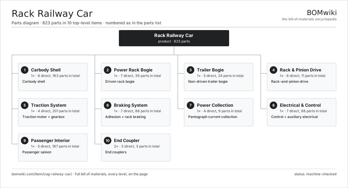
| # | Part | Qty | What it does |
|---|---|---|---|
| 1 | Carbody Shell 8 parts | 1× | Carbody shell |
| 2 | Power Rack Bogie 7 parts | 1× | Driven rack bogie |
| 3 | Trailer Bogie 5 parts | 1× | Non-driven trailer bogie |
| 4 | Rack & Pinion Drive 6 parts | 1× | Rack-and-pinion drive |
| 5 | Traction System 4 parts | 1× | Traction motor + gearbox |
| 6 | Braking System 7 parts | 1× | Adhesion + rack braking |
| 7 | Power Collection 4 parts | 1× | Pantograph current collection |
| 8 | Electrical & Control 7 parts | 1× | Control + auxiliary electrical |
| 9 | Passenger Interior 5 parts | 1× | Passenger saloon |
| 10 | End Coupler 3 parts | 2× | End couplers |
3D model
No 3D model yet. Have a CAD file of this? Add a 3D model. STL renders right on this page; STEP, FreeCAD, and OpenSCAD sources are welcome too (openly licensed, like all 3D models on BOMwiki).
Build & assembly graph
expand / collapse · shared sub-assemblies converge · links to related products · est. labourTap an assembly to expand/collapse · tap a part to open it · use “Open page” for any node · drag to pan, scroll to zoom.
Bill of materials for Rack Railway Car
10 top-level lines · 133 rows shown · 823 parts total · indented to 3 levels| # | Item / sub-assembly | Part no. | Qty/assy | Ext. qty | Parts | Type |
|---|---|---|---|---|---|---|
| 1 | Carbody Shell 8 parts | cog-railway-car-carbody | 1× | 1 | 163 | assembly |
| 1.1 | Underframe | cog-railway-car-underframe | 1× | 1 | · | part |
| 1.2 | Stepped Floor Pan | cog-railway-car-stepped-floor | 1× | 1 | · | part |
| 1.3 | Side Wall Panel | cog-railway-car-sidewall | 2× | 2 | · | part |
| 1.4 | Roof Panel | cog-railway-car-roof | 1× | 1 | · | part |
| 1.5 | End Wall | cog-railway-car-endwall | 2× | 2 | · | part |
| 1.6 | Side Window | cog-railway-car-window | 14× | 14 | · | part |
| 1.7 | Sliding Entrance Door 3 parts | cog-railway-car-door | 4× | 4 | 35 | assembly |
| 1.7.1 | Door Leaf & Track | cog-railway-car-door-leaf | 1× | 4 | · | part |
| 1.7.2 | Servo Motor 4 parts + deeper › | servo-motor | 1× | 4 | 24 | assembly |
| 1.7.3 | Door Control Unit 4 parts + deeper › | cog-railway-car-door-controller | 1× | 4 | 10 | assembly |
| 1.8 | Fastener Set | fastener-set | 2× | 2 | · | part |
| 2 | Power Rack Bogie 7 parts | cog-railway-car-power-bogie | 1× | 1 | 36 | assembly |
| 2.1 | Bogie Frame | cog-railway-car-bogie-frame | 1× | 1 | · | part |
| 2.2 | Adhesion Wheelset 3 parts | cog-railway-car-wheelset | 2× | 2 | 5 | assembly |
| 2.2.1 | Axle | cog-railway-car-axle | 1× | 2 | · | part |
| 2.2.2 | Flanged Wheel | cog-railway-car-wheel | 2× | 4 | · | part |
| 2.2.3 | Ball Bearing | ball-bearing | 2× | 4 | · | part |
| 2.3 | Pinion Shaft | cog-railway-car-pinion-shaft | 1× | 1 | · | part |
| 2.4 | Rack Guide Roller | cog-railway-car-rack-guide-roller | 4× | 4 | · | part |
| 2.5 | Coil Spring | coil-spring | 8× | 8 | · | part |
| 2.6 | Hydraulic Damper | cog-railway-car-damper | 4× | 4 | · | part |
| 2.7 | Ball Bearing | ball-bearing | 8× | 8 | · | part |
| 3 | Trailer Bogie 5 parts | cog-railway-car-trailer-bogie | 1× | 1 | 24 | assembly |
| 3.1 | Bogie Frame | cog-railway-car-bogie-frame | 1× | 1 | · | part |
| 3.2 | Adhesion Wheelset 3 parts | cog-railway-car-wheelset | 2× | 2 | 5 | assembly |
| 3.2.1 | Axle | cog-railway-car-axle | 1× | 2 | · | part |
| 3.2.2 | Flanged Wheel | cog-railway-car-wheel | 2× | 4 | · | part |
| 3.2.3 | Ball Bearing | ball-bearing | 2× | 4 | · | part |
| 3.3 | Rack-Brake Pinion | cog-railway-car-brake-pinion | 1× | 1 | · | part |
| 3.4 | Coil Spring | coil-spring | 8× | 8 | · | part |
| 3.5 | Hydraulic Damper | cog-railway-car-damper | 4× | 4 | · | part |
| 4 | Rack & Pinion Drive 6 parts | cog-railway-car-rack-drive | 1× | 1 | 11 | assembly |
| 4.1 | Drive Pinion (Cog Wheel) | cog-railway-car-drive-pinion | 1× | 1 | · | part |
| 4.2 | Pinion Shaft | cog-railway-car-pinion-shaft | 1× | 1 | · | part |
| 4.3 | Pinion Hub | cog-railway-car-pinion-hub | 1× | 1 | · | part |
| 4.4 | Ball Bearing | ball-bearing | 4× | 4 | · | part |
| 4.5 | Oil Seal | oil-seal | 2× | 2 | · | part |
| 4.6 | Mesh-Load Spring | cog-railway-car-rack-spring | 2× | 2 | · | part |
| 5 | Traction System 4 parts | cog-railway-car-traction | 1× | 1 | 201 | assembly |
| 5.1 | Traction Motor 5 parts | cog-railway-car-traction-motor | 1× | 1 | 26 | assembly |
| 5.1.1 | Stator Assembly 3 parts + deeper › | stator-assembly | 1× | 1 | 3 | assembly |
| 5.1.2 | Rotor Assembly 4 parts + deeper › | rotor-assembly | 1× | 1 | 19 | assembly |
| 5.1.3 | Motor Housing | cog-railway-car-motor-housing | 1× | 1 | · | part |
| 5.1.4 | Ball Bearing | ball-bearing | 2× | 2 | · | part |
| 5.1.5 | Motor Speed Sensor | cog-railway-car-speed-sensor | 1× | 1 | · | part |
| 5.2 | Reduction Gearbox 5 parts | cog-railway-car-gearbox | 1× | 1 | 10 | assembly |
| 5.2.1 | Helical Gear Pair | gear-pair | 2× | 2 | · | part |
| 5.2.2 | Gearbox Housing | gearbox-housing | 1× | 1 | · | part |
| 5.2.3 | Ball Bearing | ball-bearing | 4× | 4 | · | part |
| 5.2.4 | Oil Seal | oil-seal | 2× | 2 | · | part |
| 5.2.5 | Gear Oil | cog-railway-car-gear-oil | 1× | 1 | · | part |
| 5.3 | Traction Inverter 4 parts | cog-railway-car-inverter | 1× | 1 | 140 | assembly |
| 5.3.1 | IGBT Power Module | cog-railway-car-igbt-module | 6× | 6 | · | part |
| 5.3.2 | Inverter Control Board 4 parts + deeper › | cog-railway-car-inverter-control | 1× | 1 | 130 | assembly |
| 5.3.3 | DC-Link Capacitor | cog-railway-car-dc-link-cap | 3× | 3 | · | part |
| 5.3.4 | Inverter Housing | cog-railway-car-inverter-housing | 1× | 1 | · | part |
| 5.4 | Cooling Blower 2 parts | cog-railway-car-cooling-blower | 1× | 1 | 25 | assembly |
| 5.4.1 | Servo Motor 4 parts + deeper › | servo-motor | 1× | 1 | 24 | assembly |
| 5.4.2 | Blower Impeller | cog-railway-car-blower-impeller | 1× | 1 | · | part |
| 6 | Braking System 7 parts | cog-railway-car-braking | 1× | 1 | 88 | assembly |
| 6.1 | Rack Brake 3 parts | cog-railway-car-rack-brake | 1× | 1 | 4 | assembly |
| 6.1.1 | Rack-Brake Disc | cog-railway-car-rack-brake-disc | 1× | 1 | · | part |
| 6.1.2 | Brake Caliper & Pads | cog-railway-car-brake-caliper | 2× | 2 | · | part |
| 6.1.3 | O-Ring Set | oring-set | 1× | 1 | · | part |
| 6.2 | Emergency Rack Brake 4 parts | cog-railway-car-emergency-rack-brake | 1× | 1 | 8 | assembly |
| 6.2.1 | Coil Spring | coil-spring | 4× | 4 | · | part |
| 6.2.2 | Brake Caliper & Pads | cog-railway-car-brake-caliper | 2× | 2 | · | part |
| 6.2.3 | Overspeed Governor | cog-railway-car-overspeed-governor | 1× | 1 | · | part |
| 6.2.4 | Brake Air Cylinder | cog-railway-car-brake-cylinder | 1× | 1 | · | part |
| 6.3 | Wheel Disc Brake 3 parts | cog-railway-car-wheel-disc-brake | 4× | 4 | 3 | assembly |
| 6.3.1 | Wheel-Mounted Brake Disc | cog-railway-car-wheel-brake-disc | 1× | 4 | · | part |
| 6.3.2 | Brake Caliper & Pads | cog-railway-car-brake-caliper | 1× | 4 | · | part |
| 6.3.3 | Brake Air Cylinder | cog-railway-car-brake-cylinder | 1× | 4 | · | part |
| 6.4 | Rheostatic Brake Resistor 2 parts | cog-railway-car-rheostatic-brake | 1× | 1 | 5 | assembly |
| 6.4.1 | Brake Resistor Element | cog-railway-car-brake-resistor | 4× | 4 | · | part |
| 6.4.2 | Resistor Cooling Fan | cog-railway-car-resistor-fan | 1× | 1 | · | part |
| 6.5 | Air Compressor 3 parts | cog-railway-car-air-compressor | 1× | 1 | 27 | assembly |
| 6.5.1 | Servo Motor 4 parts + deeper › | servo-motor | 1× | 1 | 24 | assembly |
| 6.5.2 | Compressor Head | cog-railway-car-compressor-head | 1× | 1 | · | part |
| 6.5.3 | O-Ring Set | oring-set | 2× | 2 | · | part |
| 6.6 | Air Reservoir | cog-railway-car-air-reservoir | 2× | 2 | · | part |
| 6.7 | Brake Control Unit 5 parts | cog-railway-car-brake-control | 1× | 1 | 30 | assembly |
| 6.7.1 | Bare PCB | pcb-bare | 2× | 2 | · | part |
| 6.7.2 | Microcontroller | mcu | 2× | 2 | · | part |
| 6.7.3 | Pressure Sensor | pressure-sensor | 4× | 4 | · | part |
| 6.7.4 | Relay | relay | 6× | 6 | · | part |
| 6.7.5 | Connector | connector | 16× | 16 | · | part |
| 7 | Power Collection 4 parts | cog-railway-car-power-collection | 1× | 1 | 9 | assembly |
| 7.1 | Pantograph 4 parts | cog-railway-car-pantograph | 1× | 1 | 6 | assembly |
| 7.1.1 | Pantograph Frame | cog-railway-car-pan-frame | 1× | 1 | · | part |
| 7.1.2 | Carbon Contact Strip | cog-railway-car-contact-strip | 2× | 2 | · | part |
| 7.1.3 | Coil Spring | coil-spring | 2× | 2 | · | part |
| 7.1.4 | Pantograph Actuator | cog-railway-car-pan-actuator | 1× | 1 | · | part |
| 7.2 | High-Speed Line Breaker | cog-railway-car-line-breaker | 1× | 1 | · | part |
| 7.3 | Surge Arrester | cog-railway-car-surge-arrester | 1× | 1 | · | part |
| 7.4 | HV Roof Cable | cog-railway-car-roof-cable | 1× | 1 | · | part |
| 8 | Electrical & Control 7 parts | cog-railway-car-electrical | 1× | 1 | 98 | assembly |
| 8.1 | Vehicle Control Unit 4 parts | cog-railway-car-control-unit | 1× | 1 | 36 | assembly |
| 8.1.1 | Bare PCB | pcb-bare | 2× | 2 | · | part |
| 8.1.2 | Microcontroller | mcu | 2× | 2 | · | part |
| 8.1.3 | Relay | relay | 8× | 8 | · | part |
| 8.1.4 | Connector | connector | 24× | 24 | · | part |
| 8.2 | Auxiliary Power Converter 4 parts | cog-railway-car-aux-converter | 1× | 1 | 6 | assembly |
| 8.2.1 | Bare PCB | pcb-bare | 1× | 1 | · | part |
| 8.2.2 | IGBT Power Module | cog-railway-car-igbt-module | 2× | 2 | · | part |
| 8.2.3 | Power Supply | power-supply | 1× | 1 | · | part |
| 8.2.4 | DC-Link Capacitor | cog-railway-car-dc-link-cap | 2× | 2 | · | part |
| 8.3 | Control Battery | cog-railway-car-battery | 1× | 1 | · | part |
| 8.4 | Cab Display 3 parts | cog-railway-car-driver-display | 2× | 2 | 3 | assembly |
| 8.4.1 | LCD Panel | lcd-panel | 1× | 2 | · | part |
| 8.4.2 | Bare PCB | pcb-bare | 1× | 2 | · | part |
| 8.4.3 | Microcontroller | mcu | 1× | 2 | · | part |
| 8.5 | LED Light Fixture | cog-railway-car-led-fixture | 18× | 18 | · | part |
| 8.6 | Wire Bundle | wire-bundle | 1× | 1 | · | part |
| 8.7 | Connector | connector | 30× | 30 | · | part |
| 9 | Passenger Interior 5 parts | cog-railway-car-interior | 1× | 1 | 187 | assembly |
| 9.1 | Passenger Seat | cog-railway-car-seat | 56× | 56 | · | part |
| 9.2 | Wall & Ceiling Lining | cog-railway-car-lining | 2× | 2 | · | part |
| 9.3 | Grab Rail | cog-railway-car-grab-rail | 8× | 8 | · | part |
| 9.4 | Saloon Heater 3 parts | cog-railway-car-saloon-heater | 4× | 4 | 26 | assembly |
| 9.4.1 | Heating Element | heating-element | 1× | 4 | · | part |
| 9.4.2 | Servo Motor 4 parts + deeper › | servo-motor | 1× | 4 | 24 | assembly |
| 9.4.3 | Relay | relay | 1× | 4 | · | part |
| 9.5 | Driving Cab 4 parts | cog-railway-car-cab | 1× | 1 | 17 | assembly |
| 9.5.1 | Master Controller | cog-railway-car-master-controller | 1× | 1 | · | part |
| 9.5.2 | Cab Display 3 parts + deeper › | cog-railway-car-driver-display | 1× | 1 | 3 | assembly |
| 9.5.3 | Cab Seat | cog-railway-car-cab-seat | 1× | 1 | · | part |
| 9.5.4 | Connector | connector | 12× | 12 | · | part |
| 10 | End Coupler 3 parts | cog-railway-car-coupler | 2× | 2 | 3 | assembly |
| 10.1 | Coupler Head | cog-railway-car-coupler-head | 1× | 2 | · | part |
| 10.2 | Draft Gear | cog-railway-car-draft-gear | 1× | 2 | · | part |
| 10.3 | Fastener Set | fastener-set | 1× | 2 | · | part |
Related products
same domain, ranked by shared parts Automated People Mover
450 parts · shares 18 with this page
Automated People Mover
450 parts · shares 18 with this page
 Bus Rapid Transit Vehicle
4,251 parts · shares 18 with this page
Bus Rapid Transit Vehicle
4,251 parts · shares 18 with this page
 Commuter EMU
14,010 parts · shares 18 with this page
Commuter EMU
14,010 parts · shares 18 with this page
 Diesel Multiple Unit
12,609 parts · shares 18 with this page
Diesel Multiple Unit
12,609 parts · shares 18 with this page
 Electric Bus
4,481 parts · shares 18 with this page
Electric Bus
4,481 parts · shares 18 with this page
 Overhead Wire Maintenance Car
230 parts · shares 18 with this page
Overhead Wire Maintenance Car
230 parts · shares 18 with this page
Sourcing: possible vendors
Browse the supplier directory → Prices, MOQ, and lead times are algorithmic estimates, not quotes, and not claims about these companies. Company mappings are curated by keyword; est. price band $500k–$60M. How estimates work| Vendor | HQ | Specialty | MOQ | Lead time |
|---|---|---|---|---|
|
🇨🇳CRRC
crrcgc.cc ↗
|
Beijing, CN | Rolling stock & rail systems | made to order | 40–72 wks |
|
🇫🇷Alstom
alstom.com ↗
|
Saint-Ouen, FR | Rail rolling stock | made to order | 40–72 wks |
| mobility.siemens.com ↗ | Munich, DE | Rail systems | made to order | 40–72 wks |
| stadlerrail.com ↗ | Bussnang, CH | Rail rolling stock | made to order | 40–72 wks |
|
🇺🇸Wabtec
wabteccorp.com ↗
|
Pittsburgh, US | Rail equipment | made to order | 40–72 wks |
1,073-word article