Metro Car
ProductOverview
A Metro Car is one car of an electric multiple-unit subway train, carrying its own traction and control equipment so cars can be combined into trains of varying length. This car has an aluminium carbody riding on two bogies, takes power from a third rail or overhead wire, and is run by a train control and management system. It seats and stands passengers behind four sliding plug doors per side.
Carbody
The Aluminium Carbody is a welded aluminium-extrusion monocoque. It is built from an Underframe that carries the bogie and equipment loads, two Side Wall Panel panels, a Roof Structure, and two End Gangway end sections that connect to adjacent cars or form a cab end. Twelve Side Window panels glaze the sides, and the shell is assembled with a Fastener Set.
Bogies and running gear
The car runs on two bogies. The Motor Bogie is powered, carrying two Traction Motor units, while the Trailer Bogie carries none; both otherwise share the same structure. Each bogie is built on a Bogie Frame welded from a Bogie Frame Weldment and fitted with axle-box Ball Bearing bearings, an O-Ring Set, and a Fastener Set. Two Wheelset wheelsets per bogie each combine a Axle, two Monobloc Wheel monobloc wheels, and bearings. Ride comfort comes from a Air Spring secondary suspension and Primary Coil Spring coil primary suspension. Each Traction Motor is a 3-phase AC induction machine built from a Stator Assembly, a Rotor Assembly, a Final Drive Gear Unit final drive, and bearings; the gear unit itself uses a Helical Gear Pair. Braking is by Brake Disc & Caliper units combining a Wheel-mounted Brake Disc, a Brake Caliper, and Brake Pad pads.
Traction electronics
The Traction System converts line power into motor drive. A Current Collector picks up current through Third-Rail Collector Shoe third-rail shoes or a Pantograph. The Traction Inverter (VVVF) is a VVVF (variable voltage, variable frequency) drive built around IGBT Power Module power switches, DC-Link Capacitor capacitors, a Gate Driver IC, an Microcontroller, a Bare PCB, and a Inverter Cabinet. A smaller Auxiliary Inverter (SIV) supplies onboard loads, and a Line Filter Reactor smooths the incoming current.
Doors and interior
Each Sliding Plug Door is a bi-parting sliding plug door with two Door Leaf leaves, a Blower Motor operator, a Door Carriage Track carriage track, and a Door Control Unit built from a Bare PCB, an Microcontroller, a CAN Transceiver, and SMD Passive (R/C/L). The Interior fits eight Bench Seat benches, twelve Grab Pole poles, a Floor Covering covering, and Ceiling Panel panels.
Climate, lighting, and power
Two Roof HVAC Unit units handle climate, each with Blower Motor fans, a HVAC Compressor, control electronics, and Relay switching. The LED Lighting System system runs 16 LED Light Fixture fixtures off a Wire Bundle and Connector set. The Auxiliary Power group keeps low-voltage systems alive with an 12 V Battery, a BMS Board, and a Battery Charger that uses an IGBT Power Module, DC-Link Capacitor capacitors, and a Inverter Cabinet.
Control, coupling, and braking
The Train Control & Management supervises the car. Its TCMS Computer (built from Bare PCB boards, a Compute SoC Module, CAN Transceiver interfaces, Relay outputs, and SMD Passive (R/C/L)) ties together the ATC/ATO Signaling Board signaling computer, Camera Module CCTV, Speaker public address, and LCD Panel passenger displays over a Wire Bundle. At each end an Automatic Coupler joins cars with a Coupler Head, a Draft Gear, and an electric Connector block. The Brake Control Unit unit commands braking through a Bare PCB, an Microcontroller, Relay outputs, Brake Control Valve valves, and an Air Reservoir.
Power flow
In service the car draws current through the Current Collector, feeds it through the Line Filter Reactor to smooth ripple, and into the Traction Inverter (VVVF). The inverter's IGBT Power Module switches, paced by the Gate Driver IC under the inverter Microcontroller, synthesise three-phase AC at the frequency and voltage the Traction Motor units need for the demanded speed, with the DC-Link Capacitor bank stabilising the link. The same supply runs the Auxiliary Inverter (SIV) for lighting, doors, and HVAC, and charges the 12 V Battery through the Battery Charger so control systems survive a loss of line power.
Braking and control coordination
The Train Control & Management and Brake Control Unit work together to stop the car. For most braking the Traction Inverter (VVVF) runs the motors as generators, slowing the car and returning energy to the line, while the Brake Disc & Caliper friction brakes blend in at low speed and provide holding force, commanded through the Brake Control Valve valves and Air Reservoir. Over it all the ATC/ATO Signaling Board enforces signaling limits, and the TCMS Computer arbitrates between traction, braking, doors, and auxiliaries so the car responds safely to driver or automatic-train-operation commands.
Metro Car parts and their functions
12 top-level parts · 1,156 parts in total · full bill of materials below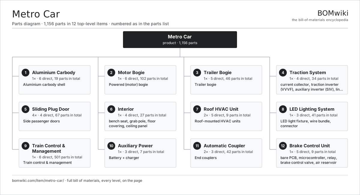
| # | Part | Qty | What it does |
|---|---|---|---|
| 1 | Aluminium Carbody 6 parts | 1× | Aluminium carbody shell |
| 2 | Motor Bogie 6 parts | 1× | Powered (motor) bogie |
| 3 | Trailer Bogie 5 parts | 1× | Trailer bogie |
| 4 | Traction System 4 parts | 1× | Current collection, traction inverter, auxiliary inverter, and line filter. |
| 5 | Sliding Plug Door 4 parts | 4× | Side passenger doors |
| 6 | Interior 4 parts | 1× | |
| 7 | Roof HVAC Unit 5 parts | 2× | Roof-mounted HVAC units |
| 8 | LED Lighting System 3 parts | 1× | |
| 9 | Train Control & Management 6 parts | 1× | Train control & management |
| 10 | Auxiliary Power 3 parts | 1× | Battery + charger |
| 11 | Automatic Coupler 3 parts | 2× | End couplers |
| 12 | Brake Control Unit 5 parts | 1× |
Diagrams & photos


3D model
No 3D model yet. Have a CAD file of this? Add a 3D model. STL renders right on this page; STEP, FreeCAD, and OpenSCAD sources are welcome too (openly licensed, like all 3D models on BOMwiki).
Build & assembly graph
expand / collapse · shared sub-assemblies converge · links to related products · est. labourTap an assembly to expand/collapse · tap a part to open it · use “Open page” for any node · drag to pan, scroll to zoom.
Bill of materials for Metro Car
12 top-level lines · 124 rows shown · 1,156 parts total · indented to 3 levels| # | Item / sub-assembly | Part no. | Qty/assy | Ext. qty | Parts | Type |
|---|---|---|---|---|---|---|
| 1 | Aluminium Carbody 6 parts | metro-car-carbody | 1× | 1 | 19 | assembly |
| 1.1 | Underframe | metro-car-underframe | 1× | 1 | · | part |
| 1.2 | Side Wall Panel | metro-car-sidewall | 2× | 2 | · | part |
| 1.3 | Roof Structure | metro-car-roof-structure | 1× | 1 | · | part |
| 1.4 | End Gangway | metro-car-gangway | 2× | 2 | · | part |
| 1.5 | Side Window | metro-car-window | 12× | 12 | · | part |
| 1.6 | Fastener Set | fastener-set | 1× | 1 | · | part |
| 2 | Motor Bogie 6 parts | metro-car-bogie-motor | 1× | 1 | 102 | assembly |
| 2.1 | Bogie Frame 4 parts | metro-car-bogie-frame | 1× | 1 | 14 | assembly |
| 2.1.1 | Bogie Frame Weldment | metro-car-frame-weldment | 1× | 1 | · | part |
| 2.1.2 | Ball Bearing | ball-bearing | 8× | 8 | · | part |
| 2.1.3 | Fastener Set | fastener-set | 1× | 1 | · | part |
| 2.1.4 | O-Ring Set | oring-set | 4× | 4 | · | part |
| 2.2 | Traction Motor 4 parts | metro-car-traction-motor | 2× | 2 | 28 | assembly |
| 2.2.1 | Stator Assembly 3 parts + deeper › | stator-assembly | 1× | 2 | 3 | assembly |
| 2.2.2 | Rotor Assembly 4 parts + deeper › | rotor-assembly | 1× | 2 | 19 | assembly |
| 2.2.3 | Final Drive Gear Unit 3 parts + deeper › | metro-car-gear-unit | 1× | 2 | 4 | assembly |
| 2.2.4 | Ball Bearing | ball-bearing | 2× | 4 | · | part |
| 2.3 | Wheelset 3 parts | metro-car-wheelset | 2× | 2 | 5 | assembly |
| 2.3.1 | Axle | metro-car-axle | 1× | 2 | · | part |
| 2.3.2 | Monobloc Wheel | metro-car-wheel | 2× | 4 | · | part |
| 2.3.3 | Ball Bearing | ball-bearing | 2× | 4 | · | part |
| 2.4 | Air Spring | metro-car-air-spring | 2× | 2 | · | part |
| 2.5 | Primary Coil Spring | metro-car-primary-spring | 4× | 4 | · | part |
| 2.6 | Brake Disc & Caliper 3 parts | metro-car-disc-brake | 4× | 4 | 4 | assembly |
| 2.6.1 | Wheel-mounted Brake Disc | metro-car-brake-rotor | 1× | 4 | · | part |
| 2.6.2 | Brake Caliper | metro-car-brake-caliper | 1× | 4 | · | part |
| 2.6.3 | Brake Pad | metro-car-brake-pad | 2× | 8 | · | part |
| 3 | Trailer Bogie 5 parts | metro-car-bogie-trailer | 1× | 1 | 46 | assembly |
| 3.1 | Bogie Frame 4 parts | metro-car-bogie-frame | 1× | 1 | 14 | assembly |
| 3.1.1 | Bogie Frame Weldment | metro-car-frame-weldment | 1× | 1 | · | part |
| 3.1.2 | Ball Bearing | ball-bearing | 8× | 8 | · | part |
| 3.1.3 | Fastener Set | fastener-set | 1× | 1 | · | part |
| 3.1.4 | O-Ring Set | oring-set | 4× | 4 | · | part |
| 3.2 | Wheelset 3 parts | metro-car-wheelset | 2× | 2 | 5 | assembly |
| 3.2.1 | Axle | metro-car-axle | 1× | 2 | · | part |
| 3.2.2 | Monobloc Wheel | metro-car-wheel | 2× | 4 | · | part |
| 3.2.3 | Ball Bearing | ball-bearing | 2× | 4 | · | part |
| 3.3 | Air Spring | metro-car-air-spring | 2× | 2 | · | part |
| 3.4 | Primary Coil Spring | metro-car-primary-spring | 4× | 4 | · | part |
| 3.5 | Brake Disc & Caliper 3 parts | metro-car-disc-brake | 4× | 4 | 4 | assembly |
| 3.5.1 | Wheel-mounted Brake Disc | metro-car-brake-rotor | 1× | 4 | · | part |
| 3.5.2 | Brake Caliper | metro-car-brake-caliper | 1× | 4 | · | part |
| 3.5.3 | Brake Pad | metro-car-brake-pad | 2× | 8 | · | part |
| 4 | Traction System 4 parts | metro-car-traction-system | 1× | 1 | 34 | assembly |
| 4.1 | Current Collector 3 parts | metro-car-collector | 1× | 1 | 4 | assembly |
| 4.1.1 | Third-Rail Collector Shoe | metro-car-collector-shoe | 2× | 2 | · | part |
| 4.1.2 | Pantograph | metro-car-pantograph | 1× | 1 | · | part |
| 4.1.3 | Fastener Set | fastener-set | 1× | 1 | · | part |
| 4.2 | Traction Inverter (VVVF) 6 parts | metro-car-traction-inverter | 1× | 1 | 19 | assembly |
| 4.2.1 | IGBT Power Module | igbt-module | 6× | 6 | · | part |
| 4.2.2 | DC-Link Capacitor | dc-link-cap | 4× | 4 | · | part |
| 4.2.3 | Bare PCB | pcb-bare | 1× | 1 | · | part |
| 4.2.4 | Microcontroller | mcu | 1× | 1 | · | part |
| 4.2.5 | Gate Driver IC | gate-driver-ic | 6× | 6 | · | part |
| 4.2.6 | Inverter Cabinet | metro-car-inverter-cabinet | 1× | 1 | · | part |
| 4.3 | Auxiliary Inverter (SIV) 5 parts | metro-car-aux-inverter | 1× | 1 | 10 | assembly |
| 4.3.1 | IGBT Power Module | igbt-module | 3× | 3 | · | part |
| 4.3.2 | DC-Link Capacitor | dc-link-cap | 2× | 2 | · | part |
| 4.3.3 | Bare PCB | pcb-bare | 1× | 1 | · | part |
| 4.3.4 | Gate Driver IC | gate-driver-ic | 3× | 3 | · | part |
| 4.3.5 | Inverter Cabinet | metro-car-inverter-cabinet | 1× | 1 | · | part |
| 4.4 | Line Filter Reactor | metro-car-line-filter | 1× | 1 | · | part |
| 5 | Sliding Plug Door 4 parts | metro-car-door-system | 4× | 4 | 67 | assembly |
| 5.1 | Door Leaf | metro-car-door-leaf | 2× | 8 | · | part |
| 5.2 | Blower Motor | blower-motor | 1× | 4 | · | part |
| 5.3 | Door Control Unit 4 parts | metro-car-door-controller | 1× | 4 | 63 | assembly |
| 5.3.1 | Bare PCB | pcb-bare | 1× | 4 | · | part |
| 5.3.2 | Microcontroller | mcu | 1× | 4 | · | part |
| 5.3.3 | CAN Transceiver | can-transceiver | 1× | 4 | · | part |
| 5.3.4 | SMD Passive (R/C/L) | smd-passives | 60× | 240 | · | part |
| 5.4 | Door Carriage Track | metro-car-door-track | 1× | 4 | · | part |
| 6 | Interior 4 parts | metro-car-interior | 1× | 1 | 27 | assembly |
| 6.1 | Bench Seat | metro-car-bench-seat | 8× | 8 | · | part |
| 6.2 | Grab Pole | metro-car-grab-pole | 12× | 12 | · | part |
| 6.3 | Floor Covering | metro-car-flooring | 1× | 1 | · | part |
| 6.4 | Ceiling Panel | metro-car-ceiling-panel | 6× | 6 | · | part |
| 7 | Roof HVAC Unit 5 parts | metro-car-hvac-roof | 2× | 2 | 9 | assembly |
| 7.1 | Blower Motor | blower-motor | 2× | 4 | · | part |
| 7.2 | HVAC Compressor | metro-car-compressor | 1× | 2 | · | part |
| 7.3 | Bare PCB | pcb-bare | 1× | 2 | · | part |
| 7.4 | Microcontroller | mcu | 1× | 2 | · | part |
| 7.5 | Relay | relay | 4× | 8 | · | part |
| 8 | LED Lighting System 3 parts | metro-car-lighting | 1× | 1 | 41 | assembly |
| 8.1 | LED Light Fixture | metro-car-led-fixture | 16× | 16 | · | part |
| 8.2 | Wire Bundle | wire-bundle | 1× | 1 | · | part |
| 8.3 | Connector | connector | 24× | 24 | · | part |
| 9 | Train Control & Management 6 parts | metro-car-tcms | 1× | 1 | 501 | assembly |
| 9.1 | TCMS Computer 5 parts | metro-car-tcms-computer | 1× | 1 | 315 | assembly |
| 9.1.1 | Bare PCB | pcb-bare | 2× | 2 | · | part |
| 9.1.2 | Compute SoC Module | soc-module | 1× | 1 | · | part |
| 9.1.3 | CAN Transceiver | can-transceiver | 4× | 4 | · | part |
| 9.1.4 | Relay | relay | 8× | 8 | · | part |
| 9.1.5 | SMD Passive (R/C/L) | smd-passives | 300× | 300 | · | part |
| 9.2 | ATC/ATO Signaling Board 4 parts | metro-car-atc-board | 1× | 1 | 155 | assembly |
| 9.2.1 | Bare PCB | pcb-bare | 1× | 1 | · | part |
| 9.2.2 | Microcontroller | mcu | 2× | 2 | · | part |
| 9.2.3 | CAN Transceiver | can-transceiver | 2× | 2 | · | part |
| 9.2.4 | SMD Passive (R/C/L) | smd-passives | 150× | 150 | · | part |
| 9.3 | Camera Module 3 parts | camera-module | 6× | 6 | 3 | assembly |
| 9.3.1 | CMOS Image Sensor | image-sensor | 1× | 6 | · | part |
| 9.3.2 | Lens Assembly | camera-lens | 1× | 6 | · | part |
| 9.3.3 | Bare PCB | pcb-bare | 1× | 6 | · | part |
| 9.4 | Speaker | speaker | 8× | 8 | · | part |
| 9.5 | LCD Panel | lcd-panel | 4× | 4 | · | part |
| 9.6 | Wire Bundle | wire-bundle | 1× | 1 | · | part |
| 10 | Auxiliary Power 3 parts | metro-car-aux-power | 1× | 1 | 7 | assembly |
| 10.1 | 12 V Battery | lv-battery | 1× | 1 | · | part |
| 10.2 | BMS Board | bms-board | 1× | 1 | · | part |
| 10.3 | Battery Charger 4 parts | metro-car-battery-charger | 1× | 1 | 5 | assembly |
| 10.3.1 | Bare PCB | pcb-bare | 1× | 1 | · | part |
| 10.3.2 | IGBT Power Module | igbt-module | 1× | 1 | · | part |
| 10.3.3 | DC-Link Capacitor | dc-link-cap | 2× | 2 | · | part |
| 10.3.4 | Inverter Cabinet | metro-car-inverter-cabinet | 1× | 1 | · | part |
| 11 | Automatic Coupler 3 parts | metro-car-coupler | 2× | 2 | 42 | assembly |
| 11.1 | Coupler Head | metro-car-coupler-head | 1× | 2 | · | part |
| 11.2 | Draft Gear | metro-car-draft-gear | 1× | 2 | · | part |
| 11.3 | Connector | connector | 40× | 80 | · | part |
| 12 | Brake Control Unit 5 parts | metro-car-brake-control | 1× | 1 | 9 | assembly |
| 12.1 | Bare PCB | pcb-bare | 1× | 1 | · | part |
| 12.2 | Microcontroller | mcu | 1× | 1 | · | part |
| 12.3 | Relay | relay | 4× | 4 | · | part |
| 12.4 | Brake Control Valve | metro-car-brake-valve | 2× | 2 | · | part |
| 12.5 | Air Reservoir | metro-car-air-reservoir | 1× | 1 | · | part |
Something wrong in this list? Report a problem with this BOM.
Related products
same domain, ranked by shared parts Tram
705 parts · shares 18 with this page
 High-Speed Trainset
1,445,128 parts · shares 19 with this page
 Electric Locomotive
2,774 parts · shares 17 with this page
 Commuter EMU
14,010 parts · shares 17 with this page
 Diesel-Electric Locomotive
181,216 parts · shares 17 with this page
 Passenger Locomotive
10,641 parts · shares 17 with this page
Sourcing: possible vendors
Browse the supplier directory → Prices, MOQ, and lead times are algorithmic estimates, not quotes, and not claims about these companies. Company mappings are curated by keyword; est. price band $500k–$60M. How estimates work| Vendor | HQ | Specialty | MOQ | Lead time |
|---|---|---|---|---|
|
🇨🇳CRRC
crrcgc.cc ↗
|
Beijing, CN | Rolling stock & rail systems | made to order | 40–72 wks |
|
🇫🇷Alstom
alstom.com ↗
|
Saint-Ouen, FR | Rail rolling stock | made to order | 40–72 wks |
| mobility.siemens.com ↗ | Munich, DE | Rail systems | made to order | 40–72 wks |
| stadlerrail.com ↗ | Bussnang, CH | Rail rolling stock | made to order | 40–72 wks |
|
🇺🇸Wabtec
wabteccorp.com ↗
|
Pittsburgh, US | Rail equipment | made to order | 40–72 wks |
893-word article