Catenary Maintenance Vehicle
ProductOverview
A catenary maintenance vehicle services the overhead contact-line equipment that supplies power to electric trains. The contact wire, messenger wire, registration arms, and tensioning gear all sit several metres above the track and need regular inspection, adjustment, and repair. Rather than erect scaffolding, this vehicle drives to the worksite on its own wheels and raises an insulated work platform up to the wires, letting a crew reach the catenary directly while standing on a stable, height-adjustable basket.
Because the work happens close to live or recently isolated high-voltage equipment, insulation and stability dominate the design. The platform is electrically isolated from the chassis, and the whole vehicle is built on a Rail Chassis & Carbody riding on two Railway Bogie units with a driving Driving Cab for road moves.
How it works
The Diesel Engine provides traction and drives the Hydraulic System, whose Hydraulic Pump Unit feeds every actuator on the vehicle. The Aerial Work Platform is the working heart: an insulated Articulating Boom lifted and extended by Boom Hydraulic Cylinder actuators, turned by a Slew / Rotation Drive so the Insulated Work Basket can be placed anywhere around the vehicle. Before lifting, the crew deploys the Stabiliser Outrigger stabilisers to take the load off the bogies and hold the vehicle steady.
For the actual catenary work, the Catenary Measuring & Tensioning Tools package combines a Measuring Pantograph that reads contact-wire height and stagger against the track, and Wire Tensioning Winch units that re-tension wires to specification. A Auxiliary Generator supplies power tools and lighting on the open deck independent of the traction engine, and a 12 V Battery bank starts the engine and holds up control and lighting circuits. The driver supervises road and platform operation from the Cab Control Display in the cab.
Catenary Maintenance Vehicle parts and their functions
9 top-level parts · 576 parts in total · full bill of materials below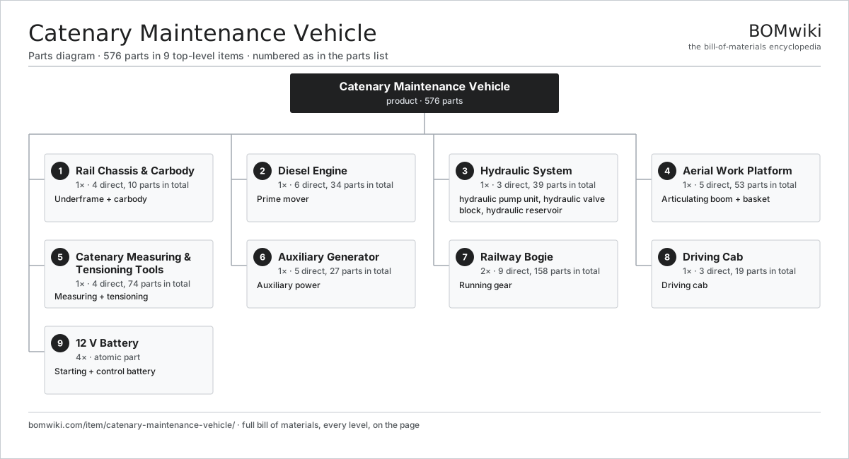
| # | Part | Qty | What it does |
|---|---|---|---|
| 1 | Rail Chassis & Carbody 4 parts | 1× | Underframe + carbody |
| 2 | Diesel Engine 6 parts | 1× | Prime mover |
| 3 | Hydraulic System 3 parts | 1× | Pumps and valves powering the boom, outriggers, and platform actuators. |
| 4 | Aerial Work Platform 5 parts | 1× | Articulating boom + basket |
| 5 | Catenary Measuring & Tensioning Tools 4 parts | 1× | Measuring + tensioning |
| 6 | Auxiliary Generator 5 parts | 1× | Auxiliary power |
| 7 | Railway Bogie 9 parts | 2× | Running gear |
| 8 | Driving Cab 3 parts | 1× | Driving cab |
| 9 | 12 V Battery | 4× | Starting + control battery |
3D model
No 3D model yet. Have a CAD file of this? Add a 3D model. STL renders right on this page; STEP, FreeCAD, and OpenSCAD sources are welcome too (openly licensed, like all 3D models on BOMwiki).
Build & assembly graph
expand / collapse · shared sub-assemblies converge · links to related products · est. labourTap an assembly to expand/collapse · tap a part to open it · use “Open page” for any node · drag to pan, scroll to zoom.
Bill of materials for Catenary Maintenance Vehicle
9 top-level lines · 151 rows shown · 576 parts total · indented to 3 levels| # | Item / sub-assembly | Part no. | Qty/assy | Ext. qty | Parts | Type |
|---|---|---|---|---|---|---|
| 1 | Rail Chassis & Carbody 4 parts | cmv-rail-chassis | 1× | 1 | 10 | assembly |
| 1.1 | Welded Steel Underframe | cmv-underframe | 1× | 1 | · | part |
| 1.2 | Working Deck Platform | cmv-deck | 1× | 1 | · | part |
| 1.3 | Automatic Coupler | cmv-coupler | 2× | 2 | · | part |
| 1.4 | Fastener Set | fastener-set | 6× | 6 | · | part |
| 2 | Diesel Engine 6 parts | cmv-diesel-engine | 1× | 1 | 34 | assembly |
| 2.1 | Engine Block | cmv-engine-block | 1× | 1 | · | part |
| 2.2 | Piston Assembly 3 parts | cmv-piston-assembly | 6× | 6 | 3 | assembly |
| 2.2.1 | Piston | cmv-piston | 1× | 6 | · | part |
| 2.2.2 | Connecting Rod | cmv-conrod | 1× | 6 | · | part |
| 2.2.3 | Piston Ring Set | cmv-piston-rings | 1× | 6 | · | part |
| 2.3 | Crankshaft | cmv-crankshaft | 1× | 1 | · | part |
| 2.4 | Turbocharger 3 parts | cmv-turbocharger | 1× | 1 | 5 | assembly |
| 2.4.1 | Turbine/Compressor Wheel | cmv-turbine-wheel | 1× | 1 | · | part |
| 2.4.2 | Ball Bearing | ball-bearing | 2× | 2 | · | part |
| 2.4.3 | Oil Seal | oil-seal | 2× | 2 | · | part |
| 2.5 | Fuel Injection System 3 parts | cmv-fuel-system | 1× | 1 | 8 | assembly |
| 2.5.1 | Fuel Pump | cmv-fuel-pump | 1× | 1 | · | part |
| 2.5.2 | Fuel Injector | cmv-fuel-injector | 6× | 6 | · | part |
| 2.5.3 | Diesel Fuel Tank | cmv-fuel-tank | 1× | 1 | · | part |
| 2.6 | Engine Radiator | cmv-radiator | 1× | 1 | · | part |
| 3 | Hydraulic System 3 parts | cmv-hydraulic-system | 1× | 1 | 39 | assembly |
| 3.1 | Hydraulic Pump Unit 4 parts | cmv-hydraulic-pump | 1× | 1 | 25 | assembly |
| 3.1.1 | Stator Assembly 3 parts + deeper › | stator-assembly | 1× | 1 | 3 | assembly |
| 3.1.2 | Rotor Assembly 4 parts + deeper › | rotor-assembly | 1× | 1 | 19 | assembly |
| 3.1.3 | Ball Bearing | ball-bearing | 2× | 2 | · | part |
| 3.1.4 | O-Ring Set | oring-set | 1× | 1 | · | part |
| 3.2 | Hydraulic Valve Block 3 parts | cmv-valve-block | 1× | 1 | 13 | assembly |
| 3.2.1 | Manifold Valve Body | cmv-valve-body | 1× | 1 | · | part |
| 3.2.2 | Relay | relay | 10× | 10 | · | part |
| 3.2.3 | O-Ring Set | oring-set | 2× | 2 | · | part |
| 3.3 | Hydraulic Reservoir | cmv-hydraulic-tank | 1× | 1 | · | part |
| 4 | Aerial Work Platform 5 parts | cmv-aerial-platform | 1× | 1 | 53 | assembly |
| 4.1 | Articulating Boom 3 parts | cmv-articulating-boom | 1× | 1 | 7 | assembly |
| 4.1.1 | Boom Section | cmv-boom-section | 3× | 3 | · | part |
| 4.1.2 | Boom Pivot Pin | cmv-boom-pivot | 2× | 2 | · | part |
| 4.1.3 | Fastener Set | fastener-set | 2× | 2 | · | part |
| 4.2 | Boom Hydraulic Cylinder 3 parts | cmv-boom-cylinder | 3× | 3 | 4 | assembly |
| 4.2.1 | Cylinder Tube | cmv-cylinder-tube | 1× | 3 | · | part |
| 4.2.2 | Cylinder Rod | cmv-cylinder-rod | 1× | 3 | · | part |
| 4.2.3 | O-Ring Set | oring-set | 2× | 6 | · | part |
| 4.3 | Slew / Rotation Drive 4 parts | cmv-rotation-drive | 1× | 1 | 25 | assembly |
| 4.3.1 | Stator Assembly 3 parts + deeper › | stator-assembly | 1× | 1 | 3 | assembly |
| 4.3.2 | Rotor Assembly 4 parts + deeper › | rotor-assembly | 1× | 1 | 19 | assembly |
| 4.3.3 | Ball Bearing | ball-bearing | 2× | 2 | · | part |
| 4.3.4 | Helical Gear Pair | gear-pair | 1× | 1 | · | part |
| 4.4 | Insulated Work Basket | cmv-work-basket | 1× | 1 | · | part |
| 4.5 | Stabiliser Outrigger 2 parts | cmv-outrigger | 4× | 4 | 2 | assembly |
| 4.5.1 | Outrigger Leg | cmv-outrigger-leg | 1× | 4 | · | part |
| 4.5.2 | Outrigger Cylinder | cmv-outrigger-cylinder | 1× | 4 | · | part |
| 5 | Catenary Measuring & Tensioning Tools 4 parts | cmv-catenary-tools | 1× | 1 | 74 | assembly |
| 5.1 | Measuring Pantograph 3 parts | cmv-measuring-pantograph | 1× | 1 | 5 | assembly |
| 5.1.1 | Pantograph Frame | cmv-pantograph-frame | 1× | 1 | · | part |
| 5.1.2 | Carbon Contact Strip | cmv-contact-strip | 2× | 2 | · | part |
| 5.1.3 | Wire Geometry Sensor | cmv-geometry-sensor | 2× | 2 | · | part |
| 5.2 | Wire Tensioning Winch 4 parts | cmv-tensioning-winch | 2× | 2 | 25 | assembly |
| 5.2.1 | Stator Assembly 3 parts + deeper › | stator-assembly | 1× | 2 | 3 | assembly |
| 5.2.2 | Rotor Assembly 4 parts + deeper › | rotor-assembly | 1× | 2 | 19 | assembly |
| 5.2.3 | Helical Gear Pair | gear-pair | 1× | 2 | · | part |
| 5.2.4 | Ball Bearing | ball-bearing | 2× | 4 | · | part |
| 5.3 | Wire Geometry Sensor | cmv-geometry-sensor | 4× | 4 | · | part |
| 5.4 | Tool Control Board 4 parts | cmv-tool-pcb | 1× | 1 | 15 | assembly |
| 5.4.1 | Bare PCB | pcb-bare | 1× | 1 | · | part |
| 5.4.2 | Microcontroller | mcu | 1× | 1 | · | part |
| 5.4.3 | Wire Bundle | wire-bundle | 1× | 1 | · | part |
| 5.4.4 | Connector | connector | 12× | 12 | · | part |
| 6 | Auxiliary Generator 5 parts | cmv-generator | 1× | 1 | 27 | assembly |
| 6.1 | Stator Assembly 3 parts | stator-assembly | 1× | 1 | 3 | assembly |
| 6.1.1 | Stator Core (laminations) | stator-core | 1× | 1 | · | part |
| 6.1.2 | Copper Winding | copper-winding | 1× | 1 | · | part |
| 6.1.3 | Slot Insulation | stator-insulation | 1× | 1 | · | part |
| 6.2 | Rotor Assembly 4 parts | rotor-assembly | 1× | 1 | 19 | assembly |
| 6.2.1 | Rotor Shaft | rotor-shaft | 1× | 1 | · | part |
| 6.2.2 | Rotor Core | rotor-core | 1× | 1 | · | part |
| 6.2.3 | Neodymium Magnet | neodymium-magnet | 16× | 16 | · | part |
| 6.2.4 | Ball Bearing | ball-bearing | 1× | 1 | · | part |
| 6.3 | Copper Winding | copper-winding | 2× | 2 | · | part |
| 6.4 | Ball Bearing | ball-bearing | 2× | 2 | · | part |
| 6.5 | Generator Frame | cmv-generator-frame | 1× | 1 | · | part |
| 7 | Railway Bogie 9 parts | bogie | 2× | 2 | 158 | product |
| 7.1 | Bogie frame 8 parts | bg-bogie-frame | 1× | 2 | 21 | assembly |
| 7.1.1 | Side frame | bg-side-frame | 2× | 4 | · | part |
| 7.1.2 | Transom | bg-transom | 2× | 4 | · | part |
| 7.1.3 | Bolster | bg-bolster | 1× | 2 | · | part |
| 7.1.4 | Centre pivot | bg-centre-pivot | 1× | 2 | · | part |
| 7.1.5 | Side bearer | bg-side-bearer | 2× | 4 | · | part |
| 7.1.6 | Lifting lug | bg-lifting-lug | 4× | 8 | · | part |
| 7.1.7 | Frame gusset | bg-frame-gusset | 8× | 16 | · | part |
| 7.1.8 | Fastener Set | fastener-set | 1× | 2 | · | part |
| 7.2 | Wheelset 6 parts | bg-wheelset | 2× | 4 | 23 | assembly |
| 7.2.1 | Axle | bg-axle | 1× | 4 | · | part |
| 7.2.2 | Wheel | bg-wheel | 2× | 8 | · | part |
| 7.2.3 | Axlebox 6 parts + deeper › | bg-axlebox | 2× | 8 | 8 | assembly |
| 7.2.4 | Earth brush | bg-earth-brush | 1× | 4 | · | part |
| 7.2.5 | Axle end cap | bg-axle-end-cap | 2× | 8 | · | part |
| 7.2.6 | Gear wheel | bg-gear-wheel | 1× | 4 | · | part |
| 7.3 | Primary suspension 6 parts | bg-primary-suspension | 2× | 4 | 10 | assembly |
| 7.3.1 | Coil Spring | coil-spring | 2× | 8 | · | part |
| 7.3.2 | Rubber chevron | bg-rubber-chevron | 2× | 8 | · | part |
| 7.3.3 | Primary damper | bg-primary-damper | 1× | 4 | · | part |
| 7.3.4 | Axlebox guide | bg-axlebox-guide | 2× | 8 | · | part |
| 7.3.5 | Spring cap | bg-spring-cap | 2× | 8 | · | part |
| 7.3.6 | Fastener Set | fastener-set | 1× | 4 | · | part |
| 7.4 | Secondary suspension 8 parts | bg-secondary-suspension | 1× | 2 | 18 | assembly |
| 7.4.1 | Air spring | bg-air-spring | 2× | 4 | · | part |
| 7.4.2 | Bolster spring | bg-bolster-spring | 4× | 8 | · | part |
| 7.4.3 | Lateral damper | bg-lateral-damper | 2× | 4 | · | part |
| 7.4.4 | Vertical damper | bg-vertical-damper | 4× | 8 | · | part |
| 7.4.5 | Traction rod | bg-traction-rod | 2× | 4 | · | part |
| 7.4.6 | Anti-roll bar | bg-anti-roll-bar | 1× | 2 | · | part |
| 7.4.7 | Levelling valve | bg-levelling-valve | 2× | 4 | · | part |
| 7.4.8 | Fastener Set | fastener-set | 1× | 2 | · | part |
| 7.5 | Brake equipment 7 parts | bg-brake-equipment | 1× | 2 | 29 | assembly |
| 7.5.1 | Brake Disc (rotor) | brake-disc | 4× | 8 | · | part |
| 7.5.2 | Brake caliper | bg-brake-caliper | 4× | 8 | · | part |
| 7.5.3 | Brake cylinder | bg-brake-cylinder | 4× | 8 | · | part |
| 7.5.4 | Brake Pad Set | brake-pad-set | 4× | 8 | · | part |
| 7.5.5 | Slack adjuster | bg-slack-adjuster | 4× | 8 | · | part |
| 7.5.6 | Brake hose | bg-brake-hose | 8× | 16 | · | part |
| 7.5.7 | Fastener Set | fastener-set | 1× | 2 | · | part |
| 7.6 | Traction package 8 parts | bg-traction-package | 1× | 2 | 12 | assembly |
| 7.6.1 | Traction motor | bg-traction-motor | 1× | 2 | · | part |
| 7.6.2 | Motor mount | bg-motor-mount | 1× | 2 | · | part |
| 7.6.3 | Gearbox | bg-gearbox | 1× | 2 | · | part |
| 7.6.4 | Pinion | bg-pinion | 1× | 2 | · | part |
| 7.6.5 | Flexible coupling | bg-flexible-coupling | 1× | 2 | · | part |
| 7.6.6 | Ball Bearing | ball-bearing | 4× | 8 | · | part |
| 7.6.7 | Oil Seal | oil-seal | 2× | 4 | · | part |
| 7.6.8 | Fastener Set | fastener-set | 1× | 2 | · | part |
| 7.7 | Sandbox 3 parts | bg-sandbox | 2× | 4 | 3 | assembly |
| 7.7.1 | Sand hopper | bg-sand-hopper | 1× | 4 | · | part |
| 7.7.2 | Sand nozzle | bg-sand-nozzle | 1× | 4 | · | part |
| 7.7.3 | Sand valve | bg-sand-valve | 1× | 4 | · | part |
| 7.8 | Flange lubricator 2 parts | bg-flange-lubricator | 2× | 4 | 2 | assembly |
| 7.8.1 | Grease reservoir | bg-grease-reservoir | 1× | 4 | · | part |
| 7.8.2 | Applicator nozzle | bg-applicator-nozzle | 1× | 4 | · | part |
| 7.9 | Wheel slide sensor | bg-wheel-slide-sensor | 2× | 4 | · | part |
| 8 | Driving Cab 3 parts | cmv-cab | 1× | 1 | 19 | assembly |
| 8.1 | Seat Assembly 5 parts | seat-assembly | 2× | 2 | 7 | assembly |
| 8.1.1 | Seat Frame | seat-frame | 1× | 2 | · | part |
| 8.1.2 | Seat Foam | seat-foam | 2× | 4 | · | part |
| 8.1.3 | Seat Cover | seat-cover | 1× | 2 | · | part |
| 8.1.4 | Seat Motor | seat-motor | 2× | 4 | · | part |
| 8.1.5 | Seat Heater Mat | seat-heater | 1× | 2 | · | part |
| 8.2 | Cab Control Display 4 parts | cmv-display | 1× | 1 | 4 | assembly |
| 8.2.1 | LCD Panel | lcd-panel | 1× | 1 | · | part |
| 8.2.2 | Touch Digitizer | touch-digitizer | 1× | 1 | · | part |
| 8.2.3 | Bare PCB | pcb-bare | 1× | 1 | · | part |
| 8.2.4 | Microcontroller | mcu | 1× | 1 | · | part |
| 8.3 | Cab Shell | cmv-cab-shell | 1× | 1 | · | part |
| 9 | 12 V Battery | lv-battery | 4× | 4 | · | part |
Something wrong in this list? Report a problem with this BOM.
Related products
same domain, ranked by shared parts Light Rail Vehicle
1,264 parts · shares 72 with this page
 Rail Grinding Machine
832 parts · shares 72 with this page
 Shunting Locomotive
642 parts · shares 71 with this page
 Snow Clearing Train (Rotary Plow)
505 parts · shares 70 with this page
 Double-Deck Coach
1,455 parts · shares 70 with this page
 Railway Bogie
158 parts · shares 53 with this page
Sourcing: possible vendors
Browse the supplier directory → Prices, MOQ, and lead times are algorithmic estimates, not quotes, and not claims about these companies. Company mappings are curated by keyword; est. price band $500k–$60M. How estimates work| Vendor | HQ | Specialty | MOQ | Lead time |
|---|---|---|---|---|
|
🇨🇳CRRC
crrcgc.cc ↗
|
Beijing, CN | Rolling stock & rail systems | made to order | 40–72 wks |
|
🇫🇷Alstom
alstom.com ↗
|
Saint-Ouen, FR | Rail rolling stock | made to order | 40–72 wks |
| mobility.siemens.com ↗ | Munich, DE | Rail systems | made to order | 40–72 wks |
| stadlerrail.com ↗ | Bussnang, CH | Rail rolling stock | made to order | 40–72 wks |
|
🇺🇸Wabtec
wabteccorp.com ↗
|
Pittsburgh, US | Rail equipment | made to order | 40–72 wks |
298-word article