Passenger Coach
ProductOverview
A passenger coach is a vehicle with no traction of its own: a locomotive hauls it, and everything inside is for carrying people in comfort. A steel shell rides on two bogies, the bogies take the ride and the braking, and inside the shell a full fit-out of seats, climate control, water, electrics and safety systems makes the space habitable. The coach is built on the Carbody Shell shell running on two Trailer Bogie bogies, coupled by Screw Coupler couplers and Side Buffer buffers and joined to neighbours by Vestibule Gangway gangways. Inside sit the Interior, Roof HVAC Unit, LV Electrical System, Water System, Brake Control Unit and Emergency Systems systems, reached through Powered Plug Door doors.
Carbody and bogies
The Carbody Shell is a welded steel monocoque. A Underframe carries the body loads down to the bogies, two Side Wall Panel panels and a Roof Panel form the sides and top, End Wall walls close the ends, and sixteen Side Window double-glazed units glaze the saloon.
Each Trailer Bogie is a non-powered two-axle truck. An H-shaped Bogie Frame carries two Wheelset wheelsets, each an Axle pressed with two Monobloc Wheel monobloc wheels on Ball Bearing axle boxes. The ride is layered: Coil Spring primary suspension between axle box and frame, Air Spring secondary suspension between frame and body, and Hydraulic Damper dampers controlling vertical, lateral and yaw motion. Each bogie brakes through four Disc Brake Unit units, where a caliper from the Brake Caliper & Pads clamps the Wheel-Mounted Brake Disc sealed by an O-Ring Set.
End gear and doors
At each end the Screw Coupler connects the train. A Drawhook & Screw Coupling screw coupling pulls through a Draft Gear that absorbs tensile and buffing shock, flanked by Side Buffer spring buffers, while the Vestibule Gangway bellows lets passengers walk between coaches. Boarding is through four Powered Plug Door plug doors, each a Door Leaf & Track driven by a Blower Motor operator and governed by a Door Control Unit door control unit.
Interior, climate and onboard systems
The Interior fits out the saloon with 64 Seat Assembly seats, Luggage Rack racks, Partition Panel partitions and Floor & Ceiling Lining floor and ceiling panels, plus a Toilet Module with a Vacuum WC & Basin vacuum WC and a Waste Retention Tank. Two Roof HVAC Unit roof packs each combine Blower Motor fans, a HVAC Compressor and Heating Element heaters under electronic control.
The LV Electrical System system runs on an 12 V Battery feeding LED Light Fixture lighting, PA Speaker PA and LCD Panel passenger displays, all driven by the Coach Control & PA Board. The Water System stores potable water in the Fresh Water Tank & Piping and pressurises it with the Water Pressure Pump. Braking is governed by the Brake Control Unit unit, whose Brake Distributor Valve reads the train brake pipe and feeds the Air Reservoir. Safety comes from the Emergency Systems system: Emergency Brake Handle brake handles, Smoke Detector detectors, Emergency Light lights and a backup 12 V Battery.
How the ride is controlled
Comfort on a coach is mostly a suspension problem. The two-stage suspension on each Trailer Bogie splits the job: the stiff Coil Spring primary stage isolates the Wheelset from the bogie frame and handles the rapid jolts from rail joints, while the soft Air Spring secondary stage isolates the body from the frame and carries the slow weight changes as passengers board. The Hydraulic Damper units kill the oscillations the springs would otherwise sustain, including the yaw dampers that keep the bogie from hunting side to side at speed. Because the coach has no traction motors, the Bogie Frame and Disc Brake Unit units are the only heavy mechanical systems on the truck, which keeps the unsprung mass low and the ride smooth.
Hotel power and braking
Everything a passenger touches runs off the LV Electrical System system, which is independent of traction. The 12 V Battery holds the coach alive through power interruptions, feeding the Coach Control & PA Board that drives lighting, the PA Speaker PA and the LCD Panel displays, while the Roof HVAC Unit packs and the Water Pressure Pump draw the larger loads. Braking is pneumatic and fail-safe: the train brake pipe holds pressure to keep the brakes released, and the Brake Distributor Valve applies the Disc Brake Unit units from the Air Reservoir whenever pipe pressure drops, whether from the driver, a Emergency Brake Handle pull, or a parted coupling. That arrangement means a coach that loses connection to the train stops itself rather than running free.
Passenger Coach parts and their functions
12 top-level parts · 769 parts in total · full bill of materials below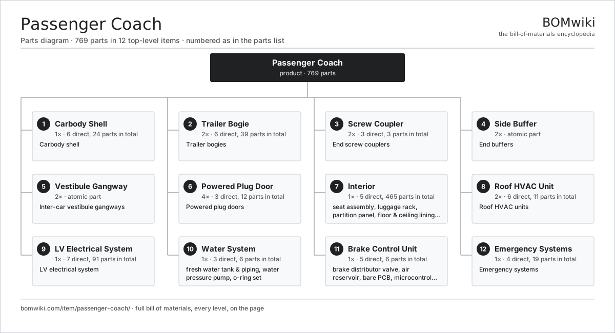
| # | Part | Qty | What it does |
|---|---|---|---|
| 1 | Carbody Shell 6 parts | 1× | Carbody shell |
| 2 | Trailer Bogie 6 parts | 2× | Trailer bogies |
| 3 | Screw Coupler 3 parts | 2× | End screw couplers |
| 4 | Side Buffer | 2× | End buffers |
| 5 | Vestibule Gangway | 2× | Inter-car vestibule gangways |
| 6 | Powered Plug Door 3 parts | 4× | Powered plug doors |
| 7 | Interior 5 parts | 1× | Passenger saloon fit-out: seats, luggage racks, partitions, flooring, ceiling, and a toilet module. |
| 8 | Roof HVAC Unit 6 parts | 2× | Roof HVAC units |
| 9 | LV Electrical System 7 parts | 1× | LV electrical system |
| 10 | Water System 3 parts | 1× | Potable-water supply: storage tank, pressure pump, and distribution piping. |
| 11 | Brake Control Unit 5 parts | 1× | Pneumatic brake control: distributor valve, air reservoir, and electronic controller. |
| 12 | Emergency Systems 4 parts | 1× | Emergency systems |
Diagrams & photos


3D model
No 3D model yet. Have a CAD file of this? Add a 3D model. STL renders right on this page; STEP, FreeCAD, and OpenSCAD sources are welcome too (openly licensed, like all 3D models on BOMwiki).
Build & assembly graph
expand / collapse · shared sub-assemblies converge · links to related products · est. labourTap an assembly to expand/collapse · tap a part to open it · use “Open page” for any node · drag to pan, scroll to zoom.
Bill of materials for Passenger Coach
12 top-level lines · 82 rows shown · 769 parts total · indented to 3 levels| # | Item / sub-assembly | Part no. | Qty/assy | Ext. qty | Parts | Type |
|---|---|---|---|---|---|---|
| 1 | Carbody Shell 6 parts | passenger-coach-carbody | 1× | 1 | 24 | assembly |
| 1.1 | Underframe | passenger-coach-underframe | 1× | 1 | · | part |
| 1.2 | Side Wall Panel | passenger-coach-sidewall | 2× | 2 | · | part |
| 1.3 | Roof Panel | passenger-coach-roof | 1× | 1 | · | part |
| 1.4 | End Wall | passenger-coach-endwall | 2× | 2 | · | part |
| 1.5 | Side Window | passenger-coach-window | 16× | 16 | · | part |
| 1.6 | Fastener Set | fastener-set | 2× | 2 | · | part |
| 2 | Trailer Bogie 6 parts | passenger-coach-bogie | 2× | 2 | 39 | assembly |
| 2.1 | Bogie Frame | passenger-coach-bogie-frame | 1× | 2 | · | part |
| 2.2 | Wheelset 3 parts | passenger-coach-wheelset | 2× | 4 | 5 | assembly |
| 2.2.1 | Axle | passenger-coach-axle | 1× | 4 | · | part |
| 2.2.2 | Monobloc Wheel | passenger-coach-wheel | 2× | 8 | · | part |
| 2.2.3 | Ball Bearing | ball-bearing | 2× | 8 | · | part |
| 2.3 | Coil Spring | coil-spring | 8× | 16 | · | part |
| 2.4 | Air Spring | passenger-coach-air-spring | 2× | 4 | · | part |
| 2.5 | Hydraulic Damper | passenger-coach-damper | 6× | 12 | · | part |
| 2.6 | Disc Brake Unit 3 parts | passenger-coach-disc-brake | 4× | 8 | 3 | assembly |
| 2.6.1 | Wheel-Mounted Brake Disc | passenger-coach-brake-disc | 1× | 8 | · | part |
| 2.6.2 | Brake Caliper & Pads | passenger-coach-brake-caliper | 1× | 8 | · | part |
| 2.6.3 | O-Ring Set | oring-set | 1× | 8 | · | part |
| 3 | Screw Coupler 3 parts | passenger-coach-coupler | 2× | 2 | 3 | assembly |
| 3.1 | Drawhook & Screw Coupling | passenger-coach-drawhook | 1× | 2 | · | part |
| 3.2 | Draft Gear | passenger-coach-draft-gear | 1× | 2 | · | part |
| 3.3 | Fastener Set | fastener-set | 1× | 2 | · | part |
| 4 | Side Buffer | passenger-coach-buffer | 2× | 2 | · | part |
| 5 | Vestibule Gangway | passenger-coach-gangway | 2× | 2 | · | part |
| 6 | Powered Plug Door 3 parts | passenger-coach-door | 4× | 4 | 12 | assembly |
| 6.1 | Door Leaf & Track | passenger-coach-door-leaf | 1× | 4 | · | part |
| 6.2 | Blower Motor | blower-motor | 1× | 4 | · | part |
| 6.3 | Door Control Unit 4 parts | passenger-coach-door-controller | 1× | 4 | 10 | assembly |
| 6.3.1 | Bare PCB | pcb-bare | 1× | 4 | · | part |
| 6.3.2 | Microcontroller | mcu | 1× | 4 | · | part |
| 6.3.3 | Relay | relay | 2× | 8 | · | part |
| 6.3.4 | Connector | connector | 6× | 24 | · | part |
| 7 | Interior 5 parts | passenger-coach-interior | 1× | 1 | 465 | assembly |
| 7.1 | Seat Assembly 5 parts | seat-assembly | 64× | 64 | 7 | assembly |
| 7.1.1 | Seat Frame | seat-frame | 1× | 64 | · | part |
| 7.1.2 | Seat Foam | seat-foam | 2× | 128 | · | part |
| 7.1.3 | Seat Cover | seat-cover | 1× | 64 | · | part |
| 7.1.4 | Seat Motor | seat-motor | 2× | 128 | · | part |
| 7.1.5 | Seat Heater Mat | seat-heater | 1× | 64 | · | part |
| 7.2 | Luggage Rack | passenger-coach-luggage-rack | 8× | 8 | · | part |
| 7.3 | Partition Panel | passenger-coach-partition | 4× | 4 | · | part |
| 7.4 | Floor & Ceiling Lining | passenger-coach-lining | 2× | 2 | · | part |
| 7.5 | Toilet Module 3 parts | passenger-coach-toilet-module | 1× | 1 | 3 | assembly |
| 7.5.1 | Vacuum WC & Basin | passenger-coach-toilet-bowl | 1× | 1 | · | part |
| 7.5.2 | Waste Retention Tank | passenger-coach-retention-tank | 1× | 1 | · | part |
| 7.5.3 | Microcontroller | mcu | 1× | 1 | · | part |
| 8 | Roof HVAC Unit 6 parts | passenger-coach-hvac | 2× | 2 | 11 | assembly |
| 8.1 | Blower Motor | blower-motor | 2× | 4 | · | part |
| 8.2 | HVAC Compressor | passenger-coach-ac-compressor | 1× | 2 | · | part |
| 8.3 | Heating Element | heating-element | 2× | 4 | · | part |
| 8.4 | Bare PCB | pcb-bare | 1× | 2 | · | part |
| 8.5 | Microcontroller | mcu | 1× | 2 | · | part |
| 8.6 | Relay | relay | 4× | 8 | · | part |
| 9 | LV Electrical System 7 parts | passenger-coach-electrical | 1× | 1 | 91 | assembly |
| 9.1 | 12 V Battery | lv-battery | 1× | 1 | · | part |
| 9.2 | LED Light Fixture | passenger-coach-led-fixture | 20× | 20 | · | part |
| 9.3 | Coach Control & PA Board 4 parts | passenger-coach-control-board | 1× | 1 | 31 | assembly |
| 9.3.1 | Bare PCB | pcb-bare | 2× | 2 | · | part |
| 9.3.2 | Microcontroller | mcu | 1× | 1 | · | part |
| 9.3.3 | Relay | relay | 8× | 8 | · | part |
| 9.3.4 | Connector | connector | 20× | 20 | · | part |
| 9.4 | PA Speaker | passenger-coach-speaker | 8× | 8 | · | part |
| 9.5 | LCD Panel | lcd-panel | 6× | 6 | · | part |
| 9.6 | Wire Bundle | wire-bundle | 1× | 1 | · | part |
| 9.7 | Connector | connector | 24× | 24 | · | part |
| 10 | Water System 3 parts | passenger-coach-water-system | 1× | 1 | 6 | assembly |
| 10.1 | Fresh Water Tank & Piping | passenger-coach-water-tank | 1× | 1 | · | part |
| 10.2 | Water Pressure Pump | passenger-coach-water-pump | 1× | 1 | · | part |
| 10.3 | O-Ring Set | oring-set | 4× | 4 | · | part |
| 11 | Brake Control Unit 5 parts | passenger-coach-brake-control | 1× | 1 | 6 | assembly |
| 11.1 | Brake Distributor Valve | passenger-coach-distributor-valve | 1× | 1 | · | part |
| 11.2 | Air Reservoir | passenger-coach-air-reservoir | 1× | 1 | · | part |
| 11.3 | Bare PCB | pcb-bare | 1× | 1 | · | part |
| 11.4 | Microcontroller | mcu | 1× | 1 | · | part |
| 11.5 | Relay | relay | 2× | 2 | · | part |
| 12 | Emergency Systems 4 parts | passenger-coach-emergency | 1× | 1 | 19 | assembly |
| 12.1 | Emergency Brake Handle | passenger-coach-emergency-handle | 4× | 4 | · | part |
| 12.2 | Smoke Detector | passenger-coach-smoke-detector | 6× | 6 | · | part |
| 12.3 | Emergency Light | passenger-coach-emergency-light | 8× | 8 | · | part |
| 12.4 | 12 V Battery | lv-battery | 1× | 1 | · | part |
Something wrong in this list? Report a problem with this BOM.
Related products
same domain, ranked by shared parts Freight Locomotive
1,597 parts · shares 11 with this page
 City Bus
40,967 parts · shares 10 with this page
 Electric Locomotive
2,774 parts · shares 10 with this page
 High-Speed Trainset
1,445,128 parts · shares 10 with this page
 Monorail Car
700 parts · shares 10 with this page
 Double-Decker Bus
864 parts · shares 9 with this page
Sourcing: possible vendors
Browse the supplier directory → Prices, MOQ, and lead times are algorithmic estimates, not quotes, and not claims about these companies. Company mappings are curated by keyword; est. price band $500k–$60M. How estimates work| Vendor | HQ | Specialty | MOQ | Lead time |
|---|---|---|---|---|
|
🇨🇳CRRC
crrcgc.cc ↗
|
Beijing, CN | Rolling stock & rail systems | made to order | 40–72 wks |
|
🇫🇷Alstom
alstom.com ↗
|
Saint-Ouen, FR | Rail rolling stock | made to order | 40–72 wks |
| mobility.siemens.com ↗ | Munich, DE | Rail systems | made to order | 40–72 wks |
| stadlerrail.com ↗ | Bussnang, CH | Rail rolling stock | made to order | 40–72 wks |
|
🇺🇸Wabtec
wabteccorp.com ↗
|
Pittsburgh, US | Rail equipment | made to order | 40–72 wks |
840-word article