Trolleybus
ProductOverview
A trolleybus is a rubber-tyred electric bus that takes its traction power from a pair of overhead wires strung above the street, rather than from an on-board engine or a large battery. Two spring-loaded poles reach up from the roof and slide along the wires, one collecting current and the other returning it, so the vehicle needs no running rail for its earth return the way a tram does. The result is a quiet, locally emission-free bus that keeps the flexibility of road running: it can pull to the kerb, steer around a parked car, and change lanes within the reach of its poles.
The vehicle divides into nine major groups. The Current Collection Gear gear on the roof feeds the Traction System, which turns line power into wheel torque. The Body Shell carries everything and forms the passenger box, while the Running Gear and Braking System handle ride, steering, and stopping. A Low-Voltage System runs the controls and lighting, the HVAC System conditions the saloon, the Passenger Cabin holds the fit-out, and a Auxiliary Power Unit lets the bus run short distances off the wires.
Current collection
Power reaches the bus through the Current Collection Gear gear. Each Trolley Pole is held against its wire by a spring in the Pole Base, which lets the pole rise, fall, and swing sideways as the bus weaves under the line. At the tip a Contact Head guides the wire onto a Carbon Contact Strip, a sacrificial graphite block that takes the wear so the copper wire and the head last. If a pole leaves its wire, a Pole Retriever pulls it down before it can smash the roof or foul the adjacent wire. The live cabling is held off the bonded steel body by Roof Insulators, and a Line Switch isolates the whole traction circuit when the bus is parked or being worked on.
Traction and drive
The Traction System converts the roughly 600 V DC line into the variable three-phase supply a modern AC motor needs. A Line Filter first smooths the current drawn from the wire so the bus does not throw interference back into the network. The Traction Inverter then uses IGBT Modules switching against a stiff DC-Link Capacitor to synthesise a three-phase output, and the Traction Motor turns that into shaft power. The motor is a squirrel-cage machine built from a Stator Assembly and a Rotor Assembly running on Ball Bearings inside a finned Motor Housing. Torque passes through a Helical Gear Pair in the Drive Axle to the rear wheels. When the driver brakes, the inverter runs the motor as a generator and feeds energy back to the wire; if the line cannot take it, the surplus is burned in the roof-mounted Brake Resistor Grid. The whole sequence is commanded by the Traction Controller.
Body, running gear, and brakes
The Body Shell is a welded steel structure: a Underframe carries the axles and battery boxes, two Side Frames and a Roof Frame form the box, and Sheet Metal Panel skins plus glass-fibre Front Mask and Rear Mask caps close it in. The Running Gear gives a low-floor ride: a steered Front Axle turning on Kingpins, Air Springs on every corner held at height by Leveling Valves, and Shock Absorbers to damp the motion. Stopping is shared between regeneration and the Braking System, whose Air Compressor charges the Air Reservoirs that drive Brake Chambers at each Disc Brake. An ABS Modulator prevents lockup and a spring-applied Parking Brake holds the bus when the air is off.
Auxiliaries and cabin
Control power comes from the Low-Voltage System. A DC-DC Converter steps the line down to 24 V, charging Auxiliary Battery units and feeding the Distribution Box that supplies the Light Clusters and the Driver Display. Because the trolleybus has electrical power on tap, its HVAC System heats and cools straight from the line: a Roof AC Unit and Heating Elements feed Cabin Blowers and Air Ducts through the saloon. The Passenger Cabin is fitted with Passenger Seats, Grab Rails, Door Systems, and a Access Ramp for level boarding.
Off-wire operation and variants
The biggest change in modern trolleybuses is the Auxiliary Power Unit. A Traction Battery Pack under the floor, policed by a Battery Management System and switched by HV Contactors, stores enough energy to drive several kilometres with the poles lowered. This lets a route skip the cost of wiring a quiet side street, divert around roadworks, or extend past the end of the overhead. The pack is charged from the wire while the bus runs normally, so it rarely needs depot charging. Trolleybuses are built as rigid two-axle 12 m vehicles and as articulated 18 m units for busy trunk routes, and the same drive train is shared with battery and fuel-cell buses, which is why the inverter, motor, and axle in this list reappear across other electric transit vehicles.
Trolleybus parts and their functions
9 top-level parts · 280 parts in total · full bill of materials below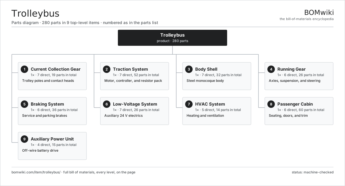
| # | Part | Qty | What it does |
|---|---|---|---|
| 1 | Current Collection Gear 7 parts | 1× | Trolley poles and contact heads |
| 2 | Traction System 7 parts | 1× | Motor, controller, and resistor pack |
| 3 | Body Shell 7 parts | 1× | Steel monocoque body |
| 4 | Running Gear 6 parts | 1× | Axles, suspension, and steering |
| 5 | Braking System 6 parts | 1× | Service and parking brakes |
| 6 | Low-Voltage System 7 parts | 1× | Auxiliary 24 V electrics |
| 7 | HVAC System 5 parts | 1× | Heating and ventilation |
| 8 | Passenger Cabin 6 parts | 1× | Seating, doors, and trim |
| 9 | Auxiliary Power Unit 4 parts | 1× | Off-wire battery drive |
3D model
No 3D model yet. Have a CAD file of this? Add a 3D model. STL renders right on this page; STEP, FreeCAD, and OpenSCAD sources are welcome too (openly licensed, like all 3D models on BOMwiki).
Build & assembly graph
expand / collapse · shared sub-assemblies converge · links to related products · est. labourTap an assembly to expand/collapse · tap a part to open it · use “Open page” for any node · drag to pan, scroll to zoom.
Bill of materials for Trolleybus
9 top-level lines · 103 rows shown · 280 parts total · indented to 3 levels| # | Item / sub-assembly | Part no. | Qty/assy | Ext. qty | Parts | Type |
|---|---|---|---|---|---|---|
| 1 | Current Collection Gear 7 parts | trolleybus-current-collection | 1× | 1 | 19 | assembly |
| 1.1 | Trolley Pole | trolleybus-trolley-pole | 2× | 2 | · | part |
| 1.2 | Contact Head | trolleybus-contact-head | 2× | 2 | · | part |
| 1.3 | Pole Base | trolleybus-pole-base | 2× | 2 | · | part |
| 1.4 | Carbon Contact Strip | trolleybus-carbon-insert | 4× | 4 | · | part |
| 1.5 | Pole Retriever | trolleybus-retriever | 2× | 2 | · | part |
| 1.6 | Roof Insulator | trolleybus-roof-insulator | 6× | 6 | · | part |
| 1.7 | Line Switch | trolleybus-line-switch | 1× | 1 | · | part |
| 2 | Traction System 7 parts | trolleybus-traction-system | 1× | 1 | 52 | assembly |
| 2.1 | Traction Motor 4 parts | trolleybus-traction-motor | 1× | 1 | 25 | assembly |
| 2.1.1 | Stator Assembly 3 parts + deeper › | stator-assembly | 1× | 1 | 3 | assembly |
| 2.1.2 | Rotor Assembly 4 parts + deeper › | rotor-assembly | 1× | 1 | 19 | assembly |
| 2.1.3 | Ball Bearing | ball-bearing | 2× | 2 | · | part |
| 2.1.4 | Motor Housing | trolleybus-motor-housing | 1× | 1 | · | part |
| 2.2 | Traction Inverter 4 parts | trolleybus-traction-inverter | 1× | 1 | 9 | assembly |
| 2.2.1 | IGBT Module | trolleybus-igbt-module | 6× | 6 | · | part |
| 2.2.2 | DC-Link Capacitor | trolleybus-dc-link-cap | 1× | 1 | · | part |
| 2.2.3 | Bare PCB | pcb-bare | 1× | 1 | · | part |
| 2.2.4 | Inverter Heatsink | trolleybus-inverter-heatsink | 1× | 1 | · | part |
| 2.3 | Line Filter | trolleybus-line-filter | 1× | 1 | · | part |
| 2.4 | Brake Resistor Grid | trolleybus-brake-resistor | 1× | 1 | · | part |
| 2.5 | Drive Axle 4 parts | trolleybus-drive-axle | 1× | 1 | 8 | assembly |
| 2.5.1 | Axle Beam | trolleybus-axle-beam | 1× | 1 | · | part |
| 2.5.2 | Gearbox Housing | gearbox-housing | 1× | 1 | · | part |
| 2.5.3 | Ball Bearing | ball-bearing | 4× | 4 | · | part |
| 2.5.4 | Oil Seal | oil-seal | 2× | 2 | · | part |
| 2.6 | Helical Gear Pair | gear-pair | 1× | 1 | · | part |
| 2.7 | Traction Controller 4 parts | trolleybus-traction-controller | 1× | 1 | 7 | assembly |
| 2.7.1 | Microcontroller | mcu | 1× | 1 | · | part |
| 2.7.2 | Bare PCB | pcb-bare | 1× | 1 | · | part |
| 2.7.3 | SMD Passive (R/C/L) | smd-passives | 1× | 1 | · | part |
| 2.7.4 | Connector | connector | 4× | 4 | · | part |
| 3 | Body Shell 7 parts | trolleybus-body-shell | 1× | 1 | 32 | assembly |
| 3.1 | Underframe | trolleybus-underframe | 1× | 1 | · | part |
| 3.2 | Side Frame | trolleybus-side-frame | 2× | 2 | · | part |
| 3.3 | Roof Frame | trolleybus-roof-frame | 1× | 1 | · | part |
| 3.4 | Sheet Metal Panel | sheet-panel | 14× | 14 | · | part |
| 3.5 | Front Mask | trolleybus-front-mask | 1× | 1 | · | part |
| 3.6 | Rear Mask | trolleybus-rear-mask | 1× | 1 | · | part |
| 3.7 | Side Glazing | trolleybus-glazing | 12× | 12 | · | part |
| 4 | Running Gear 6 parts | trolleybus-running-gear | 1× | 1 | 26 | assembly |
| 4.1 | Front Axle 3 parts | trolleybus-front-axle | 1× | 1 | 7 | assembly |
| 4.1.1 | Axle Beam | trolleybus-axle-beam | 1× | 1 | · | part |
| 4.1.2 | Kingpin | trolleybus-kingpin | 2× | 2 | · | part |
| 4.1.3 | Ball Bearing | ball-bearing | 4× | 4 | · | part |
| 4.2 | Air Spring | trolleybus-air-spring | 4× | 4 | · | part |
| 4.3 | Shock Absorber | trolleybus-shock-absorber | 4× | 4 | · | part |
| 4.4 | Steering Gear | trolleybus-steering-gear | 1× | 1 | · | part |
| 4.5 | Wheel and Tyre | trolleybus-wheel | 6× | 6 | · | part |
| 4.6 | Leveling Valve | trolleybus-leveling-valve | 4× | 4 | · | part |
| 5 | Braking System 6 parts | trolleybus-braking-system | 1× | 1 | 36 | assembly |
| 5.1 | Air Compressor | trolleybus-air-compressor | 1× | 1 | · | part |
| 5.2 | Air Reservoir | trolleybus-air-reservoir | 3× | 3 | · | part |
| 5.3 | Brake Chamber | trolleybus-brake-chamber | 6× | 6 | · | part |
| 5.4 | Disc Brake 3 parts | trolleybus-disc-brake | 6× | 6 | 4 | assembly |
| 5.4.1 | Brake Disc | trolleybus-brake-disc | 1× | 6 | · | part |
| 5.4.2 | Brake Pad | trolleybus-brake-pad | 2× | 12 | · | part |
| 5.4.3 | Brake Caliper | trolleybus-caliper | 1× | 6 | · | part |
| 5.5 | ABS Modulator | trolleybus-abs-modulator | 1× | 1 | · | part |
| 5.6 | Parking Brake | trolleybus-parking-brake | 1× | 1 | · | part |
| 6 | Low-Voltage System 7 parts | trolleybus-low-voltage-system | 1× | 1 | 26 | assembly |
| 6.1 | DC-DC Converter 4 parts | trolleybus-dc-dc-converter | 1× | 1 | 5 | assembly |
| 6.1.1 | Bare PCB | pcb-bare | 1× | 1 | · | part |
| 6.1.2 | IGBT Module | trolleybus-igbt-module | 2× | 2 | · | part |
| 6.1.3 | SMD Passive (R/C/L) | smd-passives | 1× | 1 | · | part |
| 6.1.4 | Inverter Heatsink | trolleybus-inverter-heatsink | 1× | 1 | · | part |
| 6.2 | Auxiliary Battery | trolleybus-aux-battery | 2× | 2 | · | part |
| 6.3 | Distribution Box | trolleybus-distribution-box | 1× | 1 | · | part |
| 6.4 | Relay | relay | 8× | 8 | · | part |
| 6.5 | Wire Bundle | wire-bundle | 1× | 1 | · | part |
| 6.6 | Light Cluster | trolleybus-light-cluster | 6× | 6 | · | part |
| 6.7 | Driver Display 3 parts | trolleybus-driver-display | 1× | 1 | 3 | assembly |
| 6.7.1 | LCD Panel | lcd-panel | 1× | 1 | · | part |
| 6.7.2 | Bare PCB | pcb-bare | 1× | 1 | · | part |
| 6.7.3 | Microcontroller | mcu | 1× | 1 | · | part |
| 7 | HVAC System 5 parts | trolleybus-hvac-system | 1× | 1 | 14 | assembly |
| 7.1 | Roof AC Unit 2 parts | trolleybus-roof-ac-unit | 1× | 1 | 3 | assembly |
| 7.1.1 | Cabin Blower | trolleybus-blower | 2× | 2 | · | part |
| 7.1.2 | AC Compressor | trolleybus-ac-compressor | 1× | 1 | · | part |
| 7.2 | Heating Element | heating-element | 4× | 4 | · | part |
| 7.3 | Cabin Blower | trolleybus-blower | 4× | 4 | · | part |
| 7.4 | Air Duct | trolleybus-air-duct | 2× | 2 | · | part |
| 7.5 | Defroster | trolleybus-defroster | 1× | 1 | · | part |
| 8 | Passenger Cabin 6 parts | trolleybus-passenger-cabin | 1× | 1 | 60 | assembly |
| 8.1 | Passenger Seat | trolleybus-passenger-seat | 30× | 30 | · | part |
| 8.2 | Door System 3 parts | trolleybus-door-system | 3× | 3 | 5 | assembly |
| 8.2.1 | Door Leaf | trolleybus-door-leaf | 2× | 6 | · | part |
| 8.2.2 | Door Actuator | trolleybus-door-actuator | 1× | 3 | · | part |
| 8.2.3 | Door Sensor | trolleybus-door-sensor | 2× | 6 | · | part |
| 8.3 | Grab Rail | trolleybus-grab-rail | 12× | 12 | · | part |
| 8.4 | Floor Covering | trolleybus-floor-covering | 1× | 1 | · | part |
| 8.5 | Driver Seat | trolleybus-driver-seat | 1× | 1 | · | part |
| 8.6 | Access Ramp | trolleybus-ramp | 1× | 1 | · | part |
| 9 | Auxiliary Power Unit 4 parts | trolleybus-aux-power-unit | 1× | 1 | 15 | assembly |
| 9.1 | Traction Battery Pack 2 parts | trolleybus-battery-pack | 1× | 1 | 9 | assembly |
| 9.1.1 | Battery Module | trolleybus-battery-module | 8× | 8 | · | part |
| 9.1.2 | Battery Enclosure | trolleybus-battery-enclosure | 1× | 1 | · | part |
| 9.2 | Battery Management System 3 parts | trolleybus-battery-bms | 1× | 1 | 3 | assembly |
| 9.2.1 | Microcontroller | mcu | 1× | 1 | · | part |
| 9.2.2 | Bare PCB | pcb-bare | 1× | 1 | · | part |
| 9.2.3 | SMD Passive (R/C/L) | smd-passives | 1× | 1 | · | part |
| 9.3 | HV Contactor | trolleybus-battery-contactor | 2× | 2 | · | part |
| 9.4 | Battery Cooling Loop | trolleybus-battery-cooling | 1× | 1 | · | part |
Related products
same domain, ranked by shared parts Automated People Mover
450 parts · shares 14 with this page
Automated People Mover
450 parts · shares 14 with this page
 Bus Rapid Transit Vehicle
4,251 parts · shares 14 with this page
Bus Rapid Transit Vehicle
4,251 parts · shares 14 with this page
 Commuter EMU
14,010 parts · shares 14 with this page
Commuter EMU
14,010 parts · shares 14 with this page
 Diesel Multiple Unit
12,609 parts · shares 14 with this page
Diesel Multiple Unit
12,609 parts · shares 14 with this page
 Electric Bus
4,481 parts · shares 14 with this page
Electric Bus
4,481 parts · shares 14 with this page
 Minibus
1,878 parts · shares 14 with this page
Minibus
1,878 parts · shares 14 with this page
Sourcing: possible vendors
Browse the supplier directory → Prices, MOQ, and lead times are algorithmic estimates, not quotes, and not claims about these companies. Company mappings are curated by keyword; est. price band $500k–$60M. How estimates work| Vendor | HQ | Specialty | MOQ | Lead time |
|---|---|---|---|---|
|
🇨🇳CRRC
crrcgc.cc ↗
|
Beijing, CN | Rolling stock & rail systems | made to order | 40–72 wks |
|
🇫🇷Alstom
alstom.com ↗
|
Saint-Ouen, FR | Rail rolling stock | made to order | 40–72 wks |
| mobility.siemens.com ↗ | Munich, DE | Rail systems | made to order | 40–72 wks |
| stadlerrail.com ↗ | Bussnang, CH | Rail rolling stock | made to order | 40–72 wks |
|
🇺🇸Wabtec
wabteccorp.com ↗
|
Pittsburgh, US | Rail equipment | made to order | 40–72 wks |
906-word article