Rail Inspection Trolley
ProductOverview
A rail inspection trolley is a small self-propelled vehicle that carries a crew and survey equipment along the track to check rail condition and geometry. It fills the gap between hand walking, which is slow, and a full inspection train, which is expensive and needs a possession of the line. A typical trolley weighs between 350 and 900 kg, seats one or two people, and runs at up to 40 km/h while surveying and 60 km/h in transit between sites. It runs on four flanged steel wheels on standard 1435 mm gauge, with 1000 mm and 1676 mm versions for narrow and broad gauge networks.
The vehicle is light enough that two people can lift one end with the Rerailing Jack and turn it off the rail to clear an approaching train. That property defines much of the design: every subsystem is sized to keep total weight low while still carrying useful inspection sensors.
Drive and transmission
Two drive layouts are common. The diesel variant uses a small water-cooled Diesel Engine of 12 to 25 kW driving through a Clutch and a Gearbox. The gearbox output turns a Drive Chain running to a sprocket on one Axle. The battery-electric variant replaces the engine with a Traction Motor, a brushless DC unit fed by a controller, which removes engine noise and exhaust and suits tunnel and depot work. A Battery of 8 to 15 kWh at 48 or 80 V gives a working shift of survey running between charges.
Both variants drive a single axle. The wheels are forged steel with a profiled flange that follows the rail head, and they ride in Axle Box housings on tapered roller Ball Bearing sets. Suspension is by Leaf Spring or coil spring, which keeps the sensor mounts steady enough for repeatable geometry readings.
Measurement systems
The survey payload is the reason the trolley exists. Ultrasonic flaw detection uses an array of Ultrasonic Probe transducers held against the rail by a sprung Probe Carriage. Probes operate at 2 to 5 MHz, with angled beams to find transverse cracks in the rail head and normal beams to check the web and foot. A Couplant Tank sprays water ahead of the probes so the sound energy crosses into the steel instead of reflecting off the air gap.
Track geometry is measured by the Track Geometry Sensor, which combines a laser profile head with an inertial unit to record gauge, cant, twist, alignment, and longitudinal level against EN 13848 limits. Every reading is tagged for location by the GPS Receiver and refined by a wheel Wheel Odometer so that a flaw can be found again to within a metre. The Data Recorder logs all channels with a common time base, and forward Inspection Camera units record the rail surface and fastenings for later review.
Braking and safety
The trolley carries a hydraulic disc service brake. A Brake Pedal feeds the Master Cylinder, which pressurises four Brake Caliper units clamping a disc on each wheel. A pressure sensor on the line warns of any loss of pressure. A separate ratchet Parking Brake locks the wheels when the trolley is stabled. Because trolleys often work under traffic, the Warning Beacon and horn warn track workers and signal staff of the vehicle, and the design allows a fast manual turn-off using the rerailing jack.
Materials and construction
The Main Frame is a welded box-section steel structure that carries the running gear, drive, and payload. Wheels and axles are forged steel for fatigue strength. Panels and the operator canopy use sheet steel or aluminium to keep weight down. The electrical system runs from the battery through a fuse box and a DC-DC Power Supply that feeds the control board and sensor electronics, with a single isolator switch for safe parking.
Variants
Diesel trolleys suit open lines with long distances between charging. Battery-electric trolleys suit tunnels, stations, and depots where exhaust is a problem. A lighter inspection-only build drops the Lifting and Track-Clearing System system and the clearing blade to reduce weight for crews who only record data. A maintenance build adds the Clearing Blade and a powered jack so the same vehicle can clear debris and do small repairs.
Use and operations
A two-person crew drives the trolley onto the track at a level crossing or access point, sets the survey speed between 5 and 20 km/h, and runs the section while the recorder logs every metre. Flaws and geometry faults are flagged in real time on the cab display and reviewed in the office against the recorded position. When a train is due, the crew brakes, lifts the trolley with the jack, and turns it clear of the rail, then returns it once the line is free.
Rail Inspection Trolley parts and their functions
8 top-level parts · 251 parts in total · full bill of materials below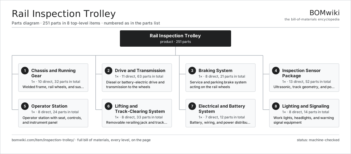
| # | Part | Qty | What it does |
|---|---|---|---|
| 1 | Chassis and Running Gear 10 parts | 1× | Welded frame, rail wheels, and suspension carrying the whole vehicle |
| 2 | Drive and Transmission 11 parts | 1× | Diesel or battery-electric drive and transmission to the wheels |
| 3 | Braking System 8 parts | 1× | Service and parking brake system acting on the rail wheels |
| 4 | Inspection Sensor Package 13 parts | 1× | Ultrasonic, track geometry, and positioning sensor package |
| 5 | Operator Station 8 parts | 1× | Operator station with seat, controls, and instrument panel |
| 6 | Lifting and Track-Clearing System 8 parts | 1× | Removable rerailing jack and track-clearing equipment |
| 7 | Electrical and Battery System 7 parts | 1× | Battery, wiring, and power distribution for the vehicle |
| 8 | Lighting and Signaling 8 parts | 1× | Work lights, headlights, and warning signal equipment |
3D model
No 3D model yet. Have a CAD file of this? Add a 3D model. STL renders right on this page; STEP, FreeCAD, and OpenSCAD sources are welcome too (openly licensed, like all 3D models on BOMwiki).
Build & assembly graph
expand / collapse · shared sub-assemblies converge · links to related products · est. labourTap an assembly to expand/collapse · tap a part to open it · use “Open page” for any node · drag to pan, scroll to zoom.
Bill of materials for Rail Inspection Trolley
8 top-level lines · 117 rows shown · 251 parts total · indented to 3 levels| # | Item / sub-assembly | Part no. | Qty/assy | Ext. qty | Parts | Type |
|---|---|---|---|---|---|---|
| 1 | Chassis and Running Gear 10 parts | inspection-trolley-chassis | 1× | 1 | 32 | assembly |
| 1.1 | Main Frame | inspection-trolley-main-frame | 1× | 1 | · | part |
| 1.2 | Rail Wheel | inspection-trolley-rail-wheel | 4× | 4 | · | part |
| 1.3 | Axle | inspection-trolley-axle | 2× | 2 | · | part |
| 1.4 | Axle Box | inspection-trolley-axle-box | 4× | 4 | · | part |
| 1.5 | Ball Bearing | ball-bearing | 8× | 8 | · | part |
| 1.6 | Leaf Spring | inspection-trolley-leaf-spring | 4× | 4 | · | part |
| 1.7 | Coil Spring | coil-spring | 4× | 4 | · | part |
| 1.8 | End Buffer | inspection-trolley-buffer | 2× | 2 | · | part |
| 1.9 | Coupler | inspection-trolley-coupler | 2× | 2 | · | part |
| 1.10 | Fastener Set | fastener-set | 1× | 1 | · | part |
| 2 | Drive and Transmission 11 parts | inspection-trolley-drive | 1× | 1 | 63 | assembly |
| 2.1 | Diesel Engine 10 parts | inspection-trolley-engine | 1× | 1 | 11 | assembly |
| 2.1.1 | Engine Block | inspection-trolley-engine-block | 1× | 1 | · | part |
| 2.1.2 | Piston Set | inspection-trolley-piston-set | 1× | 1 | · | part |
| 2.1.3 | Crankshaft | inspection-trolley-crankshaft | 1× | 1 | · | part |
| 2.1.4 | Cylinder Head | inspection-trolley-cylinder-head | 1× | 1 | · | part |
| 2.1.5 | Fuel Injection Pump | inspection-trolley-fuel-pump | 1× | 1 | · | part |
| 2.1.6 | Radiator | inspection-trolley-radiator | 1× | 1 | · | part |
| 2.1.7 | Starter Motor | inspection-trolley-starter-motor | 1× | 1 | · | part |
| 2.1.8 | Alternator | inspection-trolley-alternator | 1× | 1 | · | part |
| 2.1.9 | Air Filter | inspection-trolley-air-filter | 1× | 1 | · | part |
| 2.1.10 | Ball Bearing | ball-bearing | 2× | 2 | · | part |
| 2.2 | Traction Motor 6 parts | inspection-trolley-traction-motor | 1× | 1 | 29 | assembly |
| 2.2.1 | Stator Assembly 3 parts + deeper › | stator-assembly | 1× | 1 | 3 | assembly |
| 2.2.2 | Rotor Assembly 4 parts + deeper › | rotor-assembly | 1× | 1 | 19 | assembly |
| 2.2.3 | Motor Controller | inspection-trolley-motor-controller | 1× | 1 | · | part |
| 2.2.4 | Ball Bearing | ball-bearing | 2× | 2 | · | part |
| 2.2.5 | Oil Seal | oil-seal | 1× | 1 | · | part |
| 2.2.6 | Connector | connector | 3× | 3 | · | part |
| 2.3 | Clutch | inspection-trolley-clutch | 1× | 1 | · | part |
| 2.4 | Gearbox 5 parts | inspection-trolley-gearbox | 1× | 1 | 11 | assembly |
| 2.4.1 | Helical Gear Pair | gear-pair | 3× | 3 | · | part |
| 2.4.2 | Gearbox Housing | gearbox-housing | 1× | 1 | · | part |
| 2.4.3 | Shift Lever | inspection-trolley-shift-lever | 1× | 1 | · | part |
| 2.4.4 | Ball Bearing | ball-bearing | 4× | 4 | · | part |
| 2.4.5 | Oil Seal | oil-seal | 2× | 2 | · | part |
| 2.5 | Helical Gear Pair | gear-pair | 1× | 1 | · | part |
| 2.6 | Gearbox Housing | gearbox-housing | 1× | 1 | · | part |
| 2.7 | Drive Chain | inspection-trolley-drive-chain | 1× | 1 | · | part |
| 2.8 | Drive Sprocket | inspection-trolley-drive-sprocket | 2× | 2 | · | part |
| 2.9 | Drive Belt | drive-belt | 1× | 1 | · | part |
| 2.10 | Fuel Tank | inspection-trolley-fuel-tank | 1× | 1 | · | part |
| 2.11 | Oil Seal | oil-seal | 4× | 4 | · | part |
| 3 | Braking System 8 parts | inspection-trolley-brakes | 1× | 1 | 21 | assembly |
| 3.1 | Brake Disc | inspection-trolley-brake-disc | 4× | 4 | · | part |
| 3.2 | Brake Caliper | inspection-trolley-brake-caliper | 4× | 4 | · | part |
| 3.3 | Brake Pad | inspection-trolley-brake-pad | 8× | 8 | · | part |
| 3.4 | Master Cylinder | inspection-trolley-master-cylinder | 1× | 1 | · | part |
| 3.5 | Brake Line | inspection-trolley-brake-line | 1× | 1 | · | part |
| 3.6 | Parking Brake | inspection-trolley-parking-brake | 1× | 1 | · | part |
| 3.7 | Brake Pedal | inspection-trolley-brake-pedal | 1× | 1 | · | part |
| 3.8 | Pressure Sensor | pressure-sensor | 1× | 1 | · | part |
| 4 | Inspection Sensor Package 13 parts | inspection-trolley-inspection | 1× | 1 | 52 | assembly |
| 4.1 | Ultrasonic Probe | inspection-trolley-ultrasonic-probe | 6× | 6 | · | part |
| 4.2 | Probe Carriage | inspection-trolley-probe-carriage | 2× | 2 | · | part |
| 4.3 | Couplant Tank | inspection-trolley-couplant-tank | 1× | 1 | · | part |
| 4.4 | Track Geometry Sensor 6 parts | inspection-trolley-geometry-sensor | 4× | 4 | 7 | assembly |
| 4.4.1 | Laser Profile Head | inspection-trolley-laser-head | 1× | 4 | · | part |
| 4.4.2 | Inertial Measurement Unit | inspection-trolley-imu | 1× | 4 | · | part |
| 4.4.3 | Bare PCB | pcb-bare | 1× | 4 | · | part |
| 4.4.4 | Microcontroller | mcu | 1× | 4 | · | part |
| 4.4.5 | SMD Passive (R/C/L) | smd-passives | 1× | 4 | · | part |
| 4.4.6 | Connector | connector | 2× | 8 | · | part |
| 4.5 | GPS Receiver | inspection-trolley-gps-receiver | 1× | 1 | · | part |
| 4.6 | Wheel Odometer | inspection-trolley-odometer | 1× | 1 | · | part |
| 4.7 | Data Recorder | inspection-trolley-data-recorder | 1× | 1 | · | part |
| 4.8 | Inspection Camera | inspection-trolley-camera | 2× | 2 | · | part |
| 4.9 | Bare PCB | pcb-bare | 1× | 1 | · | part |
| 4.10 | Microcontroller | mcu | 1× | 1 | · | part |
| 4.11 | SMD Passive (R/C/L) | smd-passives | 1× | 1 | · | part |
| 4.12 | Connector | connector | 6× | 6 | · | part |
| 4.13 | Wire Bundle | wire-bundle | 1× | 1 | · | part |
| 5 | Operator Station 8 parts | inspection-trolley-cab | 1× | 1 | 24 | assembly |
| 5.1 | Operator Seat | inspection-trolley-seat | 2× | 2 | · | part |
| 5.2 | Throttle Lever | inspection-trolley-throttle | 1× | 1 | · | part |
| 5.3 | Dash Panel | inspection-trolley-dash-panel | 1× | 1 | · | part |
| 5.4 | LCD Panel | lcd-panel | 1× | 1 | · | part |
| 5.5 | Vehicle Control Board 5 parts | inspection-trolley-control-board | 1× | 1 | 10 | assembly |
| 5.5.1 | Bare PCB | pcb-bare | 1× | 1 | · | part |
| 5.5.2 | Microcontroller | mcu | 1× | 1 | · | part |
| 5.5.3 | SMD Passive (R/C/L) | smd-passives | 1× | 1 | · | part |
| 5.5.4 | Relay | relay | 2× | 2 | · | part |
| 5.5.5 | Connector | connector | 5× | 5 | · | part |
| 5.6 | Relay | relay | 4× | 4 | · | part |
| 5.7 | Weather Canopy | inspection-trolley-canopy | 1× | 1 | · | part |
| 5.8 | Connector | connector | 4× | 4 | · | part |
| 6 | Lifting and Track-Clearing System 8 parts | inspection-trolley-lifting | 1× | 1 | 33 | assembly |
| 6.1 | Rerailing Jack | inspection-trolley-rerail-jack | 1× | 1 | · | part |
| 6.2 | Jack Pump | inspection-trolley-jack-pump | 1× | 1 | · | part |
| 6.3 | Clearing Blade | inspection-trolley-clearing-blade | 1× | 1 | · | part |
| 6.4 | Lift Arm | inspection-trolley-lift-arm | 2× | 2 | · | part |
| 6.5 | Ball Screw | ball-screw | 1× | 1 | · | part |
| 6.6 | Linear Guide Rail | linear-guide | 2× | 2 | · | part |
| 6.7 | Servo Motor 4 parts | servo-motor | 1× | 1 | 24 | assembly |
| 6.7.1 | Stator Assembly 3 parts + deeper › | stator-assembly | 1× | 1 | 3 | assembly |
| 6.7.2 | Rotor Assembly 4 parts + deeper › | rotor-assembly | 1× | 1 | 19 | assembly |
| 6.7.3 | Encoder | encoder | 1× | 1 | · | part |
| 6.7.4 | Motor Housing | motor-housing | 1× | 1 | · | part |
| 6.8 | Fastener Set | fastener-set | 1× | 1 | · | part |
| 7 | Electrical and Battery System 7 parts | inspection-trolley-electrical | 1× | 1 | 12 | assembly |
| 7.1 | Battery | inspection-trolley-battery | 1× | 1 | · | part |
| 7.2 | Fuse Box | inspection-trolley-fuse-box | 1× | 1 | · | part |
| 7.3 | On-board Charger | inspection-trolley-charger | 1× | 1 | · | part |
| 7.4 | Power Supply | power-supply | 1× | 1 | · | part |
| 7.5 | Battery Isolator | inspection-trolley-isolator-switch | 1× | 1 | · | part |
| 7.6 | Wire Bundle | wire-bundle | 1× | 1 | · | part |
| 7.7 | Connector | connector | 6× | 6 | · | part |
| 8 | Lighting and Signaling 8 parts | inspection-trolley-lighting | 1× | 1 | 14 | assembly |
| 8.1 | Headlight | inspection-trolley-headlight | 2× | 2 | · | part |
| 8.2 | Work Light | inspection-trolley-work-light | 4× | 4 | · | part |
| 8.3 | Warning Beacon | inspection-trolley-beacon | 1× | 1 | · | part |
| 8.4 | Horn | inspection-trolley-horn | 1× | 1 | · | part |
| 8.5 | Tail Light | inspection-trolley-tail-light | 2× | 2 | · | part |
| 8.6 | Heating Element | heating-element | 1× | 1 | · | part |
| 8.7 | Relay | relay | 2× | 2 | · | part |
| 8.8 | Wire Bundle | wire-bundle | 1× | 1 | · | part |
Related products
same domain, ranked by shared parts Automated People Mover
450 parts · shares 21 with this page
Automated People Mover
450 parts · shares 21 with this page
 Bus Rapid Transit Vehicle
4,251 parts · shares 21 with this page
Bus Rapid Transit Vehicle
4,251 parts · shares 21 with this page
 Overhead Wire Maintenance Car
230 parts · shares 21 with this page
Overhead Wire Maintenance Car
230 parts · shares 21 with this page
 Rubber-Tyred Metro Car
3,067 parts · shares 21 with this page
Rubber-Tyred Metro Car
3,067 parts · shares 21 with this page
 Electric Bus
4,481 parts · shares 20 with this page
Electric Bus
4,481 parts · shares 20 with this page
 Party Bus
696 parts · shares 20 with this page
Party Bus
696 parts · shares 20 with this page
Sourcing: possible vendors
Browse the supplier directory → Prices, MOQ, and lead times are algorithmic estimates, not quotes, and not claims about these companies. Company mappings are curated by keyword; est. price band $500k–$60M. How estimates work| Vendor | HQ | Specialty | MOQ | Lead time |
|---|---|---|---|---|
|
🇨🇳CRRC
crrcgc.cc ↗
|
Beijing, CN | Rolling stock & rail systems | made to order | 40–72 wks |
|
🇫🇷Alstom
alstom.com ↗
|
Saint-Ouen, FR | Rail rolling stock | made to order | 40–72 wks |
| mobility.siemens.com ↗ | Munich, DE | Rail systems | made to order | 40–72 wks |
| stadlerrail.com ↗ | Bussnang, CH | Rail rolling stock | made to order | 40–72 wks |
|
🇺🇸Wabtec
wabteccorp.com ↗
|
Pittsburgh, US | Rail equipment | made to order | 40–72 wks |
844-word article