Electric Locomotive
ProductOverview
An electric locomotive draws power from an overhead line and uses it to drive traction motors, with no onboard fuel or prime mover. This mainline machine takes 25 kV AC through a roof pantograph, steps it down in a main transformer, and feeds IGBT converters that drive four traction motors. The major systems are the Underframe and Carbody structures, the Pantograph and HV Roof Equipment power intake, the Main Transformer, two Traction Converter units, an Auxiliary Converter, two Bogie running gears, the Air Brake System, the Train Control System control, and the Cab Equipment. Two 12 V Battery units, four Sander Unit adhesion units, and four Headlight lamps complete it.
Structure
The Underframe is a welded Underframe Weldment that carries body and traction loads, fitted with two Automatic Coupler knuckle couplers and four Side Buffer side buffers. The Carbody is a self-supporting Body Shell with two Cab Shell driving cabs at each end.
Power intake
The Pantograph is a single-arm collector whose two Carbon Contact Strip carbon strips ride the contact wire; an Pantograph Arm raises and lowers it from a set of Base Insulator standoffs. From there current passes through the HV Roof Equipment equipment: an Vacuum Circuit Breaker vacuum breaker that can isolate the loco from the catenary, an Surge Arrester clamping voltage spikes, an HV Roof Busbar busbar, and six HV Roof Insulator supports.
Transformer and converters
The Main Transformer steps 25 kV down to converter-feed voltages. A laminated Transformer Core carries six Copper Winding windings in an oil-filled Transformer Tank, cooled by two Oil Radiator coolers and two Blower Motor fans. Each Traction Converter is a liquid-cooled cabinet: twenty IGBT Power Module switches with ten Gate Driver Board drivers rectify the transformer feed to a DC link held by six DC-Link Capacitor capacitors, then invert it to variable-frequency three-phase for the motors, all in an Converter Cabinet. The Auxiliary Converter supplies the three-phase auxiliaries and charges the battery.
Bogies and running gear
Each Bogie is a welded Bogie Frame carrying two Traction Motor motors, two Gear Unit final drives, two Wheelset wheelsets, six Suspension Spring springs, and two Disc Brake Unit disc brakes. Each Traction Motor is a three-phase asynchronous machine with a Stator Assembly and Rotor Assembly on Ball Bearing supports. A Wheelset presses two Monobloc Wheel monobloc wheels onto a shared Axle, and the Disc Brake Unit clamps a Brake Disc with a Brake Caliper.
Brakes and control
The Air Brake System is pneumatic. An Air Compressor charges two Air Reservoir tanks, and two Brake Control Valve valves distribute air to the brake cylinders. The Train Control System ties the locomotive together: an Loco Computer central unit, two LCD Panel driver displays, an ETCS Onboard Unit signaling computer, and a Wire Bundle of control cabling with sixty Connector points and twenty-four Relay units.
Cab and adhesion
The Cab Equipment fits out each cab with two Seat Assembly seats, a Master Controller throttle and brake handle, an LCD Panel desk display, and a Cab HVAC Unit climate unit. To keep the wheels gripping in poor conditions, four Sander Unit units drop sand at the wheel-rail contact, and the Headlight lamps light the line ahead at both ends.
Electric Locomotive parts and their functions
14 top-level parts · 2,774 parts in total · full bill of materials below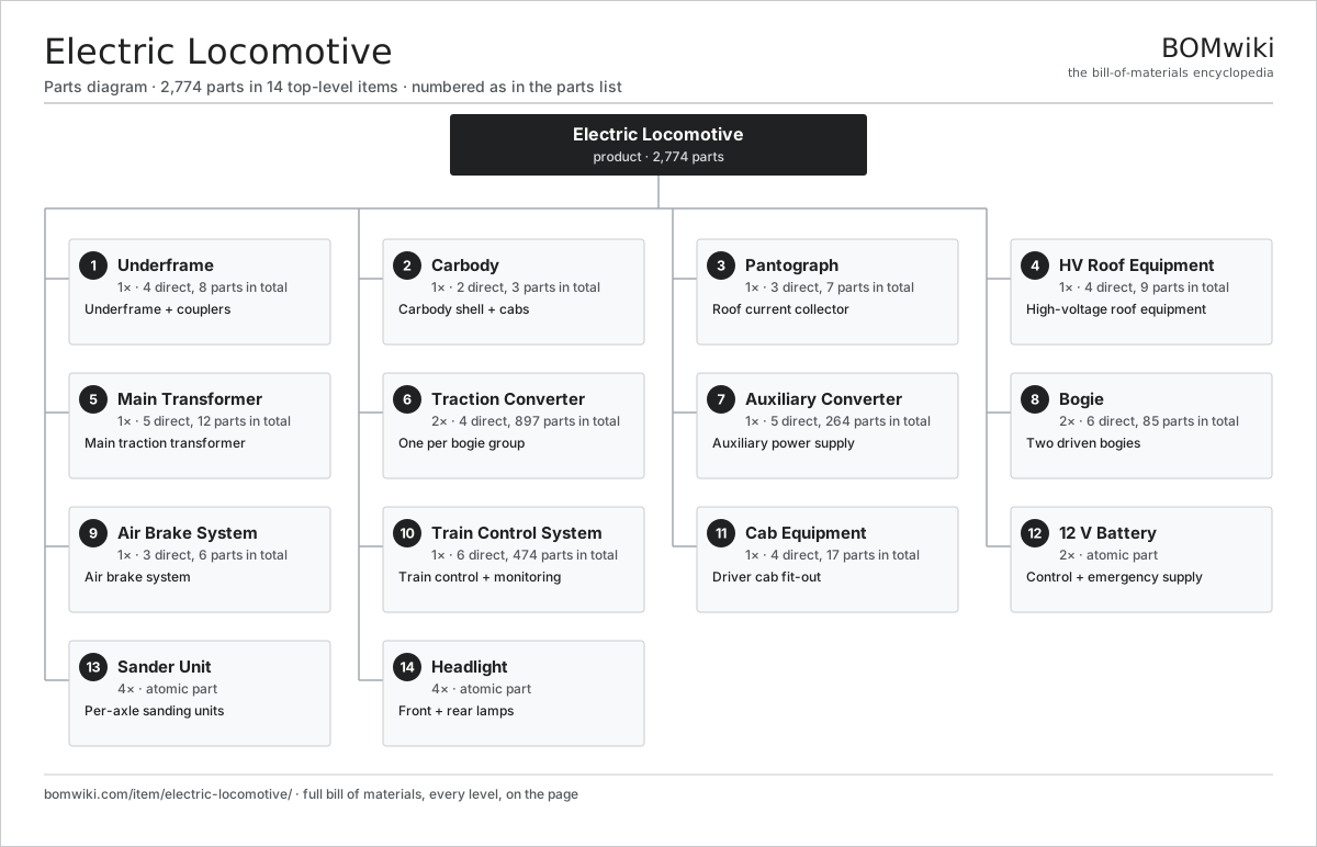
| # | Part | Qty | What it does |
|---|---|---|---|
| 1 | Underframe 4 parts | 1× | Underframe + couplers |
| 2 | Carbody 2 parts | 1× | Carbody shell + cabs |
| 3 | Pantograph 3 parts | 1× | Roof current collector |
| 4 | HV Roof Equipment 4 parts | 1× | High-voltage roof equipment |
| 5 | Main Transformer 5 parts | 1× | Main traction transformer |
| 6 | Traction Converter 4 parts | 2× | One per bogie group |
| 7 | Auxiliary Converter 5 parts | 1× | Auxiliary power supply |
| 8 | Bogie 6 parts | 2× | Two driven bogies |
| 9 | Air Brake System 3 parts | 1× | Air brake system |
| 10 | Train Control System 6 parts | 1× | Train control + monitoring |
| 11 | Cab Equipment 4 parts | 1× | Driver cab fit-out |
| 12 | 12 V Battery | 2× | Control + emergency supply |
| 13 | Sander Unit | 4× | Per-axle sanding units |
| 14 | Headlight | 4× | Front + rear lamps |
Diagrams & photos


3D model
No 3D model yet. Have a CAD file of this? Add a 3D model. STL renders right on this page; STEP, FreeCAD, and OpenSCAD sources are welcome too (openly licensed, like all 3D models on BOMwiki).
Build & assembly graph
expand / collapse · shared sub-assemblies converge · links to related products · est. labourTap an assembly to expand/collapse · tap a part to open it · use “Open page” for any node · drag to pan, scroll to zoom.
Bill of materials for Electric Locomotive
14 top-level lines · 92 rows shown · 2,774 parts total · indented to 3 levels| # | Item / sub-assembly | Part no. | Qty/assy | Ext. qty | Parts | Type |
|---|---|---|---|---|---|---|
| 1 | Underframe 4 parts | electric-locomotive-mainframe | 1× | 1 | 8 | assembly |
| 1.1 | Underframe Weldment | electric-locomotive-underframe-weldment | 1× | 1 | · | part |
| 1.2 | Automatic Coupler | electric-locomotive-coupler | 2× | 2 | · | part |
| 1.3 | Side Buffer | electric-locomotive-buffer | 4× | 4 | · | part |
| 1.4 | Fastener Set | fastener-set | 1× | 1 | · | part |
| 2 | Carbody 2 parts | electric-locomotive-carbody | 1× | 1 | 3 | assembly |
| 2.1 | Body Shell | electric-locomotive-body-shell | 1× | 1 | · | part |
| 2.2 | Cab Shell | electric-locomotive-cab-shell | 2× | 2 | · | part |
| 3 | Pantograph 3 parts | electric-locomotive-pantograph | 1× | 1 | 7 | assembly |
| 3.1 | Carbon Contact Strip | electric-locomotive-contact-strip | 2× | 2 | · | part |
| 3.2 | Pantograph Arm | electric-locomotive-pan-arm | 1× | 1 | · | part |
| 3.3 | Base Insulator | electric-locomotive-base-insulator | 4× | 4 | · | part |
| 4 | HV Roof Equipment 4 parts | electric-locomotive-hv-roof | 1× | 1 | 9 | assembly |
| 4.1 | Vacuum Circuit Breaker | electric-locomotive-vcb | 1× | 1 | · | part |
| 4.2 | Surge Arrester | electric-locomotive-surge-arrester | 1× | 1 | · | part |
| 4.3 | HV Roof Busbar | electric-locomotive-roof-bus | 1× | 1 | · | part |
| 4.4 | HV Roof Insulator | electric-locomotive-hv-insulator | 6× | 6 | · | part |
| 5 | Main Transformer 5 parts | electric-locomotive-transformer | 1× | 1 | 12 | assembly |
| 5.1 | Transformer Core | electric-locomotive-transformer-core | 1× | 1 | · | part |
| 5.2 | Copper Winding | copper-winding | 6× | 6 | · | part |
| 5.3 | Transformer Tank | electric-locomotive-transformer-tank | 1× | 1 | · | part |
| 5.4 | Oil Radiator | electric-locomotive-oil-radiator | 2× | 2 | · | part |
| 5.5 | Blower Motor | blower-motor | 2× | 2 | · | part |
| 6 | Traction Converter 4 parts | electric-locomotive-traction-converter | 2× | 2 | 897 | assembly |
| 6.1 | IGBT Power Module | igbt-module | 20× | 40 | · | part |
| 6.2 | Gate Driver Board 3 parts | gate-driver-board | 10× | 20 | 87 | assembly |
| 6.2.1 | Bare PCB | pcb-bare | 1× | 20 | · | part |
| 6.2.2 | Gate Driver IC | gate-driver-ic | 6× | 120 | · | part |
| 6.2.3 | SMD Passive (R/C/L) | smd-passives | 80× | 1,600 | · | part |
| 6.3 | DC-Link Capacitor | dc-link-cap | 6× | 12 | · | part |
| 6.4 | Converter Cabinet | electric-locomotive-converter-cabinet | 1× | 2 | · | part |
| 7 | Auxiliary Converter 5 parts | electric-locomotive-aux-converter | 1× | 1 | 264 | assembly |
| 7.1 | IGBT Power Module | igbt-module | 6× | 6 | · | part |
| 7.2 | Gate Driver Board 3 parts | gate-driver-board | 2× | 2 | 87 | assembly |
| 7.2.1 | Bare PCB | pcb-bare | 1× | 2 | · | part |
| 7.2.2 | Gate Driver IC | gate-driver-ic | 6× | 12 | · | part |
| 7.2.3 | SMD Passive (R/C/L) | smd-passives | 80× | 160 | · | part |
| 7.3 | DC-Link Capacitor | dc-link-cap | 3× | 3 | · | part |
| 7.4 | Bare PCB | pcb-bare | 1× | 1 | · | part |
| 7.5 | SMD Passive (R/C/L) | smd-passives | 80× | 80 | · | part |
| 8 | Bogie 6 parts | electric-locomotive-bogie | 2× | 2 | 85 | assembly |
| 8.1 | Bogie Frame | electric-locomotive-bogie-frame | 1× | 2 | · | part |
| 8.2 | Traction Motor 3 parts | electric-locomotive-traction-motor | 2× | 4 | 24 | assembly |
| 8.2.1 | Stator Assembly 3 parts + deeper › | stator-assembly | 1× | 4 | 3 | assembly |
| 8.2.2 | Rotor Assembly 4 parts + deeper › | rotor-assembly | 1× | 4 | 19 | assembly |
| 8.2.3 | Ball Bearing | ball-bearing | 2× | 8 | · | part |
| 8.3 | Gear Unit 3 parts | electric-locomotive-gear-unit | 2× | 4 | 7 | assembly |
| 8.3.1 | Helical Gear Pair | gear-pair | 1× | 4 | · | part |
| 8.3.2 | Ball Bearing | ball-bearing | 4× | 16 | · | part |
| 8.3.3 | Oil Seal | oil-seal | 2× | 8 | · | part |
| 8.4 | Wheelset 3 parts | electric-locomotive-wheelset | 2× | 4 | 5 | assembly |
| 8.4.1 | Axle | electric-locomotive-axle | 1× | 4 | · | part |
| 8.4.2 | Monobloc Wheel | electric-locomotive-wheel | 2× | 8 | · | part |
| 8.4.3 | Ball Bearing | ball-bearing | 2× | 8 | · | part |
| 8.5 | Suspension Spring | electric-locomotive-suspension-spring | 6× | 12 | · | part |
| 8.6 | Disc Brake Unit 3 parts | electric-locomotive-brake-unit | 2× | 4 | 3 | assembly |
| 8.6.1 | Brake Disc | electric-locomotive-brake-disc | 1× | 4 | · | part |
| 8.6.2 | Brake Caliper | electric-locomotive-brake-caliper | 1× | 4 | · | part |
| 8.6.3 | O-Ring Set | oring-set | 1× | 4 | · | part |
| 9 | Air Brake System 3 parts | electric-locomotive-brake-system | 1× | 1 | 6 | assembly |
| 9.1 | Air Compressor 2 parts | electric-locomotive-air-compressor | 1× | 1 | 2 | assembly |
| 9.1.1 | Blower Motor | blower-motor | 1× | 1 | · | part |
| 9.1.2 | O-Ring Set | oring-set | 1× | 1 | · | part |
| 9.2 | Air Reservoir | electric-locomotive-air-reservoir | 2× | 2 | · | part |
| 9.3 | Brake Control Valve | electric-locomotive-brake-valve | 2× | 2 | · | part |
| 10 | Train Control System 6 parts | electric-locomotive-tcms | 1× | 1 | 474 | assembly |
| 10.1 | Loco Computer 4 parts | electric-locomotive-loco-computer | 1× | 1 | 224 | assembly |
| 10.1.1 | Bare PCB | pcb-bare | 1× | 1 | · | part |
| 10.1.2 | Compute SoC Module | soc-module | 1× | 1 | · | part |
| 10.1.3 | Microcontroller | mcu | 2× | 2 | · | part |
| 10.1.4 | SMD Passive (R/C/L) | smd-passives | 220× | 220 | · | part |
| 10.2 | LCD Panel | lcd-panel | 2× | 2 | · | part |
| 10.3 | ETCS Onboard Unit 3 parts | electric-locomotive-etcs-unit | 1× | 1 | 163 | assembly |
| 10.3.1 | Bare PCB | pcb-bare | 1× | 1 | · | part |
| 10.3.2 | Microcontroller | mcu | 2× | 2 | · | part |
| 10.3.3 | SMD Passive (R/C/L) | smd-passives | 160× | 160 | · | part |
| 10.4 | Wire Bundle | wire-bundle | 1× | 1 | · | part |
| 10.5 | Connector | connector | 60× | 60 | · | part |
| 10.6 | Relay | relay | 24× | 24 | · | part |
| 11 | Cab Equipment 4 parts | electric-locomotive-cab-equipment | 1× | 1 | 17 | assembly |
| 11.1 | Seat Assembly 5 parts | seat-assembly | 2× | 2 | 7 | assembly |
| 11.1.1 | Seat Frame | seat-frame | 1× | 2 | · | part |
| 11.1.2 | Seat Foam | seat-foam | 2× | 4 | · | part |
| 11.1.3 | Seat Cover | seat-cover | 1× | 2 | · | part |
| 11.1.4 | Seat Motor | seat-motor | 2× | 4 | · | part |
| 11.1.5 | Seat Heater Mat | seat-heater | 1× | 2 | · | part |
| 11.2 | Master Controller | electric-locomotive-master-controller | 1× | 1 | · | part |
| 11.3 | LCD Panel | lcd-panel | 1× | 1 | · | part |
| 11.4 | Cab HVAC Unit | electric-locomotive-cab-hvac | 1× | 1 | · | part |
| 12 | 12 V Battery | lv-battery | 2× | 2 | · | part |
| 13 | Sander Unit | electric-locomotive-sander | 4× | 4 | · | part |
| 14 | Headlight | electric-locomotive-headlight | 4× | 4 | · | part |
Something wrong in this list? Report a problem with this BOM.
Related products
same domain, ranked by shared parts Commuter EMU
14,010 parts · shares 23 with this page
 Diesel-Electric Locomotive
181,216 parts · shares 23 with this page
 Passenger Locomotive
10,641 parts · shares 23 with this page
 Freight Locomotive
1,597 parts · shares 21 with this page
 Metro Car
1,156 parts · shares 17 with this page
 High-Speed Trainset
1,445,128 parts · shares 21 with this page
Sourcing: possible vendors
Browse the supplier directory → Prices, MOQ, and lead times are algorithmic estimates, not quotes, and not claims about these companies. Company mappings are curated by keyword; est. price band $500k–$60M. How estimates work| Vendor | HQ | Specialty | MOQ | Lead time |
|---|---|---|---|---|
|
🇨🇳CRRC
crrcgc.cc ↗
|
Beijing, CN | Rolling stock & rail systems | made to order | 40–72 wks |
|
🇫🇷Alstom
alstom.com ↗
|
Saint-Ouen, FR | Rail rolling stock | made to order | 40–72 wks |
| mobility.siemens.com ↗ | Munich, DE | Rail systems | made to order | 40–72 wks |
| stadlerrail.com ↗ | Bussnang, CH | Rail rolling stock | made to order | 40–72 wks |
|
🇺🇸Wabtec
wabteccorp.com ↗
|
Pittsburgh, US | Rail equipment | made to order | 40–72 wks |
642-word article