Automated People Mover
ProductOverview
An automated people mover (APM) is a driverless transit vehicle that runs on a dedicated guideway, most often inside an airport to connect terminals, concourses, parking structures, and rental car centers. Unlike a conventional train, an APM has no driver and no walk-through cab: the entire vehicle is given over to passenger space, with longitudinal seating and large standing areas for short trips of one to five minutes. Cars run singly or in married pairs, and short trains of up to four cars handle peak airport loads.
The vehicle described here is rubber-tired and self-propelled, the most common APM type in North American airports. Pneumatic Load Tire units carry the car weight on a flat running surface, and horizontal Guide Tire units press against a central or side guide beam to steer the car. This arrangement gives smooth, quiet acceleration and good grip on grades up to 6 percent, which matters when a guideway has to climb over taxiways or roads. Other APM families use steel wheels on rail, or run on a concrete beam driven by a linear induction motor, but the rubber-tired self-propelled car covers the majority of installed systems.
How it works: propulsion
Traction power is drawn at 750 VDC from a side-contact power rail through the Current Collection shoe gear. A carbon-faced Collector Shoe rides on the rail under spring pressure from the collector arm, and the collected current feeds the Traction Inverter. The inverter uses IGBT switching to turn the DC supply into three-phase variable-frequency AC, which drives two Traction Motor induction motors, one per powered axle. Each motor turns the load wheels through a reduction gearbox using a Helical Gear Pair inside a sealed Gearbox Housing.
Because the motors are AC induction machines controlled by frequency and voltage, the same drive that accelerates the car also brakes it. During braking the motors act as generators, feeding energy back to the line or into a resistor, which handles most normal stops. The Braking System system blends this electrodynamic braking with hydraulic disc friction from the Brake Caliper and Brake Disc, and adds a spring-applied Spring Parking Brake that locks the car when it is parked or loses power. Service stops are smooth and jerk-limited for standing passengers, while the emergency brake applies full friction effort.
Running gear and guidance
Each car rides on two Running Gear and Guidance Bogie units, one at each end. The bogie carries the load tires, the guidance arms with their guide tires, the suspension, and part of the braking. Steering is passive: the Guidance Arm holds guide tires against the guide beam, so the car follows the beam without any steered axle. At junctions the car selects its route with an onboard Switching Bar that engages the correct beam, which means the guideway itself has no moving switch points to fail. Ride comfort comes from a two-stage suspension: a Coil Spring primary stage between wheel and frame, and a Air Spring secondary stage that levels the body and keeps the floor at platform height as passengers board. The bogie connects to the body through a center Center Pivot that lets it rotate through curves.
Automatic train control
The car runs under communications-based train control with no driver and no onboard staff, the grade of automation known as GoA4. The Vehicle Onboard Controller vehicle onboard controller drives the car to a profile sent from the central control system: it commands acceleration, cruise, coasting, and a precise stop within a few centimeters of the platform doors. Sitting alongside it, the vital Automatic Train Protection Unit protection computer enforces the safe speed and the safe separation from the car ahead, and it will trigger the emergency brake if the controller ever asks for something unsafe.
Position is fixed by a Balise Reader that reads trackside transponders, corrected continuously by the Speed Sensor tachometers. The car keeps a constant radio link to the control center through the Communications Radio and roof Communications Antenna, so the system always knows where every car is and can hold headways as tight as 60 to 90 seconds. The control electronics are built from standard boards using Bare PCB, Microcontroller, and SMD Passive (R/C/L) parts, with redundant channels on the safety-critical paths.
Materials and construction
The Car Body and Underframe is a welded aluminum shell: extruded Underframe sections, Sidewall Panel panels, and a roof structure that carries the HVAC and antennas. Aluminum keeps the car light, which lowers traction energy and tire wear, and resists corrosion in humid airport environments. Windows are bonded laminated safety glass. The Passenger Cabin Interior interior favors durability and fast cleaning: vandal-resistant cantilever seats, stainless grab rails, a slip-resistant rubber floor, and LED lighting. Two HVAC Unit roof units handle the heavy thermal load of a glass-walled car packed with people in short cycles, using a scroll Refrigerant Compressor for cooling and Heating Element resistance heaters for winter operation.
Doors are wide bi-parting plug units, four per car, so a full standing load can clear in under 20 seconds. Each Passenger Door Assembly assembly uses an electric operator driving a Ball Screw along a Linear Guide Rail, with obstacle detection that reopens on contact and an interlock that keeps the car from moving until every door is closed and locked. Onboard low-voltage power comes from the Auxiliary Power and Electrical system, where the auxiliary converter steps 750 VDC down to cabin AC and charges a backup Backup Battery for emergency lighting and controls.
Variants and operations
The major variants are self-propelled rubber-tired cars like this one, linear-induction-motor cars where the motor reaction plate sits in the guideway and the car carries no traction motor, and cable-hauled shuttles where a fixed cable plant pulls the cars and the vehicle is unpowered. Airports pick rubber-tired self-propelled systems when they need flexible routing, branching, and longer lines; cable systems suit short straight pinched-loop shuttles. In service the cars run unattended on a fixed loop or back-and-forth shuttle, dwelling 15 to 30 seconds at each station behind platform screen doors that line up with the car doors. Maintenance is scheduled around tire wear, brake pad life, and bearing condition, with Ball Bearing and Oil Seal replacement on the bogies and gearboxes as the main running-gear tasks.
Automated People Mover parts and their functions
10 top-level parts · 450 parts in total · full bill of materials below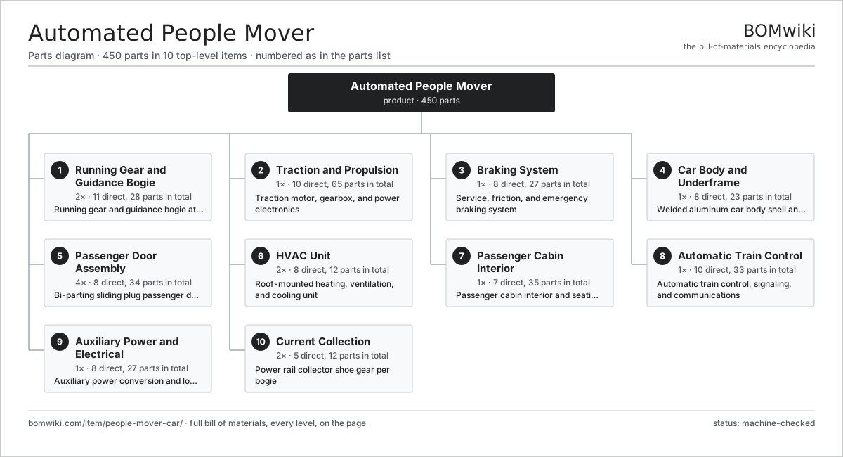
| # | Part | Qty | What it does |
|---|---|---|---|
| 1 | Running Gear and Guidance Bogie 11 parts | 2× | Running gear and guidance bogie at each end of the car |
| 2 | Traction and Propulsion 10 parts | 1× | Traction motor, gearbox, and power electronics |
| 3 | Braking System 8 parts | 1× | Service, friction, and emergency braking system |
| 4 | Car Body and Underframe 8 parts | 1× | Welded aluminum car body shell and underframe |
| 5 | Passenger Door Assembly 8 parts | 4× | Bi-parting sliding plug passenger door assembly |
| 6 | HVAC Unit 8 parts | 2× | Roof-mounted heating, ventilation, and cooling unit |
| 7 | Passenger Cabin Interior 7 parts | 1× | Passenger cabin interior and seating |
| 8 | Automatic Train Control 10 parts | 1× | Automatic train control, signaling, and communications |
| 9 | Auxiliary Power and Electrical 8 parts | 1× | Auxiliary power conversion and low-voltage electrical |
| 10 | Current Collection 5 parts | 2× | Power rail collector shoe gear per bogie |
3D model
No 3D model yet. Have a CAD file of this? Add a 3D model. STL renders right on this page; STEP, FreeCAD, and OpenSCAD sources are welcome too (openly licensed, like all 3D models on BOMwiki).
Build & assembly graph
expand / collapse · shared sub-assemblies converge · links to related products · est. labourTap an assembly to expand/collapse · tap a part to open it · use “Open page” for any node · drag to pan, scroll to zoom.
Bill of materials for Automated People Mover
10 top-level lines · 104 rows shown · 450 parts total · indented to 3 levels| # | Item / sub-assembly | Part no. | Qty/assy | Ext. qty | Parts | Type |
|---|---|---|---|---|---|---|
| 1 | Running Gear and Guidance Bogie 11 parts | people-mover-car-bogie | 2× | 2 | 28 | assembly |
| 1.1 | Bogie Frame | people-mover-car-bogie-frame | 1× | 2 | · | part |
| 1.2 | Load Tire | people-mover-car-load-tire | 2× | 4 | · | part |
| 1.3 | Load Wheel Hub | people-mover-car-load-wheel-hub | 2× | 4 | · | part |
| 1.4 | Guide Tire | people-mover-car-guide-tire | 4× | 8 | · | part |
| 1.5 | Guidance Arm | people-mover-car-guide-arm | 2× | 4 | · | part |
| 1.6 | Switching Bar | people-mover-car-switch-bar | 1× | 2 | · | part |
| 1.7 | Air Spring | people-mover-car-air-spring | 2× | 4 | · | part |
| 1.8 | Coil Spring | coil-spring | 4× | 8 | · | part |
| 1.9 | Ball Bearing | ball-bearing | 8× | 16 | · | part |
| 1.10 | Center Pivot | people-mover-car-pivot | 1× | 2 | · | part |
| 1.11 | Fastener Set | fastener-set | 1× | 2 | · | part |
| 2 | Traction and Propulsion 10 parts | people-mover-car-propulsion | 1× | 1 | 65 | assembly |
| 2.1 | Traction Motor | people-mover-car-traction-motor | 2× | 2 | · | part |
| 2.2 | Traction Inverter | people-mover-car-traction-inverter | 1× | 1 | · | part |
| 2.3 | Gearbox Housing | gearbox-housing | 2× | 2 | · | part |
| 2.4 | Helical Gear Pair | gear-pair | 2× | 2 | · | part |
| 2.5 | Stator Assembly 3 parts | stator-assembly | 2× | 2 | 3 | assembly |
| 2.5.1 | Stator Core (laminations) | stator-core | 1× | 2 | · | part |
| 2.5.2 | Copper Winding | copper-winding | 1× | 2 | · | part |
| 2.5.3 | Slot Insulation | stator-insulation | 1× | 2 | · | part |
| 2.6 | Rotor Assembly 4 parts | rotor-assembly | 2× | 2 | 19 | assembly |
| 2.6.1 | Rotor Shaft | rotor-shaft | 1× | 2 | · | part |
| 2.6.2 | Rotor Core | rotor-core | 1× | 2 | · | part |
| 2.6.3 | Neodymium Magnet | neodymium-magnet | 16× | 32 | · | part |
| 2.6.4 | Ball Bearing | ball-bearing | 1× | 2 | · | part |
| 2.7 | DC Link Filter | people-mover-car-line-filter | 1× | 1 | · | part |
| 2.8 | Oil Seal | oil-seal | 4× | 4 | · | part |
| 2.9 | Ball Bearing | ball-bearing | 8× | 8 | · | part |
| 2.10 | Traction Control Unit | people-mover-car-traction-control | 1× | 1 | · | part |
| 3 | Braking System 8 parts | people-mover-car-braking | 1× | 1 | 27 | assembly |
| 3.1 | Brake Caliper | people-mover-car-brake-caliper | 4× | 4 | · | part |
| 3.2 | Brake Disc | people-mover-car-brake-disc | 4× | 4 | · | part |
| 3.3 | Brake Pad | people-mover-car-brake-pad | 8× | 8 | · | part |
| 3.4 | Hydraulic Power Pack | people-mover-car-hydraulic-unit | 1× | 1 | · | part |
| 3.5 | Brake Control Unit | people-mover-car-brake-control | 1× | 1 | · | part |
| 3.6 | Spring Parking Brake | people-mover-car-spring-brake | 4× | 4 | · | part |
| 3.7 | Pressure Sensor | pressure-sensor | 4× | 4 | · | part |
| 3.8 | O-Ring Set | oring-set | 1× | 1 | · | part |
| 4 | Car Body and Underframe 8 parts | people-mover-car-body | 1× | 1 | 23 | assembly |
| 4.1 | Underframe | people-mover-car-underframe | 1× | 1 | · | part |
| 4.2 | Sidewall Panel | people-mover-car-sidewall | 2× | 2 | · | part |
| 4.3 | Roof Structure | people-mover-car-roof | 1× | 1 | · | part |
| 4.4 | End Module | people-mover-car-end-cab | 2× | 2 | · | part |
| 4.5 | Window Glazing | people-mover-car-window | 8× | 8 | · | part |
| 4.6 | Articulation Coupler | people-mover-car-coupler | 2× | 2 | · | part |
| 4.7 | Sheet Metal Panel | sheet-panel | 6× | 6 | · | part |
| 4.8 | Fastener Set | fastener-set | 1× | 1 | · | part |
| 5 | Passenger Door Assembly 8 parts | people-mover-car-doors | 4× | 4 | 34 | assembly |
| 5.1 | Door Leaf | people-mover-car-door-leaf | 2× | 8 | · | part |
| 5.2 | Door Operator | people-mover-car-door-operator | 1× | 4 | · | part |
| 5.3 | Ball Screw | ball-screw | 1× | 4 | · | part |
| 5.4 | Linear Guide Rail | linear-guide | 2× | 8 | · | part |
| 5.5 | Door Control Unit | people-mover-car-door-controller | 1× | 4 | · | part |
| 5.6 | Door Seal | people-mover-car-door-seal | 2× | 8 | · | part |
| 5.7 | Servo Motor 4 parts | servo-motor | 1× | 4 | 24 | assembly |
| 5.7.1 | Stator Assembly 3 parts + deeper › | stator-assembly | 1× | 4 | 3 | assembly |
| 5.7.2 | Rotor Assembly 4 parts + deeper › | rotor-assembly | 1× | 4 | 19 | assembly |
| 5.7.3 | Encoder | encoder | 1× | 4 | · | part |
| 5.7.4 | Motor Housing | motor-housing | 1× | 4 | · | part |
| 5.8 | Drive Belt | drive-belt | 1× | 4 | · | part |
| 6 | HVAC Unit 8 parts | people-mover-car-hvac | 2× | 2 | 12 | assembly |
| 6.1 | Refrigerant Compressor | people-mover-car-compressor | 1× | 2 | · | part |
| 6.2 | Condenser Coil | people-mover-car-condenser-coil | 1× | 2 | · | part |
| 6.3 | Evaporator Coil | people-mover-car-evaporator-coil | 1× | 2 | · | part |
| 6.4 | Blower Fan | people-mover-car-blower | 2× | 4 | · | part |
| 6.5 | Heating Element | heating-element | 2× | 4 | · | part |
| 6.6 | HVAC Controller | people-mover-car-hvac-control | 1× | 2 | · | part |
| 6.7 | Pressure Sensor | pressure-sensor | 2× | 4 | · | part |
| 6.8 | Air Filter | people-mover-car-air-filter | 2× | 4 | · | part |
| 7 | Passenger Cabin Interior 7 parts | people-mover-car-cabin | 1× | 1 | 35 | assembly |
| 7.1 | Passenger Seat | people-mover-car-seat | 12× | 12 | · | part |
| 7.2 | Grab Rail | people-mover-car-grab-rail | 6× | 6 | · | part |
| 7.3 | Floor Covering | people-mover-car-floor-covering | 1× | 1 | · | part |
| 7.4 | Ceiling Panel | people-mover-car-ceiling-panel | 4× | 4 | · | part |
| 7.5 | LED Light Fixture | people-mover-car-led-light | 8× | 8 | · | part |
| 7.6 | Passenger Information Display | people-mover-car-pis-display | 2× | 2 | · | part |
| 7.7 | LCD Panel | lcd-panel | 2× | 2 | · | part |
| 8 | Automatic Train Control 10 parts | people-mover-car-atc | 1× | 1 | 33 | assembly |
| 8.1 | Vehicle Onboard Controller | people-mover-car-vobc | 1× | 1 | · | part |
| 8.2 | Automatic Train Protection Unit | people-mover-car-atp | 1× | 1 | · | part |
| 8.3 | Balise Reader | people-mover-car-balise-reader | 2× | 2 | · | part |
| 8.4 | Speed Sensor | people-mover-car-speed-sensor | 4× | 4 | · | part |
| 8.5 | Communications Radio | people-mover-car-radio | 2× | 2 | · | part |
| 8.6 | Communications Antenna | people-mover-car-antenna | 2× | 2 | · | part |
| 8.7 | Bare PCB | pcb-bare | 6× | 6 | · | part |
| 8.8 | Microcontroller | mcu | 6× | 6 | · | part |
| 8.9 | SMD Passive (R/C/L) | smd-passives | 1× | 1 | · | part |
| 8.10 | Connector | connector | 8× | 8 | · | part |
| 9 | Auxiliary Power and Electrical 8 parts | people-mover-car-aux-power | 1× | 1 | 27 | assembly |
| 9.1 | Auxiliary Converter | people-mover-car-aux-converter | 1× | 1 | · | part |
| 9.2 | Backup Battery | people-mover-car-battery | 1× | 1 | · | part |
| 9.3 | Power Supply | power-supply | 2× | 2 | · | part |
| 9.4 | Battery Charger | people-mover-car-battery-charger | 1× | 1 | · | part |
| 9.5 | Electrical Junction Box | people-mover-car-junction-box | 2× | 2 | · | part |
| 9.6 | Wire Bundle | wire-bundle | 4× | 4 | · | part |
| 9.7 | Relay | relay | 6× | 6 | · | part |
| 9.8 | Connector | connector | 10× | 10 | · | part |
| 10 | Current Collection 5 parts | people-mover-car-current-collection | 2× | 2 | 12 | assembly |
| 10.1 | Collector Shoe | people-mover-car-collector-shoe | 2× | 4 | · | part |
| 10.2 | Collector Arm | people-mover-car-shoe-arm | 2× | 4 | · | part |
| 10.3 | Shoe Insulator | people-mover-car-shoe-insulator | 4× | 8 | · | part |
| 10.4 | Coil Spring | coil-spring | 2× | 4 | · | part |
| 10.5 | Shoe Feed Cable | people-mover-car-shoe-cable | 2× | 4 | · | part |
Related products
same domain, ranked by shared parts Bus Rapid Transit Vehicle
4,251 parts · shares 22 with this page
Bus Rapid Transit Vehicle
4,251 parts · shares 22 with this page
 Rubber-Tyred Metro Car
3,067 parts · shares 22 with this page
Rubber-Tyred Metro Car
3,067 parts · shares 22 with this page
 Overhead Wire Maintenance Car
230 parts · shares 21 with this page
Overhead Wire Maintenance Car
230 parts · shares 21 with this page
 Rail Inspection Trolley
251 parts · shares 21 with this page
Rail Inspection Trolley
251 parts · shares 21 with this page
 Electric Bus
4,481 parts · shares 21 with this page
Electric Bus
4,481 parts · shares 21 with this page
 Party Bus
696 parts · shares 21 with this page
Party Bus
696 parts · shares 21 with this page
Sourcing: possible vendors
Browse the supplier directory → Prices, MOQ, and lead times are algorithmic estimates, not quotes, and not claims about these companies. Company mappings are curated by keyword; est. price band $500k–$60M. How estimates work| Vendor | HQ | Specialty | MOQ | Lead time |
|---|---|---|---|---|
|
🇨🇳CRRC
crrcgc.cc ↗
|
Beijing, CN | Rolling stock & rail systems | made to order | 40–72 wks |
|
🇫🇷Alstom
alstom.com ↗
|
Saint-Ouen, FR | Rail rolling stock | made to order | 40–72 wks |
| mobility.siemens.com ↗ | Munich, DE | Rail systems | made to order | 40–72 wks |
| stadlerrail.com ↗ | Bussnang, CH | Rail rolling stock | made to order | 40–72 wks |
|
🇺🇸Wabtec
wabteccorp.com ↗
|
Pittsburgh, US | Rail equipment | made to order | 40–72 wks |
1,129-word article