Rubber-Tyred Metro Car
ProductOverview
A rubber-tyred metro car is a self-propelled urban rail vehicle that rolls on pneumatic rubber running tires instead of steel wheels on steel rail. The arrangement was pioneered on the Paris Metro in the 1950s and is used on several Paris lines, the Montreal Metro, the Mexico City Metro, the Santiago Metro, and on the driverless Rubber-Tyred Metro Car systems of the VAL family in Lille and at many airports. The vehicle keeps a complete set of conventional flanged steel wheels and steel rails as a backup, so the track has both flat rolling ways for the tires and ordinary running rails underneath. A typical car is 16–18 m long, about 2.5 m wide, and runs at a service speed of 70–80 km/h drawing 750 V DC traction power.
The car is built around ten major systems: the Carbody Shell, two Running / Guide Bogie units that carry the running, guide and safety wheels, the Traction Drive on each bogie, the Current Collection System system, the Traction Control Electronics electronics, the Brake System, roof Roof HVAC Unit units, the Passenger Interior, the Low-Voltage Electrical supply, and the Coupler & Gangway at each end.
Running gear and guidance
The defining hardware is the Running / Guide Bogie. Each bogie carries four Pneumatic Running Wheel assemblies. Each running wheel is a Running Tire (Pneumatic), a reinforced pneumatic tire inflated to roughly 8.5 bar, mounted on a Running Wheel Rim on Ball Bearing supports. The running tires carry the full weight of the car and roll on a flat concrete or steel rolling way, which gives the line its ride feel and most of its traction. Inside each tire is a Run-Flat Safety Insert, a solid rubber run-flat ring that supports the rim if the tire deflates, letting the car limp to the next station rather than dropping suddenly. A Pressure Sensor on each wheel warns the driver of pressure loss.
Steering is the second distinctive feature. A steel-wheel bogie is guided by the flanges on its wheels, but a rubber tire has no flange, so the rubber-tyred bogie is steered by eight horizontal guide tires, two per Horizontal Guide-Tire Arm. Each guide arm carries a small Horizontal Guide Tire on a sprung Guide Tire Hub that bears outward against a vertical side guide bar running alongside the track. The two guide bars on either side hold the bogie centered, feed in the lateral forces needed to follow curves, and operate the points at junctions. Because the running tires are insulating, the guide bars usually carry the traction power as well, which is why the Current Collection System shoes ride on bars next to the guides.
The third feature is the fallback. Concentric with each running tire is a Steel Safety Wheel, a normal flanged steel wheel with a Wheel Flange riding a few centimetres above an ordinary steel rail. In normal running the steel wheel does not touch the rail. If a running tire deflates, the steel wheel settles onto the rail and supports the car on the conventional steel system, and the flange takes over guidance from the guide tires. The steel wheels also carry the car through the steel-rail switches and crossings where the rolling way is interrupted. Ride and curve forces are softened by the Primary Suspension at each wheel and by the Secondary Air Suspension, whose Air Spring (Bellows) bellows hold the floor at a constant height as passengers board.
Traction and current collection
Each bogie has a Traction Drive. A Traction Motor (3-Phase Induction), a force-ventilated three-phase induction motor of roughly 140–180 kW continuous, drives a running-wheel axle through a single-stage Reduction Gearbox and a flexible Flexible Drive Coupling. The motor reuses a shared Stator Assembly and Rotor Assembly in its own Traction Motor Housing. The high grip of rubber on concrete is the main engineering reason for the whole layout: the adhesion is far higher than steel on steel, so the car accelerates and brakes harder and can climb grades of 6–7%, against roughly 4% for a conventional metro. That lets designers route lines with steeper ramps and tighter level changes.
Because the running tires insulate the wheels from the track, power cannot come up through the rail as it does on a steel-wheel metro. Instead the Current Collection System system uses sliding Lateral Power Collector Shoe collectors that press sideways against lateral power bars mounted next to the guide bars. Each shoe carries a replaceable Carbon Contact Shoe on sprung Sprung Shoe Gear, and a Negative Return Brush sends the negative return current back through a steel running rail. The 750 V DC feed passes through a HV Junction Box with a High-Speed Line Breaker and Surge Arrester before reaching the inverters.
Power control and braking
The Traction Control Electronics converts the 750 V DC supply into variable-voltage variable-frequency three-phase power for the induction motors. The VVVF Traction Inverter uses a IGBT Power Stack of six high-voltage IGBT modules, switched by gate drivers under the Inverter Control Board board, with a DC Line Filter smoothing the DC link. The Train Control Unit manages tractive effort and wheel-slip, while the Automatic Train Control Unit reads trackside signalling through a Track Balise / Beacon Antenna and enforces speed limits, which on driverless lines runs the whole train.
Braking is blended. The first stage is regenerative braking through the traction motors, which return energy to the 750 V DC supply and do most of the routine stopping. Below the speed where regeneration fades, and for harder stops, the Brake System applies friction. Each running wheel has a Friction Disc Brake with a Brake Disc and Brake Caliper, driven by a Brake Actuator Cylinder fed from the Air Compressor Unit and Air Reservoir. For emergencies, a Emergency Track Brake clamps a Track Brake Shoe against the steel safety rail. The Brake Control Unit unit blends these stages so the deceleration the passenger feels stays smooth across the handover.
Carbody, interior and operation
The Carbody Shell is a welded aluminium-alloy or stainless shell on a steel underframe, with a Body Bolster over each bogie and a Crash Energy Absorber at the cab ends that absorbs collision energy under EN 15227. The Passenger Interior is laid out for high standing capacity: longitudinal Passenger Bench Seat benches, Grab Pole / Stanchion stanchions, LED Light Strip lighting, and a Passenger Information System for announcements. Wide Sliding Plug Door System plug doors driven by a Electric Door Drive give fast boarding at short station dwells. Roof Roof HVAC Unit units of 25–35 kW cooling each keep the saloon comfortable in tunnels.
The reason to accept the complexity of two wheel systems is ride and operation. Rubber tires run quieter than steel on steel, and the high grip gives faster station-to-station times and steeper permissible grades, which matters for hilly cities and for the tight vertical alignments of airport people-movers. The penalties are higher rolling resistance and energy use, tires that wear and must be replaced, and sensitivity to heat in long tunnels, so the choice is made line by line. Cars are joined into trains through the Automatic Coupler and walked through by passengers across the Inter-Car Gangway.
Rubber-Tyred Metro Car parts and their functions
10 top-level parts · 3,067 parts in total · full bill of materials below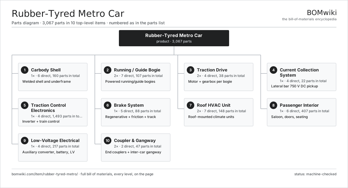
| # | Part | Qty | What it does |
|---|---|---|---|
| 1 | Carbody Shell 6 parts | 1× | Welded shell and underframe |
| 2 | Running / Guide Bogie 7 parts | 2× | Powered running/guide bogies |
| 3 | Traction Drive 4 parts | 2× | Motor + gearbox per bogie |
| 4 | Current Collection System 4 parts | 1× | Lateral bar 750 V DC pickup |
| 5 | Traction Control Electronics 4 parts | 1× | Inverter + train control |
| 6 | Brake System 5 parts | 1× | Regenerative + friction + track |
| 7 | Roof HVAC Unit 7 parts | 2× | Roof-mounted climate units |
| 8 | Passenger Interior 6 parts | 1× | Saloon, doors, seating |
| 9 | Low-Voltage Electrical 4 parts | 1× | Auxiliary converter, battery, LV |
| 10 | Coupler & Gangway 2 parts | 2× | End couplers + inter-car gangway |
3D model
No 3D model yet. Have a CAD file of this? Add a 3D model. STL renders right on this page; STEP, FreeCAD, and OpenSCAD sources are welcome too (openly licensed, like all 3D models on BOMwiki).
Build & assembly graph
expand / collapse · shared sub-assemblies converge · links to related products · est. labourTap an assembly to expand/collapse · tap a part to open it · use “Open page” for any node · drag to pan, scroll to zoom.
Bill of materials for Rubber-Tyred Metro Car
10 top-level lines · 191 rows shown · 3,067 parts total · indented to 3 levels| # | Item / sub-assembly | Part no. | Qty/assy | Ext. qty | Parts | Type |
|---|---|---|---|---|---|---|
| 1 | Carbody Shell 6 parts | rubber-tyred-metro-carbody | 1× | 1 | 160 | assembly |
| 1.1 | Underframe 4 parts | rubber-tyred-metro-underframe | 1× | 1 | 18 | assembly |
| 1.1.1 | Sole Bar | rubber-tyred-metro-sole-bar | 2× | 2 | · | part |
| 1.1.2 | Body Bolster | rubber-tyred-metro-bolster | 2× | 2 | · | part |
| 1.1.3 | Underframe Crossbeam | rubber-tyred-metro-crossbeam | 6× | 6 | · | part |
| 1.1.4 | Sheet Metal Panel | sheet-panel | 8× | 8 | · | part |
| 1.2 | Side Wall Panel 3 parts | rubber-tyred-metro-side-wall | 2× | 2 | 12 | assembly |
| 1.2.1 | Sheet Metal Panel | sheet-panel | 4× | 8 | · | part |
| 1.2.2 | Saloon Window Glazing | rubber-tyred-metro-window-glazing | 6× | 12 | · | part |
| 1.2.3 | Door Aperture Frame | rubber-tyred-metro-door-aperture | 2× | 4 | · | part |
| 1.3 | Roof Structure 3 parts | rubber-tyred-metro-roof-structure | 1× | 1 | 9 | assembly |
| 1.3.1 | Sheet Metal Panel | sheet-panel | 6× | 6 | · | part |
| 1.3.2 | HVAC Mounting Well | rubber-tyred-metro-hvac-well | 2× | 2 | · | part |
| 1.3.3 | Roof Cable Conduit | rubber-tyred-metro-roof-conduit | 1× | 1 | · | part |
| 1.4 | Driving Cab End 4 parts | rubber-tyred-metro-end-cab | 1× | 1 | 99 | assembly |
| 1.4.1 | Crash Energy Absorber | rubber-tyred-metro-crush-zone | 1× | 1 | · | part |
| 1.4.2 | Driver Console 4 parts + deeper › | rubber-tyred-metro-cab-console | 1× | 1 | 11 | assembly |
| 1.4.3 | Cab Windscreen | rubber-tyred-metro-windscreen | 1× | 1 | · | part |
| 1.4.4 | Cab Display Unit 4 parts + deeper › | rubber-tyred-metro-cab-display | 2× | 2 | 43 | assembly |
| 1.5 | Floor Assembly 3 parts | rubber-tyred-metro-floor-assembly | 1× | 1 | 6 | assembly |
| 1.5.1 | Honeycomb Floor Panel | rubber-tyred-metro-floor-panel | 4× | 4 | · | part |
| 1.5.2 | Anti-Slip Floor Covering | rubber-tyred-metro-floor-covering | 1× | 1 | · | part |
| 1.5.3 | Acoustic Damping Mat | rubber-tyred-metro-acoustic-mat | 1× | 1 | · | part |
| 1.6 | Fastener Set | fastener-set | 4× | 4 | · | part |
| 2 | Running / Guide Bogie 7 parts | rubber-tyred-metro-bogie | 2× | 2 | 107 | assembly |
| 2.1 | Bogie Frame | rubber-tyred-metro-bogie-frame | 1× | 2 | · | part |
| 2.2 | Pneumatic Running Wheel 5 parts | rubber-tyred-metro-running-wheel | 4× | 8 | 6 | assembly |
| 2.2.1 | Running Tire (Pneumatic) | rubber-tyred-metro-running-tire | 1× | 8 | · | part |
| 2.2.2 | Run-Flat Safety Insert | rubber-tyred-metro-safety-insert | 1× | 8 | · | part |
| 2.2.3 | Running Wheel Rim | rubber-tyred-metro-wheel-rim | 1× | 8 | · | part |
| 2.2.4 | Ball Bearing | ball-bearing | 2× | 16 | · | part |
| 2.2.5 | Pressure Sensor | pressure-sensor | 1× | 8 | · | part |
| 2.3 | Horizontal Guide-Tire Arm 5 parts | rubber-tyred-metro-guide-arm | 4× | 8 | 6 | assembly |
| 2.3.1 | Horizontal Guide Tire | rubber-tyred-metro-guide-tire | 1× | 8 | · | part |
| 2.3.2 | Guide Tire Hub | rubber-tyred-metro-guide-hub | 1× | 8 | · | part |
| 2.3.3 | Ball Bearing | ball-bearing | 2× | 16 | · | part |
| 2.3.4 | Coil Spring | coil-spring | 1× | 8 | · | part |
| 2.3.5 | Pressure Sensor | pressure-sensor | 1× | 8 | · | part |
| 2.4 | Steel Safety Wheel 3 parts | rubber-tyred-metro-safety-wheel | 4× | 8 | 4 | assembly |
| 2.4.1 | Steel Wheel Tread | rubber-tyred-metro-steel-tyre | 1× | 8 | · | part |
| 2.4.2 | Wheel Flange | rubber-tyred-metro-wheel-flange | 1× | 8 | · | part |
| 2.4.3 | Ball Bearing | ball-bearing | 2× | 16 | · | part |
| 2.5 | Primary Suspension 3 parts | rubber-tyred-metro-primary-suspension | 4× | 8 | 6 | assembly |
| 2.5.1 | Coil Spring | coil-spring | 1× | 8 | · | part |
| 2.5.2 | Chevron Rubber Pad | rubber-tyred-metro-rubber-pad | 2× | 16 | · | part |
| 2.5.3 | Hydraulic Damper 3 parts + deeper › | rubber-tyred-metro-damper | 1× | 8 | 3 | assembly |
| 2.6 | Secondary Air Suspension 3 parts | rubber-tyred-metro-secondary-suspension | 2× | 4 | 3 | assembly |
| 2.6.1 | Air Spring (Bellows) | rubber-tyred-metro-air-spring | 1× | 4 | · | part |
| 2.6.2 | Levelling Valve | rubber-tyred-metro-leveling-valve | 1× | 4 | · | part |
| 2.6.3 | Anti-Roll Bar | rubber-tyred-metro-anti-roll-bar | 1× | 4 | · | part |
| 2.7 | Stub Axle Assembly 3 parts | rubber-tyred-metro-axle-assembly | 2× | 4 | 6 | assembly |
| 2.7.1 | Stub Axle | rubber-tyred-metro-stub-axle | 2× | 8 | · | part |
| 2.7.2 | Wheel Hub | rubber-tyred-metro-wheel-hub | 2× | 8 | · | part |
| 2.7.3 | Ball Bearing | ball-bearing | 2× | 8 | · | part |
| 3 | Traction Drive 4 parts | rubber-tyred-metro-traction-drive | 2× | 2 | 38 | assembly |
| 3.1 | Traction Motor (3-Phase Induction) 6 parts | rubber-tyred-metro-traction-motor | 1× | 2 | 27 | assembly |
| 3.1.1 | Stator Assembly 3 parts + deeper › | stator-assembly | 1× | 2 | 3 | assembly |
| 3.1.2 | Rotor Assembly 4 parts + deeper › | rotor-assembly | 1× | 2 | 19 | assembly |
| 3.1.3 | Traction Motor Housing | rubber-tyred-metro-motor-housing | 1× | 2 | · | part |
| 3.1.4 | Ball Bearing | ball-bearing | 2× | 4 | · | part |
| 3.1.5 | Motor Cooling Fan | rubber-tyred-metro-cooling-fan | 1× | 2 | · | part |
| 3.1.6 | Wheel Speed Sensor | rubber-tyred-metro-speed-sensor | 1× | 2 | · | part |
| 3.2 | Reduction Gearbox 5 parts | rubber-tyred-metro-gearbox | 1× | 2 | 9 | assembly |
| 3.2.1 | Helical Gear Pair | gear-pair | 1× | 2 | · | part |
| 3.2.2 | Gearbox Housing | gearbox-housing | 1× | 2 | · | part |
| 3.2.3 | Ball Bearing | ball-bearing | 4× | 8 | · | part |
| 3.2.4 | Oil Seal | oil-seal | 2× | 4 | · | part |
| 3.2.5 | Gear Oil | rubber-tyred-metro-gear-oil | 1× | 2 | · | part |
| 3.3 | Flexible Drive Coupling | rubber-tyred-metro-coupling | 1× | 2 | · | part |
| 3.4 | Wheel Speed Sensor | rubber-tyred-metro-speed-sensor | 1× | 2 | · | part |
| 4 | Current Collection System 4 parts | rubber-tyred-metro-current-collection | 1× | 1 | 22 | assembly |
| 4.1 | Lateral Power Collector Shoe 2 parts | rubber-tyred-metro-power-shoe | 4× | 4 | 2 | assembly |
| 4.1.1 | Carbon Contact Shoe | rubber-tyred-metro-carbon-shoe | 1× | 4 | · | part |
| 4.1.2 | Shoe Feed Cable | rubber-tyred-metro-shoe-cable | 1× | 4 | · | part |
| 4.2 | Sprung Shoe Gear 2 parts | rubber-tyred-metro-shoe-gear | 4× | 4 | 2 | assembly |
| 4.2.1 | Coil Spring | coil-spring | 1× | 4 | · | part |
| 4.2.2 | Shoe Pivot Arm | rubber-tyred-metro-shoe-arm | 1× | 4 | · | part |
| 4.3 | Negative Return Brush | rubber-tyred-metro-return-brush | 2× | 2 | · | part |
| 4.4 | HV Junction Box 4 parts | rubber-tyred-metro-hv-junction | 1× | 1 | 4 | assembly |
| 4.4.1 | High-Speed Line Breaker | rubber-tyred-metro-line-breaker | 1× | 1 | · | part |
| 4.4.2 | Surge Arrester | rubber-tyred-metro-surge-arrester | 1× | 1 | · | part |
| 4.4.3 | HV Fuse | rubber-tyred-metro-hv-fuse | 1× | 1 | · | part |
| 4.4.4 | Wire Bundle | wire-bundle | 1× | 1 | · | part |
| 5 | Traction Control Electronics 4 parts | rubber-tyred-metro-traction-control | 1× | 1 | 1,493 | assembly |
| 5.1 | VVVF Traction Inverter 5 parts | rubber-tyred-metro-inverter | 2× | 2 | 535 | assembly |
| 5.1.1 | IGBT Power Stack | rubber-tyred-metro-igbt-stack | 1× | 2 | · | part |
| 5.1.2 | Gate Driver Board 3 parts + deeper › | rubber-tyred-metro-gate-driver | 6× | 12 | 62 | assembly |
| 5.1.3 | DC-Link Capacitor | rubber-tyred-metro-dc-link-cap | 4× | 8 | · | part |
| 5.1.4 | Inverter Control Board 4 parts + deeper › | rubber-tyred-metro-inverter-control | 1× | 2 | 155 | assembly |
| 5.1.5 | Liquid Cooling Block 2 parts + deeper › | rubber-tyred-metro-cooling-block | 1× | 2 | 3 | assembly |
| 5.2 | Train Control Unit 5 parts | rubber-tyred-metro-tcu | 1× | 1 | 236 | assembly |
| 5.2.1 | Bare PCB | pcb-bare | 2× | 2 | · | part |
| 5.2.2 | Microcontroller | mcu | 2× | 2 | · | part |
| 5.2.3 | Relay | relay | 8× | 8 | · | part |
| 5.2.4 | Connector | connector | 24× | 24 | · | part |
| 5.2.5 | SMD Passive (R/C/L) | smd-passives | 200× | 200 | · | part |
| 5.3 | DC Line Filter 2 parts | rubber-tyred-metro-line-filter | 1× | 1 | 3 | assembly |
| 5.3.1 | Filter Reactor | rubber-tyred-metro-filter-reactor | 1× | 1 | · | part |
| 5.3.2 | DC-Link Capacitor | rubber-tyred-metro-dc-link-cap | 2× | 2 | · | part |
| 5.4 | Automatic Train Control Unit 5 parts | rubber-tyred-metro-atc-unit | 1× | 1 | 184 | assembly |
| 5.4.1 | Bare PCB | pcb-bare | 2× | 2 | · | part |
| 5.4.2 | Microcontroller | mcu | 3× | 3 | · | part |
| 5.4.3 | Track Balise / Beacon Antenna | rubber-tyred-metro-balise-antenna | 1× | 1 | · | part |
| 5.4.4 | Connector | connector | 18× | 18 | · | part |
| 5.4.5 | SMD Passive (R/C/L) | smd-passives | 160× | 160 | · | part |
| 6 | Brake System 5 parts | rubber-tyred-metro-brake-system | 1× | 1 | 88 | assembly |
| 6.1 | Brake Control Unit 5 parts | rubber-tyred-metro-brake-control | 1× | 1 | 17 | assembly |
| 6.1.1 | Bare PCB | pcb-bare | 1× | 1 | · | part |
| 6.1.2 | Microcontroller | mcu | 2× | 2 | · | part |
| 6.1.3 | Pressure Sensor | pressure-sensor | 4× | 4 | · | part |
| 6.1.4 | Relay | relay | 6× | 6 | · | part |
| 6.1.5 | Brake Solenoid Valve | rubber-tyred-metro-brake-valve | 4× | 4 | · | part |
| 6.2 | Friction Disc Brake 4 parts | rubber-tyred-metro-disc-brake | 4× | 4 | 8 | assembly |
| 6.2.1 | Brake Disc | rubber-tyred-metro-brake-disc | 1× | 4 | · | part |
| 6.2.2 | Brake Caliper 3 parts + deeper › | rubber-tyred-metro-brake-caliper | 1× | 4 | 4 | assembly |
| 6.2.3 | Brake Pad | rubber-tyred-metro-brake-pad | 2× | 8 | · | part |
| 6.2.4 | Brake Actuator Cylinder | rubber-tyred-metro-brake-cylinder | 1× | 4 | · | part |
| 6.3 | Emergency Track Brake 3 parts | rubber-tyred-metro-track-brake | 2× | 2 | 5 | assembly |
| 6.3.1 | Track Brake Shoe | rubber-tyred-metro-track-shoe | 2× | 4 | · | part |
| 6.3.2 | Brake Actuator Cylinder | rubber-tyred-metro-brake-cylinder | 1× | 2 | · | part |
| 6.3.3 | Coil Spring | coil-spring | 2× | 4 | · | part |
| 6.4 | Air Compressor Unit 4 parts | rubber-tyred-metro-air-compressor | 1× | 1 | 27 | assembly |
| 6.4.1 | Compressor Pump | rubber-tyred-metro-compressor-pump | 1× | 1 | · | part |
| 6.4.2 | Air Dryer | rubber-tyred-metro-air-dryer | 1× | 1 | · | part |
| 6.4.3 | Servo Motor 4 parts + deeper › | servo-motor | 1× | 1 | 24 | assembly |
| 6.4.4 | Pressure Sensor | pressure-sensor | 1× | 1 | · | part |
| 6.5 | Air Reservoir | rubber-tyred-metro-air-reservoir | 2× | 2 | · | part |
| 7 | Roof HVAC Unit 7 parts | rubber-tyred-metro-hvac | 2× | 2 | 148 | assembly |
| 7.1 | HVAC Scroll Compressor | rubber-tyred-metro-hvac-compressor | 1× | 2 | · | part |
| 7.2 | Condenser Coil | rubber-tyred-metro-condenser-coil | 1× | 2 | · | part |
| 7.3 | Evaporator Coil | rubber-tyred-metro-evaporator-coil | 1× | 2 | · | part |
| 7.4 | HVAC Blower 3 parts | rubber-tyred-metro-blower | 2× | 4 | 27 | assembly |
| 7.4.1 | Servo Motor 4 parts + deeper › | servo-motor | 1× | 4 | 24 | assembly |
| 7.4.2 | Centrifugal Blower Wheel | rubber-tyred-metro-blower-wheel | 1× | 4 | · | part |
| 7.4.3 | Ball Bearing | ball-bearing | 2× | 8 | · | part |
| 7.5 | Heating Element | heating-element | 2× | 4 | · | part |
| 7.6 | HVAC Controller 5 parts | rubber-tyred-metro-hvac-control | 1× | 2 | 87 | assembly |
| 7.6.1 | Bare PCB | pcb-bare | 1× | 2 | · | part |
| 7.6.2 | Microcontroller | mcu | 1× | 2 | · | part |
| 7.6.3 | Relay | relay | 4× | 8 | · | part |
| 7.6.4 | Pressure Sensor | pressure-sensor | 1× | 2 | · | part |
| 7.6.5 | SMD Passive (R/C/L) | smd-passives | 80× | 160 | · | part |
| 7.7 | HVAC Air Filter | rubber-tyred-metro-air-filter | 2× | 4 | · | part |
| 8 | Passenger Interior 6 parts | rubber-tyred-metro-interior | 1× | 1 | 407 | assembly |
| 8.1 | Sliding Plug Door System 5 parts | rubber-tyred-metro-door-system | 4× | 4 | 86 | assembly |
| 8.1.1 | Door Leaf | rubber-tyred-metro-door-leaf | 2× | 8 | · | part |
| 8.1.2 | Electric Door Drive 3 parts + deeper › | rubber-tyred-metro-door-drive | 1× | 4 | 26 | assembly |
| 8.1.3 | Door Control Unit 4 parts + deeper › | rubber-tyred-metro-door-controller | 1× | 4 | 54 | assembly |
| 8.1.4 | Door Edge Seal | rubber-tyred-metro-door-seal | 2× | 8 | · | part |
| 8.1.5 | Linear Guide Rail | linear-guide | 2× | 8 | · | part |
| 8.2 | Passenger Bench Seat 2 parts | rubber-tyred-metro-seat | 12× | 12 | 3 | assembly |
| 8.2.1 | Moulded Seat Shell | rubber-tyred-metro-seat-shell | 1× | 12 | · | part |
| 8.2.2 | Seat Mount Bracket | rubber-tyred-metro-seat-mount | 2× | 24 | · | part |
| 8.3 | Grab Pole / Stanchion | rubber-tyred-metro-grab-pole | 8× | 8 | · | part |
| 8.4 | LED Saloon Lighting 2 parts | rubber-tyred-metro-lighting | 1× | 1 | 5 | assembly |
| 8.4.1 | LED Light Strip | rubber-tyred-metro-led-strip | 4× | 4 | · | part |
| 8.4.2 | Power Supply | power-supply | 1× | 1 | · | part |
| 8.5 | Passenger Information System 4 parts | rubber-tyred-metro-pis | 1× | 1 | 8 | assembly |
| 8.5.1 | LCD Panel | lcd-panel | 2× | 2 | · | part |
| 8.5.2 | PA Speaker | rubber-tyred-metro-pa-speaker | 4× | 4 | · | part |
| 8.5.3 | Bare PCB | pcb-bare | 1× | 1 | · | part |
| 8.5.4 | Microcontroller | mcu | 1× | 1 | · | part |
| 8.6 | Interior Wall Panel | rubber-tyred-metro-wall-panel | 6× | 6 | · | part |
| 9 | Low-Voltage Electrical 4 parts | rubber-tyred-metro-lv-electrical | 1× | 1 | 217 | assembly |
| 9.1 | Static Auxiliary Converter 5 parts | rubber-tyred-metro-aux-converter | 1× | 1 | 9 | assembly |
| 9.1.1 | Bare PCB | pcb-bare | 2× | 2 | · | part |
| 9.1.2 | IGBT Power Stack | rubber-tyred-metro-igbt-stack | 1× | 1 | · | part |
| 9.1.3 | DC-Link Capacitor | rubber-tyred-metro-dc-link-cap | 4× | 4 | · | part |
| 9.1.4 | Power Supply | power-supply | 1× | 1 | · | part |
| 9.1.5 | Auxiliary Transformer | rubber-tyred-metro-aux-transformer | 1× | 1 | · | part |
| 9.2 | Backup Battery (Ni-Cd) 2 parts | rubber-tyred-metro-battery | 1× | 1 | 81 | assembly |
| 9.2.1 | Ni-Cd Cell | rubber-tyred-metro-battery-cell | 80× | 80 | · | part |
| 9.2.2 | Battery Tray | rubber-tyred-metro-battery-tray | 1× | 1 | · | part |
| 9.3 | LV Wiring Harness 3 parts | rubber-tyred-metro-lv-harness | 1× | 1 | 77 | assembly |
| 9.3.1 | Wire Bundle | wire-bundle | 1× | 1 | · | part |
| 9.3.2 | Connector | connector | 60× | 60 | · | part |
| 9.3.3 | Relay | relay | 16× | 16 | · | part |
| 9.4 | LV Distribution Box 3 parts | rubber-tyred-metro-distribution-box | 1× | 1 | 50 | assembly |
| 9.4.1 | Miniature Circuit Breaker | rubber-tyred-metro-breaker | 12× | 12 | · | part |
| 9.4.2 | Relay | relay | 8× | 8 | · | part |
| 9.4.3 | Connector | connector | 30× | 30 | · | part |
| 10 | Coupler & Gangway 2 parts | rubber-tyred-metro-coupler-gangway | 2× | 2 | 47 | assembly |
| 10.1 | Automatic Coupler 4 parts | rubber-tyred-metro-coupler | 1× | 2 | 44 | assembly |
| 10.1.1 | Coupler Head | rubber-tyred-metro-coupler-head | 1× | 2 | · | part |
| 10.1.2 | Draft Gear (Energy Absorber) | rubber-tyred-metro-draft-gear | 1× | 2 | · | part |
| 10.1.3 | Electrical Coupler 2 parts + deeper › | rubber-tyred-metro-elec-coupler | 1× | 2 | 41 | assembly |
| 10.1.4 | Pneumatic Coupler | rubber-tyred-metro-air-coupler | 1× | 2 | · | part |
| 10.2 | Inter-Car Gangway 3 parts | rubber-tyred-metro-gangway | 1× | 2 | 3 | assembly |
| 10.2.1 | Gangway Bellows | rubber-tyred-metro-bellows | 1× | 2 | · | part |
| 10.2.2 | Bridge Plate | rubber-tyred-metro-bridge-plate | 1× | 2 | · | part |
| 10.2.3 | Gangway Frame | rubber-tyred-metro-gangway-frame | 1× | 2 | · | part |
Related products
same domain, ranked by shared parts Automated People Mover
450 parts · shares 22 with this page
Automated People Mover
450 parts · shares 22 with this page
 Bus Rapid Transit Vehicle
4,251 parts · shares 22 with this page
Bus Rapid Transit Vehicle
4,251 parts · shares 22 with this page
 Overhead Wire Maintenance Car
230 parts · shares 21 with this page
Overhead Wire Maintenance Car
230 parts · shares 21 with this page
 Rail Inspection Trolley
251 parts · shares 21 with this page
Rail Inspection Trolley
251 parts · shares 21 with this page
 Electric Bus
4,481 parts · shares 21 with this page
Electric Bus
4,481 parts · shares 21 with this page
 Party Bus
696 parts · shares 21 with this page
Party Bus
696 parts · shares 21 with this page
Sourcing: possible vendors
Browse the supplier directory → Prices, MOQ, and lead times are algorithmic estimates, not quotes, and not claims about these companies. Company mappings are curated by keyword; est. price band $500k–$60M. How estimates work| Vendor | HQ | Specialty | MOQ | Lead time |
|---|---|---|---|---|
|
🇨🇳CRRC
crrcgc.cc ↗
|
Beijing, CN | Rolling stock & rail systems | made to order | 40–72 wks |
|
🇫🇷Alstom
alstom.com ↗
|
Saint-Ouen, FR | Rail rolling stock | made to order | 40–72 wks |
| mobility.siemens.com ↗ | Munich, DE | Rail systems | made to order | 40–72 wks |
| stadlerrail.com ↗ | Bussnang, CH | Rail rolling stock | made to order | 40–72 wks |
|
🇺🇸Wabtec
wabteccorp.com ↗
|
Pittsburgh, US | Rail equipment | made to order | 40–72 wks |
1,352-word article