Commuter EMU
ProductOverview
A commuter electric multiple unit is a self-propelled passenger train in which traction equipment is spread along the cars rather than concentrated in a separate locomotive. Power arrives from an overhead contact wire, usually at 25-kV 50-Hz AC, through the Pantograph on the roof. From there it passes through the Main Transformer and the Traction Converter to the three-phase motors mounted in the Powered Bogie. Distributing the drive across several cars gives high adhesion weight, strong acceleration from a stand, and the ability to clear short station spacing quickly, which is what suburban service demands.
The unit is built around the Carbody Shell, an aluminium bodyshell carried on a Powered Bogie at one end and a Trailer Bogie at the other in the common configuration. The Brake System blends regeneration with friction braking, the Saloon HVAC Unit conditions the saloon, and the Sliding Door Pair units move passengers in and out at each stop. Interior fit-out lives in the Passenger Saloon, while the Train Control & Management System supervises everything and the Auxiliary Power Supply feeds lights, doors, fans and control electronics. The End Coupler & Gangway at each car end joins the train mechanically, electrically and pneumatically.
Current collection and high-voltage circuit
The Pantograph raises a Pantograph Head carrying twin Carbon Contact Strip contacts against the contact wire. The Pantograph Arm Frame is pushed up by the Pneumatic Raise Cylinder and insulated from the roof by Roof Post Insulator posts. Collected current runs along the Roof HV Busbar to the Vacuum Circuit Breaker, the main protective switch that isolates the whole high-voltage circuit. The breaker uses a Vacuum Interrupter Bottle to quench the arc when it opens under load. Roof-mounted high-voltage gear is exposed to weather and to the full line voltage, so creepage distances and insulator selection are set by the worst expected pollution and humidity.
Traction chain
The Main Transformer steps the catenary voltage down to manageable levels across several windings: traction supply for the converter and lower-voltage auxiliary supply. Its Laminated Transformer Core and Oil Tank Housing sit underfloor, cooled by the Transformer Oil Cooler and a Coolant Pump. The Traction Converter then does the electrical work in two stages. The Line-Side Converter (4Q) is a four-quadrant rectifier that turns the single-phase AC into a stable DC link held by the DC Link Stage capacitor bank, and it can push energy back to the line during braking. The Motor-Side Inverter stages synthesize variable-frequency three-phase AC from the DC link to drive the motors. Each Traction Motor (3-phase AC) is a robust asynchronous machine of roughly 250 kW, geared to a wheelset through the Final Drive Gear Unit. Power semiconductors run hot, so the Converter Cooling Loop loop carries waste heat away through a radiator.
Running gear
The Powered Bogie frame carries two Traction Motor (3-phase AC) units, two Final Drive Gear Unit drives and two Wheelset assemblies. Each Wheelset runs in Axlebox bearings, sprung from the frame by Primary Suspension Coil coils. Above the frame, the Air Spring (secondary) secondary suspension carries the carbody and keeps floor height constant as the load changes through the Height Leveling Valve. Friction braking comes from Disc Brake Caliper units squeezing a Brake Disc on each axle. The Trailer Bogie is the same pattern without motors or gearboxes, used under the unpowered end of the car. Choosing which axles to motor is a design trade-off: more powered axles raise the adhesion weight available for acceleration, but they also add cost, mass and maintenance, so suburban fleets are usually built with about half their axles driven. The Monobloc Wheel is a forged monobloc steel disc that is reprofiled on a lathe as the tread and flange wear, and the Axle is a critical safety item inspected by ultrasound for fatigue cracks at fixed mileage intervals.
Braking, climate and doors
The Brake System is electrically blended. Under braking the traction converter runs the motors as generators and returns energy to the catenary; the Electronic Brake Control Unit tops up the missing effort with friction braking from the Disc Brake Caliper units, drawing compressed air from the Air Compressor and Air Reservoir tanks. Saloon comfort comes from the roof Saloon HVAC Unit packs, each with a HVAC Compressor, heating element and HVAC Blower. The Sliding Door Pair uses a Door Drive Mechanism built on a Servo Motor and Drive Belt, controlled by the Door Control Unit, which detects obstructions before closing.
Interior, control and auxiliaries
The Passenger Saloon mixes Seat Assembly units with standee space, Grab Pole supports and Passenger Information Display screens that show the next stop. The Train Control & Management System is a distributed network: a Central Control Computer talks to Remote I/O Module units through Train Ethernet Switch hardware, sequencing traction, braking, doors and auxiliaries across the trainset and reporting faults to the driver console. The Auxiliary Power Supply static converter feeds three-phase loads and charges the 12 V Battery bank through the Battery Charger, so the train keeps its lights, controls and door power even when the pantograph is briefly off the wire. The saloon layout itself is set by the service: dense urban work uses more standee space and fewer seats so that the dwell at each station stays short, while outer-suburban runs lean toward more Seat Assembly units for the longer ride. Wide Sliding Door Pair openings and level access between platform and floor keep boarding fast, which is what lets a high-frequency timetable hold its schedule. Variants of the same basic design exist for third-rail supply, where a Pantograph is replaced by a contact shoe collecting 750-V DC from a side rail, and for dual-voltage operation that can run under both 25-kV AC catenary and DC third rail on through routes.
Commuter EMU parts and their functions
14 top-level parts · 14,010 parts in total · full bill of materials below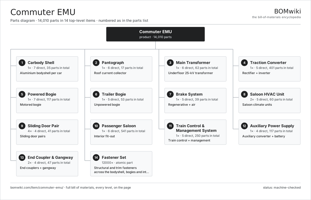
| # | Part | Qty | What it does |
|---|---|---|---|
| 1 | Carbody Shell 7 parts | 1× | Aluminium bodyshell per car |
| 2 | Pantograph 6 parts | 1× | Roof current collector |
| 3 | Main Transformer 6 parts | 1× | Underfloor 25-kV transformer |
| 4 | Traction Converter 5 parts | 1× | Rectifier + inverter |
| 5 | Powered Bogie 7 parts | 1× | Motored bogie |
| 6 | Trailer Bogie 5 parts | 1× | Unpowered bogie |
| 7 | Brake System 5 parts | 1× | Regenerative + air |
| 8 | Saloon HVAC Unit 5 parts | 2× | Saloon climate units |
| 9 | Sliding Door Pair 4 parts | 4× | Sliding door pairs |
| 10 | Passenger Saloon 6 parts | 1× | Interior fit-out |
| 11 | Train Control & Management System 5 parts | 1× | Train control + management |
| 12 | Auxiliary Power Supply 4 parts | 1× | Auxiliary converter + battery |
| 13 | End Coupler & Gangway 4 parts | 2× | End couplers + gangway |
| 14 | Fastener Set | 12000× | Structural and trim fasteners across the bodyshell, bogies and interior of one car |
3D model
No 3D model yet. Have a CAD file of this? Add a 3D model. STL renders right on this page; STEP, FreeCAD, and OpenSCAD sources are welcome too (openly licensed, like all 3D models on BOMwiki).
Build & assembly graph
expand / collapse · shared sub-assemblies converge · links to related products · est. labourTap an assembly to expand/collapse · tap a part to open it · use “Open page” for any node · drag to pan, scroll to zoom.
Bill of materials for Commuter EMU
14 top-level lines · 198 rows shown · 14,010 parts total · indented to 3 levels| # | Item / sub-assembly | Part no. | Qty/assy | Ext. qty | Parts | Type |
|---|---|---|---|---|---|---|
| 1 | Carbody Shell 7 parts | commuter-emu-carbody | 1× | 1 | 35 | assembly |
| 1.1 | Underframe | commuter-emu-underframe | 1× | 1 | · | part |
| 1.2 | Sidewall Panel | commuter-emu-sidewall | 2× | 2 | · | part |
| 1.3 | Roof Structure | commuter-emu-roof-structure | 1× | 1 | · | part |
| 1.4 | Cab End Structure 3 parts | commuter-emu-cab-end | 1× | 1 | 10 | assembly |
| 1.4.1 | Crashworthy End Structure | commuter-emu-crash-structure | 1× | 1 | · | part |
| 1.4.2 | Driver Console 4 parts + deeper › | commuter-emu-cab-console | 1× | 1 | 5 | assembly |
| 1.4.3 | Sheet Metal Panel | sheet-panel | 4× | 4 | · | part |
| 1.5 | Saloon Window | commuter-emu-window | 14× | 14 | · | part |
| 1.6 | Cab Windscreen | commuter-emu-windscreen | 1× | 1 | · | part |
| 1.7 | Fastener Set | fastener-set | 6× | 6 | · | part |
| 2 | Pantograph 6 parts | commuter-emu-pantograph | 1× | 1 | 17 | assembly |
| 2.1 | Pantograph Head 3 parts | commuter-emu-pan-head | 1× | 1 | 6 | assembly |
| 2.1.1 | Carbon Contact Strip | commuter-emu-carbon-strip | 2× | 2 | · | part |
| 2.1.2 | Pantograph Horn | commuter-emu-pan-horn | 2× | 2 | · | part |
| 2.1.3 | Coil Spring | coil-spring | 2× | 2 | · | part |
| 2.2 | Pantograph Arm Frame | commuter-emu-pan-frame | 1× | 1 | · | part |
| 2.3 | Pneumatic Raise Cylinder | commuter-emu-pan-raise-cylinder | 1× | 1 | · | part |
| 2.4 | Roof Post Insulator | commuter-emu-roof-insulator | 4× | 4 | · | part |
| 2.5 | Vacuum Circuit Breaker 3 parts | commuter-emu-vacuum-breaker | 1× | 1 | 4 | assembly |
| 2.5.1 | Vacuum Interrupter Bottle | commuter-emu-vacuum-interrupter | 1× | 1 | · | part |
| 2.5.2 | Breaker Actuator | commuter-emu-breaker-actuator | 1× | 1 | · | part |
| 2.5.3 | Relay | relay | 2× | 2 | · | part |
| 2.6 | Roof HV Busbar | commuter-emu-roof-busbar | 1× | 1 | · | part |
| 3 | Main Transformer 6 parts | commuter-emu-main-transformer | 1× | 1 | 62 | assembly |
| 3.1 | Laminated Transformer Core | commuter-emu-transformer-core | 1× | 1 | · | part |
| 3.2 | Copper Winding | copper-winding | 4× | 4 | · | part |
| 3.3 | Oil Tank Housing | commuter-emu-transformer-tank | 1× | 1 | · | part |
| 3.4 | Transformer Oil Cooler 3 parts | commuter-emu-oil-cooler | 1× | 1 | 53 | assembly |
| 3.4.1 | Radiator | radiator | 1× | 1 | · | part |
| 3.4.2 | Oil Cooler Fan 3 parts + deeper › | commuter-emu-cooler-fan | 2× | 2 | 24 | assembly |
| 3.4.3 | Oil Seal | oil-seal | 4× | 4 | · | part |
| 3.5 | Coolant Pump | coolant-pump | 1× | 1 | · | part |
| 3.6 | HV Bushing | commuter-emu-bushing | 2× | 2 | · | part |
| 4 | Traction Converter 5 parts | commuter-emu-traction-converter | 1× | 1 | 401 | assembly |
| 4.1 | Line-Side Converter (4Q) 4 parts | commuter-emu-line-converter | 1× | 1 | 185 | assembly |
| 4.1.1 | IGBT Power Module | igbt-module | 8× | 8 | · | part |
| 4.1.2 | Gate Driver Board 3 parts + deeper › | gate-driver-board | 2× | 2 | 87 | assembly |
| 4.1.3 | Power Inductor | power-inductor | 2× | 2 | · | part |
| 4.1.4 | Microcontroller | mcu | 1× | 1 | · | part |
| 4.2 | DC Link Stage 3 parts | commuter-emu-dc-link | 1× | 1 | 11 | assembly |
| 4.2.1 | DC-Link Capacitor | dc-link-cap | 8× | 8 | · | part |
| 4.2.2 | DC Link Busbar | commuter-emu-dc-busbar | 1× | 1 | · | part |
| 4.2.3 | DC Link Discharge Resistor | commuter-emu-discharge-resistor | 2× | 2 | · | part |
| 4.3 | Motor-Side Inverter 4 parts | commuter-emu-motor-inverter | 2× | 2 | 98 | assembly |
| 4.3.1 | IGBT Power Module | igbt-module | 6× | 12 | · | part |
| 4.3.2 | Gate Driver Board 3 parts + deeper › | gate-driver-board | 1× | 2 | 87 | assembly |
| 4.3.3 | DC-Link Capacitor | dc-link-cap | 4× | 8 | · | part |
| 4.3.4 | Microcontroller | mcu | 1× | 2 | · | part |
| 4.4 | Converter Cooling Loop 4 parts | commuter-emu-converter-cooling | 1× | 1 | 8 | assembly |
| 4.4.1 | Radiator | radiator | 1× | 1 | · | part |
| 4.4.2 | Coolant Pump | coolant-pump | 1× | 1 | · | part |
| 4.4.3 | Power Heatsink | commuter-emu-heatsink | 4× | 4 | · | part |
| 4.4.4 | O-Ring Set | oring-set | 2× | 2 | · | part |
| 4.5 | Converter Cabinet Frame | commuter-emu-converter-frame | 1× | 1 | · | part |
| 5 | Powered Bogie 7 parts | commuter-emu-powered-bogie | 1× | 1 | 117 | assembly |
| 5.1 | Bogie Frame (powered) | commuter-emu-bogie-frame | 1× | 1 | · | part |
| 5.2 | Traction Motor (3-phase AC) 5 parts | commuter-emu-traction-motor | 2× | 2 | 26 | assembly |
| 5.2.1 | Stator Assembly 3 parts + deeper › | stator-assembly | 1× | 2 | 3 | assembly |
| 5.2.2 | Rotor Assembly 4 parts + deeper › | rotor-assembly | 1× | 2 | 19 | assembly |
| 5.2.3 | Copper Winding | copper-winding | 1× | 2 | · | part |
| 5.2.4 | Ball Bearing | ball-bearing | 2× | 4 | · | part |
| 5.2.5 | Traction Motor Housing | commuter-emu-motor-housing | 1× | 2 | · | part |
| 5.3 | Final Drive Gear Unit 4 parts | commuter-emu-gear-unit | 2× | 2 | 6 | assembly |
| 5.3.1 | Helical Gear Pair | gear-pair | 1× | 2 | · | part |
| 5.3.2 | Gearbox Housing | gearbox-housing | 1× | 2 | · | part |
| 5.3.3 | Ball Bearing | ball-bearing | 2× | 4 | · | part |
| 5.3.4 | Oil Seal | oil-seal | 2× | 4 | · | part |
| 5.4 | Wheelset 3 parts | commuter-emu-wheelset | 2× | 2 | 13 | assembly |
| 5.4.1 | Axle | commuter-emu-axle | 1× | 2 | · | part |
| 5.4.2 | Monobloc Wheel | commuter-emu-wheel | 2× | 4 | · | part |
| 5.4.3 | Axlebox 3 parts + deeper › | commuter-emu-axlebox | 2× | 4 | 5 | assembly |
| 5.5 | Primary Suspension Coil | commuter-emu-primary-suspension | 4× | 4 | · | part |
| 5.6 | Air Spring (secondary) 3 parts | commuter-emu-air-spring | 2× | 2 | 3 | assembly |
| 5.6.1 | Rubber Air Bellows | commuter-emu-air-bellows | 1× | 2 | · | part |
| 5.6.2 | Height Leveling Valve | commuter-emu-leveling-valve | 1× | 2 | · | part |
| 5.6.3 | O-Ring Set | oring-set | 1× | 2 | · | part |
| 5.7 | Disc Brake Caliper 3 parts | commuter-emu-brake-caliper | 4× | 4 | 4 | assembly |
| 5.7.1 | Brake Disc | commuter-emu-brake-disc | 1× | 4 | · | part |
| 5.7.2 | Brake Pad | commuter-emu-brake-pad | 2× | 8 | · | part |
| 5.7.3 | Brake Cylinder | commuter-emu-brake-cylinder | 1× | 4 | · | part |
| 6 | Trailer Bogie 5 parts | commuter-emu-trailer-bogie | 1× | 1 | 53 | assembly |
| 6.1 | Bogie Frame (trailer) | commuter-emu-bogie-frame-trailer | 1× | 1 | · | part |
| 6.2 | Wheelset 3 parts | commuter-emu-wheelset | 2× | 2 | 13 | assembly |
| 6.2.1 | Axle | commuter-emu-axle | 1× | 2 | · | part |
| 6.2.2 | Monobloc Wheel | commuter-emu-wheel | 2× | 4 | · | part |
| 6.2.3 | Axlebox 3 parts + deeper › | commuter-emu-axlebox | 2× | 4 | 5 | assembly |
| 6.3 | Primary Suspension Coil | commuter-emu-primary-suspension | 4× | 4 | · | part |
| 6.4 | Air Spring (secondary) 3 parts | commuter-emu-air-spring | 2× | 2 | 3 | assembly |
| 6.4.1 | Rubber Air Bellows | commuter-emu-air-bellows | 1× | 2 | · | part |
| 6.4.2 | Height Leveling Valve | commuter-emu-leveling-valve | 1× | 2 | · | part |
| 6.4.3 | O-Ring Set | oring-set | 1× | 2 | · | part |
| 6.5 | Disc Brake Caliper 3 parts | commuter-emu-brake-caliper | 4× | 4 | 4 | assembly |
| 6.5.1 | Brake Disc | commuter-emu-brake-disc | 1× | 4 | · | part |
| 6.5.2 | Brake Pad | commuter-emu-brake-pad | 2× | 8 | · | part |
| 6.5.3 | Brake Cylinder | commuter-emu-brake-cylinder | 1× | 4 | · | part |
| 7 | Brake System 5 parts | commuter-emu-brake-system | 1× | 1 | 39 | assembly |
| 7.1 | Electronic Brake Control Unit 4 parts | commuter-emu-brake-control-unit | 1× | 1 | 9 | assembly |
| 7.1.1 | Bare PCB | pcb-bare | 1× | 1 | · | part |
| 7.1.2 | Microcontroller | mcu | 2× | 2 | · | part |
| 7.1.3 | Pressure Sensor | pressure-sensor | 4× | 4 | · | part |
| 7.1.4 | CAN Transceiver | can-transceiver | 2× | 2 | · | part |
| 7.2 | Air Compressor 5 parts | commuter-emu-air-compressor | 1× | 1 | 26 | assembly |
| 7.2.1 | Compressor Block | commuter-emu-compressor-block | 1× | 1 | · | part |
| 7.2.2 | Stator Assembly 3 parts + deeper › | stator-assembly | 1× | 1 | 3 | assembly |
| 7.2.3 | Rotor Assembly 4 parts + deeper › | rotor-assembly | 1× | 1 | 19 | assembly |
| 7.2.4 | Ball Bearing | ball-bearing | 2× | 2 | · | part |
| 7.2.5 | O-Ring Set | oring-set | 1× | 1 | · | part |
| 7.3 | Air Reservoir | commuter-emu-air-reservoir | 2× | 2 | · | part |
| 7.4 | Air Dryer | commuter-emu-air-dryer | 1× | 1 | · | part |
| 7.5 | Brake Air Piping | commuter-emu-brake-piping | 1× | 1 | · | part |
| 8 | Saloon HVAC Unit 5 parts | commuter-emu-hvac | 2× | 2 | 60 | assembly |
| 8.1 | HVAC Compressor | commuter-emu-hvac-compressor | 1× | 2 | · | part |
| 8.2 | Radiator | radiator | 2× | 4 | · | part |
| 8.3 | HVAC Blower 3 parts | commuter-emu-hvac-blower | 2× | 4 | 24 | assembly |
| 8.3.1 | Stator Assembly 3 parts + deeper › | stator-assembly | 1× | 4 | 3 | assembly |
| 8.3.2 | Rotor Assembly 4 parts + deeper › | rotor-assembly | 1× | 4 | 19 | assembly |
| 8.3.3 | Ball Bearing | ball-bearing | 2× | 8 | · | part |
| 8.4 | Heating Element | heating-element | 2× | 4 | · | part |
| 8.5 | HVAC Controller 4 parts | commuter-emu-hvac-control | 1× | 2 | 7 | assembly |
| 8.5.1 | Bare PCB | pcb-bare | 1× | 2 | · | part |
| 8.5.2 | Microcontroller | mcu | 1× | 2 | · | part |
| 8.5.3 | Relay | relay | 4× | 8 | · | part |
| 8.5.4 | SMD Passive (R/C/L) | smd-passives | 1× | 2 | · | part |
| 9 | Sliding Door Pair 4 parts | commuter-emu-door-system | 4× | 4 | 41 | assembly |
| 9.1 | Door Leaf | commuter-emu-door-leaf | 2× | 8 | · | part |
| 9.2 | Door Drive Mechanism 4 parts | commuter-emu-door-drive | 1× | 4 | 28 | assembly |
| 9.2.1 | Servo Motor 4 parts + deeper › | servo-motor | 1× | 4 | 24 | assembly |
| 9.2.2 | Drive Belt | drive-belt | 1× | 4 | · | part |
| 9.2.3 | Helical Gear Pair | gear-pair | 1× | 4 | · | part |
| 9.2.4 | Door Carriage | commuter-emu-door-carriage | 2× | 8 | · | part |
| 9.3 | Door Control Unit 4 parts | commuter-emu-door-controller | 1× | 4 | 9 | assembly |
| 9.3.1 | Bare PCB | pcb-bare | 1× | 4 | · | part |
| 9.3.2 | Microcontroller | mcu | 1× | 4 | · | part |
| 9.3.3 | Connector | connector | 6× | 24 | · | part |
| 9.3.4 | SMD Passive (R/C/L) | smd-passives | 1× | 4 | · | part |
| 9.4 | Door Edge Seal | commuter-emu-door-seal | 2× | 8 | · | part |
| 10 | Passenger Saloon 6 parts | commuter-emu-passenger-saloon | 1× | 1 | 541 | assembly |
| 10.1 | Seat Assembly 5 parts | seat-assembly | 64× | 64 | 7 | assembly |
| 10.1.1 | Seat Frame | seat-frame | 1× | 64 | · | part |
| 10.1.2 | Seat Foam | seat-foam | 2× | 128 | · | part |
| 10.1.3 | Seat Cover | seat-cover | 1× | 64 | · | part |
| 10.1.4 | Seat Motor | seat-motor | 2× | 128 | · | part |
| 10.1.5 | Seat Heater Mat | seat-heater | 1× | 64 | · | part |
| 10.2 | Grab Pole | commuter-emu-grab-pole | 12× | 12 | · | part |
| 10.3 | Floor Covering | commuter-emu-floor-covering | 1× | 1 | · | part |
| 10.4 | Interior Trim Panel | commuter-emu-interior-panel | 20× | 20 | · | part |
| 10.5 | Passenger Information Display 3 parts | commuter-emu-pis-display | 4× | 4 | 3 | assembly |
| 10.5.1 | LCD Panel | lcd-panel | 1× | 4 | · | part |
| 10.5.2 | Bare PCB | pcb-bare | 1× | 4 | · | part |
| 10.5.3 | Microcontroller | mcu | 1× | 4 | · | part |
| 10.6 | LED Light Strip 3 parts | commuter-emu-led-lighting | 16× | 16 | 3 | assembly |
| 10.6.1 | Bare PCB | pcb-bare | 1× | 16 | · | part |
| 10.6.2 | SMD Passive (R/C/L) | smd-passives | 1× | 16 | · | part |
| 10.6.3 | Power Supply | power-supply | 1× | 16 | · | part |
| 11 | Train Control & Management System 5 parts | commuter-emu-tcms | 1× | 1 | 250 | assembly |
| 11.1 | Central Control Computer 4 parts | commuter-emu-central-computer | 1× | 1 | 8 | assembly |
| 11.1.1 | Bare PCB | pcb-bare | 1× | 1 | · | part |
| 11.1.2 | Compute SoC Module | soc-module | 1× | 1 | · | part |
| 11.1.3 | Microcontroller | mcu | 2× | 2 | · | part |
| 11.1.4 | CAN Transceiver | can-transceiver | 4× | 4 | · | part |
| 11.2 | Remote I/O Module 4 parts | commuter-emu-io-module | 6× | 6 | 22 | assembly |
| 11.2.1 | Bare PCB | pcb-bare | 1× | 6 | · | part |
| 11.2.2 | Microcontroller | mcu | 1× | 6 | · | part |
| 11.2.3 | Relay | relay | 8× | 48 | · | part |
| 11.2.4 | Connector | connector | 12× | 72 | · | part |
| 11.3 | Train Ethernet Switch 4 parts | commuter-emu-network-switch | 2× | 2 | 11 | assembly |
| 11.3.1 | Bare PCB | pcb-bare | 1× | 2 | · | part |
| 11.3.2 | Microcontroller | mcu | 1× | 2 | · | part |
| 11.3.3 | Connector | connector | 8× | 16 | · | part |
| 11.3.4 | SMD Passive (R/C/L) | smd-passives | 1× | 2 | · | part |
| 11.4 | Wire Bundle | wire-bundle | 8× | 8 | · | part |
| 11.5 | Connector | connector | 80× | 80 | · | part |
| 12 | Auxiliary Power Supply 4 parts | commuter-emu-aux-power | 1× | 1 | 117 | assembly |
| 12.1 | Static Auxiliary Converter 5 parts | commuter-emu-aux-converter | 1× | 1 | 100 | assembly |
| 12.1.1 | IGBT Power Module | igbt-module | 6× | 6 | · | part |
| 12.1.2 | Gate Driver Board 3 parts + deeper › | gate-driver-board | 1× | 1 | 87 | assembly |
| 12.1.3 | DC-Link Capacitor | dc-link-cap | 4× | 4 | · | part |
| 12.1.4 | Power Inductor | power-inductor | 2× | 2 | · | part |
| 12.1.5 | Microcontroller | mcu | 1× | 1 | · | part |
| 12.2 | 12 V Battery | lv-battery | 4× | 4 | · | part |
| 12.3 | Battery Charger 4 parts | commuter-emu-battery-charger | 1× | 1 | 12 | assembly |
| 12.3.1 | Bare PCB | pcb-bare | 1× | 1 | · | part |
| 12.3.2 | Power MOSFET | mosfet | 8× | 8 | · | part |
| 12.3.3 | Power Inductor | power-inductor | 1× | 1 | · | part |
| 12.3.4 | DC-Link Capacitor | dc-link-cap | 2× | 2 | · | part |
| 12.4 | Auxiliary Isolation Transformer | commuter-emu-aux-transformer | 1× | 1 | · | part |
| 13 | End Coupler & Gangway 4 parts | commuter-emu-coupler | 2× | 2 | 47 | assembly |
| 13.1 | Automatic Coupler Head 3 parts | commuter-emu-coupler-head | 1× | 2 | 4 | assembly |
| 13.1.1 | Coupler Knuckle | commuter-emu-coupler-knuckle | 1× | 2 | · | part |
| 13.1.2 | Coil Spring | coil-spring | 2× | 4 | · | part |
| 13.1.3 | Fastener Set | fastener-set | 1× | 2 | · | part |
| 13.2 | Draft Gear Unit | commuter-emu-draft-gear | 1× | 2 | · | part |
| 13.3 | Electric Coupler Head 2 parts | commuter-emu-electric-coupler | 1× | 2 | 41 | assembly |
| 13.3.1 | Connector | connector | 40× | 80 | · | part |
| 13.3.2 | Coupler Contact Block | commuter-emu-coupler-contact-block | 1× | 2 | · | part |
| 13.4 | Inter-car Gangway | commuter-emu-gangway | 1× | 2 | · | part |
| 14 | Fastener Set | fastener-set | 12000× | 12,000 | · | part |
Related products
same domain, ranked by shared parts Passenger Locomotive
10,641 parts · shares 34 with this page
Passenger Locomotive
10,641 parts · shares 34 with this page
 Diesel-Electric Locomotive
181,216 parts · shares 26 with this page
Diesel-Electric Locomotive
181,216 parts · shares 26 with this page
 Diesel Multiple Unit
12,609 parts · shares 30 with this page
Diesel Multiple Unit
12,609 parts · shares 30 with this page
 Electric Locomotive
2,774 parts · shares 23 with this page
Electric Locomotive
2,774 parts · shares 23 with this page
 Freight Locomotive
1,597 parts · shares 25 with this page
Freight Locomotive
1,597 parts · shares 25 with this page
 Diesel Shunter
4,407 parts · shares 26 with this page
Diesel Shunter
4,407 parts · shares 26 with this page
Sourcing: possible vendors
Browse the supplier directory → Prices, MOQ, and lead times are algorithmic estimates, not quotes, and not claims about these companies. Company mappings are curated by keyword; est. price band $500k–$60M. How estimates work| Vendor | HQ | Specialty | MOQ | Lead time |
|---|---|---|---|---|
|
🇨🇳CRRC
crrcgc.cc ↗
|
Beijing, CN | Rolling stock & rail systems | made to order | 40–72 wks |
|
🇫🇷Alstom
alstom.com ↗
|
Saint-Ouen, FR | Rail rolling stock | made to order | 40–72 wks |
| mobility.siemens.com ↗ | Munich, DE | Rail systems | made to order | 40–72 wks |
| stadlerrail.com ↗ | Bussnang, CH | Rail rolling stock | made to order | 40–72 wks |
|
🇺🇸Wabtec
wabteccorp.com ↗
|
Pittsburgh, US | Rail equipment | made to order | 40–72 wks |
1,064-word article