Steam Locomotive
ProductOverview
A steam locomotive turns the heat of burning coal or oil into motion through a simple chain: fire heats water in a boiler, the boiler makes high-pressure steam, and the steam pushes pistons that are linked by rods straight to the driving wheels. There is no gearbox and no electrical stage; the connection from cylinder to wheel is mechanical and direct. The locomotive described here is built around the Fire-Tube Boiler heated by the Firebox, with two Steam Cylinder cylinders driving the Running Gear and Frame through their Valve Gear. The Smokebox at the front draws the fire, the Crew Cab holds the controls, and the Tender carries fuel and water. Feedwater enters through the Feedwater Injector, and the Air Brake System stops the train.
Boiler and firebox
The boiler is the heart of the machine. Inside the Boiler Barrel runs a bundle of Fire Tube tubes surrounded by water, with larger Superheater Flue Tube tubes carrying the Superheater Element elements of the Superheater. Hot gas from the fire passes through these tubes and boils the surrounding water. Dry steam collects in the Steam Dome and is admitted to the cylinders by the Regulator (Throttle) Valve. Because the boiler works at 200 to 300 psi, a Safety Valve lifts to vent steam if pressure rises too far.
Combustion happens in the Firebox, a water-jacketed box with an Inner Firebox exposed to the fire and an Outer Firebox Wrapper wrapper holding water around it. Boiler pressure tries to force these sheets apart, so hundreds of Firebox Stay stays tie them together. The fireman builds the fire on the Firegrate, feeding coal through the Firehole Door, while the Brick Arch deflects the gas path so the coal burns more completely. Superheating matters because saturated steam would condense in the cylinders and waste energy; reheating it above the boiling point keeps it dry through the stroke and lifts efficiency noticeably.
Cylinders, valve gear, and running gear
Each Steam Cylinder is double-acting, meaning steam pushes the Piston and Rings on both the forward and return strokes. The Piston Rod passes through a gland to the Crosshead, which slides in guides and carries the Main Connecting Rod. Steam is admitted and exhausted by the Piston Valve, and a Cylinder Drain Cock drains condensed water when the engine first moves.
The Valve Gear is what makes the locomotive controllable. Using the Walschaerts arrangement, motion from the Eccentric Crank feeds the Expansion Link, and the position of its die block, set by the Radius Rod and the cab Reversing Gear, determines the cutoff: how early in the stroke steam admission is shut off so the rest of the stroke runs on expansion. The Combination Lever adds a small lead motion from the crosshead. Short cutoff is economical at speed, long cutoff gives maximum effort at starting, and reversing the gear runs the engine backward.
Power reaches the rail through the Running Gear and Frame. The Main Frame carries the Driving Wheelset sets, each a pair of Wheel Center centers with shrunk-on Steel Tire tires on a Driving Axle. The Coupling Rod ties the driving wheels so they turn as one, and Wheel Counterweight weights balance the heavy reciprocating masses. A Leading Truck (Pony Truck) guides the engine into curves and a Trailing Truck supports the firebox, both riding on Coil Spring suspension.
Draught, controls, and feedwater
A steam locomotive cannot burn fuel hard without strong airflow through the fire, and it makes its own draught. Exhaust steam leaving the cylinders is piped to the Blastpipe in the Smokebox, where it blasts up the Chimney and drags flue gas and fresh air through the fire behind it. The harder the engine works, the more it exhausts, and the more fiercely the fire burns: the locomotive throttles its own combustion. The Spark Arrestor cuts down on burning cinders, and the Smokebox Door opens for cleaning ash and tubes.
The crew works from the Crew Cab, watching the Boiler Pressure Gauge and the Water Level Gauge, which is the most important instrument on the footplate: if the water drops below the firebox crown the metal can overheat and fail. Keeping water in the boiler is the job of the Feedwater Injector, a device with no moving pump. A steam jet through the Injector Cone cones gives feedwater enough velocity and pressure to force itself past the Boiler Check Valve (Clack) into the boiler, against the same pressure that drives it.
Tender, braking, and variants
Because a locomotive cannot carry enough fuel and water on its own frame, the Tender runs behind it. The Water Tank holds feedwater and the Coal Bunker holds coal, all on the Tender Frame over two Tender Truck bogies. Braking uses the Air Brake System: a Steam Air Pump driven by steam charges the Air Reservoir tanks, and the Engineer Brake Valve controls both the locomotive and the train.
Steam locomotives were built in many wheel arrangements named by the Whyte notation, which counts leading, driving, and trailing wheels. A 4-6-2 Pacific has four leading wheels, six coupled drivers, and two trailing wheels, suited to fast passenger work; a 2-8-2 Mikado trades a leading wheel for an extra driving axle to pull heavier freight. Larger types add more cylinders or articulate two engine units under one boiler. Oil firing replaces the grate and coal handling with a burner and oil tank, which removes the labor of stoking and the cinders from the stack. Despite their charm, steam locomotives are inefficient, turning only 5 to 8 percent of the fuel's energy into work at the drawbar, which is why diesel and electric traction replaced them on main lines.
Steam Locomotive parts and their functions
10 top-level parts · 951 parts in total · full bill of materials below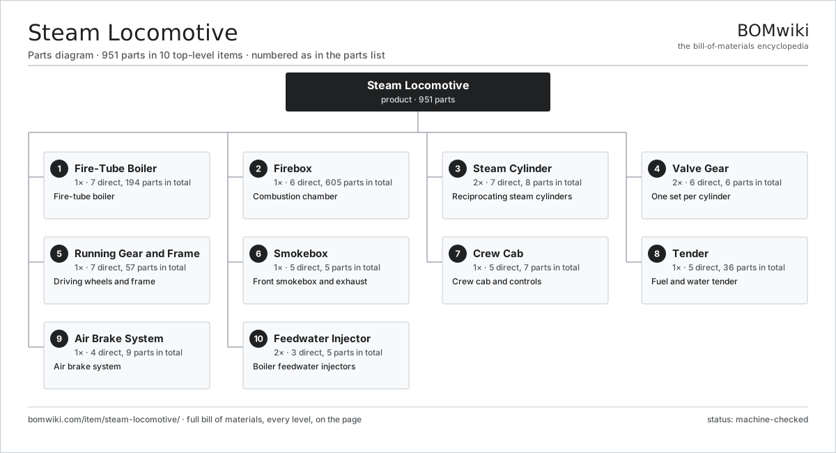
| # | Part | Qty | What it does |
|---|---|---|---|
| 1 | Fire-Tube Boiler 7 parts | 1× | Fire-tube boiler |
| 2 | Firebox 6 parts | 1× | Combustion chamber |
| 3 | Steam Cylinder 7 parts | 2× | Reciprocating steam cylinders |
| 4 | Valve Gear 6 parts | 2× | One set per cylinder |
| 5 | Running Gear and Frame 7 parts | 1× | Driving wheels and frame |
| 6 | Smokebox 5 parts | 1× | Front smokebox and exhaust |
| 7 | Crew Cab 5 parts | 1× | Crew cab and controls |
| 8 | Tender 5 parts | 1× | Fuel and water tender |
| 9 | Air Brake System 4 parts | 1× | Air brake system |
| 10 | Feedwater Injector 3 parts | 2× | Boiler feedwater injectors |
3D model
No 3D model yet. Have a CAD file of this? Add a 3D model. STL renders right on this page; STEP, FreeCAD, and OpenSCAD sources are welcome too (openly licensed, like all 3D models on BOMwiki).
Build & assembly graph
expand / collapse · shared sub-assemblies converge · links to related products · est. labourTap an assembly to expand/collapse · tap a part to open it · use “Open page” for any node · drag to pan, scroll to zoom.
Bill of materials for Steam Locomotive
10 top-level lines · 83 rows shown · 951 parts total · indented to 3 levels| # | Item / sub-assembly | Part no. | Qty/assy | Ext. qty | Parts | Type |
|---|---|---|---|---|---|---|
| 1 | Fire-Tube Boiler 7 parts | steam-locomotive-boiler | 1× | 1 | 194 | assembly |
| 1.1 | Boiler Barrel | steam-locomotive-boiler-barrel | 1× | 1 | · | part |
| 1.2 | Fire Tube | steam-locomotive-fire-tube | 140× | 140 | · | part |
| 1.3 | Superheater Flue Tube | steam-locomotive-flue-tube | 24× | 24 | · | part |
| 1.4 | Superheater 2 parts | steam-locomotive-superheater | 1× | 1 | 25 | assembly |
| 1.4.1 | Superheater Element | steam-locomotive-superheater-element | 24× | 24 | · | part |
| 1.4.2 | Superheater Header | steam-locomotive-superheater-header | 1× | 1 | · | part |
| 1.5 | Regulator (Throttle) Valve | steam-locomotive-regulator | 1× | 1 | · | part |
| 1.6 | Safety Valve | steam-locomotive-safety-valve | 2× | 2 | · | part |
| 1.7 | Steam Dome | steam-locomotive-dome | 1× | 1 | · | part |
| 2 | Firebox 6 parts | steam-locomotive-firebox | 1× | 1 | 605 | assembly |
| 2.1 | Inner Firebox | steam-locomotive-inner-firebox | 1× | 1 | · | part |
| 2.2 | Outer Firebox Wrapper | steam-locomotive-outer-firebox | 1× | 1 | · | part |
| 2.3 | Firebox Stay | steam-locomotive-firebox-stay | 600× | 600 | · | part |
| 2.4 | Firegrate | steam-locomotive-grate | 1× | 1 | · | part |
| 2.5 | Firehole Door | steam-locomotive-firedoor | 1× | 1 | · | part |
| 2.6 | Brick Arch | steam-locomotive-brick-arch | 1× | 1 | · | part |
| 3 | Steam Cylinder 7 parts | steam-locomotive-cylinder | 2× | 2 | 8 | assembly |
| 3.1 | Cylinder Block | steam-locomotive-cylinder-block | 1× | 2 | · | part |
| 3.2 | Piston and Rings | steam-locomotive-piston | 1× | 2 | · | part |
| 3.3 | Piston Rod | steam-locomotive-piston-rod | 1× | 2 | · | part |
| 3.4 | Crosshead | steam-locomotive-crosshead | 1× | 2 | · | part |
| 3.5 | Piston Valve | steam-locomotive-piston-valve | 1× | 2 | · | part |
| 3.6 | Cylinder Drain Cock | steam-locomotive-cylinder-cock | 2× | 4 | · | part |
| 3.7 | O-Ring Set | oring-set | 1× | 2 | · | part |
| 4 | Valve Gear 6 parts | steam-locomotive-valve-gear | 2× | 2 | 6 | assembly |
| 4.1 | Eccentric Crank | steam-locomotive-eccentric-crank | 1× | 2 | · | part |
| 4.2 | Expansion Link | steam-locomotive-expansion-link | 1× | 2 | · | part |
| 4.3 | Radius Rod | steam-locomotive-radius-rod | 1× | 2 | · | part |
| 4.4 | Combination Lever | steam-locomotive-combination-lever | 1× | 2 | · | part |
| 4.5 | Valve Spindle | steam-locomotive-valve-spindle | 1× | 2 | · | part |
| 4.6 | Reversing Gear | steam-locomotive-reverser | 1× | 2 | · | part |
| 5 | Running Gear and Frame 7 parts | steam-locomotive-running-gear | 1× | 1 | 57 | assembly |
| 5.1 | Main Frame | steam-locomotive-main-frame | 1× | 1 | · | part |
| 5.2 | Driving Wheelset 4 parts | steam-locomotive-driving-wheel | 4× | 4 | 7 | assembly |
| 5.2.1 | Wheel Center | steam-locomotive-wheel-center | 2× | 8 | · | part |
| 5.2.2 | Steel Tire | steam-locomotive-tire | 2× | 8 | · | part |
| 5.2.3 | Driving Axle | steam-locomotive-crank-axle | 1× | 4 | · | part |
| 5.2.4 | Wheel Counterweight | steam-locomotive-counterweight | 2× | 8 | · | part |
| 5.3 | Main Connecting Rod | steam-locomotive-connecting-rod | 2× | 2 | · | part |
| 5.4 | Coupling Rod | steam-locomotive-coupling-rod | 2× | 2 | · | part |
| 5.5 | Leading Truck (Pony Truck) 3 parts | steam-locomotive-leading-truck | 1× | 1 | 8 | assembly |
| 5.5.1 | Carrying Truck Wheel | steam-locomotive-truck-wheel | 2× | 2 | · | part |
| 5.5.2 | Coil Spring | coil-spring | 4× | 4 | · | part |
| 5.5.3 | Axle Bearing (Driving Box) | steam-locomotive-axle-bearing | 2× | 2 | · | part |
| 5.6 | Trailing Truck 3 parts | steam-locomotive-trailing-truck | 1× | 1 | 8 | assembly |
| 5.6.1 | Carrying Truck Wheel | steam-locomotive-truck-wheel | 2× | 2 | · | part |
| 5.6.2 | Coil Spring | coil-spring | 4× | 4 | · | part |
| 5.6.3 | Axle Bearing (Driving Box) | steam-locomotive-axle-bearing | 2× | 2 | · | part |
| 5.7 | Axle Bearing (Driving Box) | steam-locomotive-axle-bearing | 8× | 8 | · | part |
| 6 | Smokebox 5 parts | steam-locomotive-smokebox | 1× | 1 | 5 | assembly |
| 6.1 | Smokebox Shell | steam-locomotive-smokebox-shell | 1× | 1 | · | part |
| 6.2 | Blastpipe | steam-locomotive-blastpipe | 1× | 1 | · | part |
| 6.3 | Chimney | steam-locomotive-chimney | 1× | 1 | · | part |
| 6.4 | Spark Arrestor | steam-locomotive-spark-arrestor | 1× | 1 | · | part |
| 6.5 | Smokebox Door | steam-locomotive-smokebox-door | 1× | 1 | · | part |
| 7 | Crew Cab 5 parts | steam-locomotive-cab | 1× | 1 | 7 | assembly |
| 7.1 | Cab Shell | steam-locomotive-cab-shell | 1× | 1 | · | part |
| 7.2 | Boiler Pressure Gauge | steam-locomotive-pressure-gauge | 2× | 2 | · | part |
| 7.3 | Water Level Gauge | steam-locomotive-water-gauge | 2× | 2 | · | part |
| 7.4 | Steam Whistle | steam-locomotive-whistle | 1× | 1 | · | part |
| 7.5 | Mechanical Lubricator | steam-locomotive-lubricator | 1× | 1 | · | part |
| 8 | Tender 5 parts | steam-locomotive-tender | 1× | 1 | 36 | assembly |
| 8.1 | Tender Frame | steam-locomotive-tender-frame | 1× | 1 | · | part |
| 8.2 | Water Tank | steam-locomotive-water-tank | 1× | 1 | · | part |
| 8.3 | Coal Bunker | steam-locomotive-coal-bunker | 1× | 1 | · | part |
| 8.4 | Tender Truck 3 parts | steam-locomotive-tender-truck | 2× | 2 | 16 | assembly |
| 8.4.1 | Carrying Truck Wheel | steam-locomotive-truck-wheel | 4× | 8 | · | part |
| 8.4.2 | Coil Spring | coil-spring | 8× | 16 | · | part |
| 8.4.3 | Axle Bearing (Driving Box) | steam-locomotive-axle-bearing | 4× | 8 | · | part |
| 8.5 | Coupler and Drawbar | steam-locomotive-coupler | 1× | 1 | · | part |
| 9 | Air Brake System 4 parts | steam-locomotive-brake-system | 1× | 1 | 9 | assembly |
| 9.1 | Steam Air Pump 3 parts | steam-locomotive-air-pump | 1× | 1 | 4 | assembly |
| 9.1.1 | Steam Drive Piston | steam-locomotive-steam-piston | 1× | 1 | · | part |
| 9.1.2 | Air Compression Piston | steam-locomotive-air-piston | 1× | 1 | · | part |
| 9.1.3 | O-Ring Set | oring-set | 2× | 2 | · | part |
| 9.2 | Air Reservoir | steam-locomotive-air-reservoir | 2× | 2 | · | part |
| 9.3 | Engineer Brake Valve | steam-locomotive-brake-valve | 1× | 1 | · | part |
| 9.4 | Brake Cylinder | steam-locomotive-brake-cylinder | 2× | 2 | · | part |
| 10 | Feedwater Injector 3 parts | steam-locomotive-injector | 2× | 2 | 5 | assembly |
| 10.1 | Injector Cone | steam-locomotive-injector-cone | 3× | 6 | · | part |
| 10.2 | Injector Body | steam-locomotive-injector-body | 1× | 2 | · | part |
| 10.3 | Boiler Check Valve (Clack) | steam-locomotive-check-valve | 1× | 2 | · | part |
Related products
same domain, ranked by shared parts Airport Apron Bus
759 parts · shares 1 with this page
Airport Apron Bus
759 parts · shares 1 with this page
 Auto-Rack Railcar
522 parts · shares 1 with this page
Auto-Rack Railcar
522 parts · shares 1 with this page
 Automated People Mover
450 parts · shares 1 with this page
Autorack Wagon
217 parts · shares 1 with this page
Automated People Mover
450 parts · shares 1 with this page
Autorack Wagon
217 parts · shares 1 with this page
 Ballast Regulator
234 parts · shares 1 with this page
Ballast Regulator
234 parts · shares 1 with this page
 Boxcar
256 parts · shares 1 with this page
Boxcar
256 parts · shares 1 with this page
Sourcing: possible vendors
Browse the supplier directory → Prices, MOQ, and lead times are algorithmic estimates, not quotes, and not claims about these companies. Company mappings are curated by keyword; est. price band $500k–$60M. How estimates work| Vendor | HQ | Specialty | MOQ | Lead time |
|---|---|---|---|---|
|
🇨🇳CRRC
crrcgc.cc ↗
|
Beijing, CN | Rolling stock & rail systems | made to order | 40–72 wks |
|
🇫🇷Alstom
alstom.com ↗
|
Saint-Ouen, FR | Rail rolling stock | made to order | 40–72 wks |
| mobility.siemens.com ↗ | Munich, DE | Rail systems | made to order | 40–72 wks |
| stadlerrail.com ↗ | Bussnang, CH | Rail rolling stock | made to order | 40–72 wks |
|
🇺🇸Wabtec
wabteccorp.com ↗
|
Pittsburgh, US | Rail equipment | made to order | 40–72 wks |
1,053-word article