Continuous Inkjet Coder
ProductOverview
A continuous inkjet coder marks variable information, such as expiry dates, lot numbers, and barcodes, onto products and packaging as they move past on a line. Unlike a drop-on-demand printer that fires ink only where a mark is needed, a continuous inkjet coder runs an unbroken stream of ink the whole time it is switched on. The stream is broken into a steady train of identical drops, each drop is given a controlled electrical charge, and the charged drops are steered by a high-voltage field to land where the character needs ink. Drops that are not needed stay uncharged, fly straight, and are caught and recycled. This design lets the coder mark non-contact at high line speed onto almost any surface, including curved bottles, cartons, cables, and pipe, from a small distance away.
The machine has six working sections. The Printhead forms and aims the drops, the Ink System keeps ink at the right pressure and viscosity, the Electronics Cabinet holds the electronics and high-voltage supply, the Controller and HMI is the operator screen, the Fluid Supply Bay holds the consumable cartridges, and the Line Interface reads the line so prints land in the right place.
How a drop becomes a character
Ink leaves the Nozzle as a fine jet around 60 microns across. The Drop Generator Crystal vibrates the nozzle at a fixed frequency, and that vibration makes the jet break into a regular train of equal-sized drops at a known point in space. As each drop pinches off, it passes through the Charge Electrode, which applies the exact charge that drop needs. Charged drops then pass between the Deflection Plate, where a strong field bends their path by an amount that depends on their charge, so a single nozzle can place ink across the full height of a character by varying charge from drop to drop. Drops left uncharged fly straight into the Gutter and return to the tank. A Phase Detector watches the break-off and feeds back to keep the charge applied at exactly the right instant, since drift in break-off timing would smear the print.
Ink, solvent, and recirculation
Because the head runs continuously, ink management is the heart of the machine. The Ink Pump supplies ink to the nozzle at a steady pressure near 3 bar, set by a Pressure Sensor in the line. Recovered ink from the gutter, fresh ink from the cartridge, and make-up solvent all blend in the Mixer Tank. Solvent matters because the inks are volatile, MEK or ethanol based, and they evaporate from the exposed jet, which thickens the ink. A Viscometer reads viscosity and the system doses solvent through the Solenoid Valve set to hold it constant, since drop size and flight depend on a stable viscosity. Multiple Ink Filter stages protect the tiny nozzle from any particle that would clog it, and the whole circuit ports through a machined Fluid Manifold.
Electronics and timing
The print quality depends on timing drops to within a fraction of a microsecond. The Main Board rasterizes the message and the Timing FPGA on it generates the per-drop charge pattern in lockstep with break-off. That pattern is amplified by the Charge Driver Board to swing the charge electrode, while the HV Supply holds the deflection plates at a stable few kilovolts. The I/O Board brings in the product sensor and encoder signals and drives line outputs. All of this sits in a sealed Electronics Cabinet kept cool by a filtered Cabinet Fan, because the cabinet must stay closed against the solvent-laden, dusty packaging-line air.
Operating on a line
A coder is only useful if it prints in the right spot on a moving product. The Product Sensor detects each package edge and triggers a print, and the Shaft Encoder reports line speed so the printed width stays correct whether the line runs fast or slow. The Controller and HMI lets the operator build the message, including live date and counter fields and barcodes, on its LCD Panel touchscreen. Consumables load through the Fluid Supply Bay, where a Cartridge ID Reader checks each cartridge type and expiry and Level Sensor units warn before a cartridge runs dry. The whole unit mounts on a stainless Stand and Enclosure so it can be washed down between shifts.
Variants and use
Continuous inkjet is chosen where speed and non-contact marking matter more than high resolution. It codes glass and PET bottles on beverage lines, marks lot and date on flexible film and cartons, prints gauge marks and part numbers on extruded cable and pipe, and codes eggs and produce. Pigmented white inks code dark surfaces such as wire and rubber, while contrast inks and UV-readable inks suit security and traceability. Where a wider, higher-resolution mark is needed, a line may use a thermal inkjet or a laser coder instead, but those trade away the ink flexibility and throw distance that continuous inkjet provides. The main running cost and maintenance task is fluid: keeping the Nozzle clean, the Viscometer reading true, and the cartridges fresh is what keeps a coder printing crisp marks shift after shift.
Continuous Inkjet Coder parts and their functions
7 top-level parts · 501 parts in total · full bill of materials below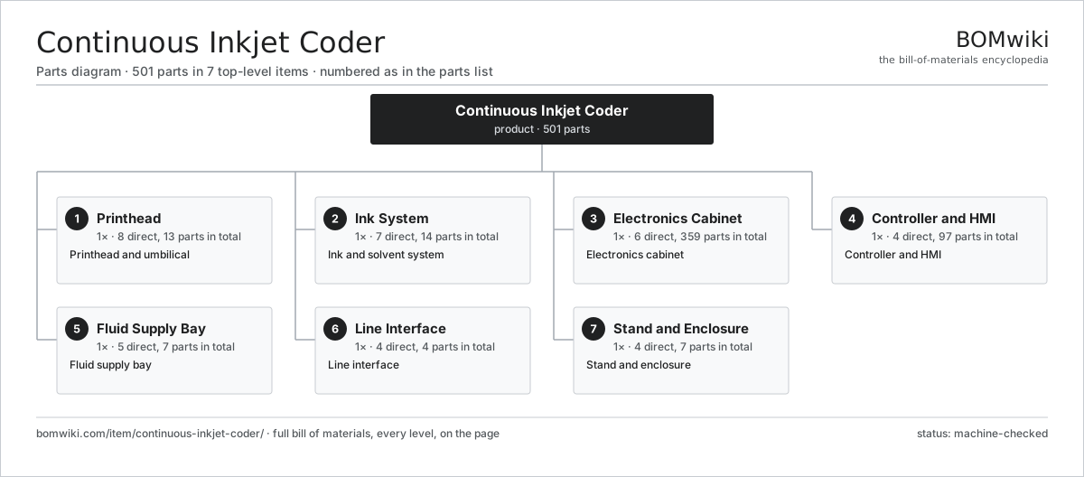
| # | Part | Qty | What it does |
|---|---|---|---|
| 1 | Printhead 8 parts | 1× | Printhead and umbilical |
| 2 | Ink System 7 parts | 1× | Ink and solvent system |
| 3 | Electronics Cabinet 6 parts | 1× | Electronics cabinet |
| 4 | Controller and HMI 4 parts | 1× | Controller and HMI |
| 5 | Fluid Supply Bay 5 parts | 1× | Fluid supply bay |
| 6 | Line Interface 4 parts | 1× | Line interface |
| 7 | Stand and Enclosure 4 parts | 1× | Stand and enclosure |
3D model
No 3D model yet. Have a CAD file of this? Add a 3D model. STL renders right on this page; STEP, FreeCAD, and OpenSCAD sources are welcome too (openly licensed, like all 3D models on BOMwiki).
Build & assembly graph
expand / collapse · shared sub-assemblies converge · links to related products · est. labourTap an assembly to expand/collapse · tap a part to open it · use “Open page” for any node · drag to pan, scroll to zoom.
Bill of materials for Continuous Inkjet Coder
7 top-level lines · 67 rows shown · 501 parts total · indented to 3 levels| # | Item / sub-assembly | Part no. | Qty/assy | Ext. qty | Parts | Type |
|---|---|---|---|---|---|---|
| 1 | Printhead 8 parts | continuous-inkjet-coder-printhead | 1× | 1 | 13 | assembly |
| 1.1 | Nozzle | continuous-inkjet-coder-nozzle | 1× | 1 | · | part |
| 1.2 | Drop Generator Crystal 2 parts | continuous-inkjet-coder-piezo-driver | 1× | 1 | 2 | assembly |
| 1.2.1 | Piezoelectric Element | piezo-element | 1× | 1 | · | part |
| 1.2.2 | Crystal Mount | continuous-inkjet-coder-crystal-mount | 1× | 1 | · | part |
| 1.3 | Charge Electrode | continuous-inkjet-coder-charge-electrode | 1× | 1 | · | part |
| 1.4 | Deflection Plate | continuous-inkjet-coder-deflection-plates | 2× | 2 | · | part |
| 1.5 | Gutter | continuous-inkjet-coder-gutter | 1× | 1 | · | part |
| 1.6 | Phase Detector | continuous-inkjet-coder-phase-detector | 1× | 1 | · | part |
| 1.7 | Head Cover | continuous-inkjet-coder-head-cover | 1× | 1 | · | part |
| 1.8 | Umbilical 3 parts | continuous-inkjet-coder-umbilical | 1× | 1 | 4 | assembly |
| 1.8.1 | Ink Tube | continuous-inkjet-coder-ink-tube | 2× | 2 | · | part |
| 1.8.2 | Wire Bundle | wire-bundle | 1× | 1 | · | part |
| 1.8.3 | HV Cable | continuous-inkjet-coder-hv-cable | 1× | 1 | · | part |
| 2 | Ink System 7 parts | continuous-inkjet-coder-ink-system | 1× | 1 | 14 | assembly |
| 2.1 | Ink Pump 3 parts | continuous-inkjet-coder-ink-pump | 1× | 1 | 3 | assembly |
| 2.1.1 | Pump Motor | continuous-inkjet-coder-pump-motor | 1× | 1 | · | part |
| 2.1.2 | Pump Head | continuous-inkjet-coder-pump-head | 1× | 1 | · | part |
| 2.1.3 | O-Ring Set | oring-set | 1× | 1 | · | part |
| 2.2 | Mixer Tank | continuous-inkjet-coder-ink-tank | 1× | 1 | · | part |
| 2.3 | Viscometer | continuous-inkjet-coder-viscometer | 1× | 1 | · | part |
| 2.4 | Ink Filter | continuous-inkjet-coder-ink-filter | 3× | 3 | · | part |
| 2.5 | Solenoid Valve | continuous-inkjet-coder-solvent-valve | 4× | 4 | · | part |
| 2.6 | Pressure Sensor | pressure-sensor | 1× | 1 | · | part |
| 2.7 | Fluid Manifold | continuous-inkjet-coder-manifold | 1× | 1 | · | part |
| 3 | Electronics Cabinet 6 parts | continuous-inkjet-coder-cabinet | 1× | 1 | 359 | assembly |
| 3.1 | Main Board 4 parts | continuous-inkjet-coder-main-board | 1× | 1 | 203 | assembly |
| 3.1.1 | Bare PCB | pcb-bare | 1× | 1 | · | part |
| 3.1.2 | Microcontroller | mcu | 1× | 1 | · | part |
| 3.1.3 | Timing FPGA | continuous-inkjet-coder-fpga | 1× | 1 | · | part |
| 3.1.4 | SMD Passive (R/C/L) | smd-passives | 200× | 200 | · | part |
| 3.2 | HV Supply | continuous-inkjet-coder-hv-supply | 1× | 1 | · | part |
| 3.3 | Power Supply | power-supply | 1× | 1 | · | part |
| 3.4 | Charge Driver Board 3 parts | continuous-inkjet-coder-driver-board | 1× | 1 | 82 | assembly |
| 3.4.1 | Bare PCB | pcb-bare | 1× | 1 | · | part |
| 3.4.2 | HV Amplifier | continuous-inkjet-coder-hv-amp | 1× | 1 | · | part |
| 3.4.3 | SMD Passive (R/C/L) | smd-passives | 80× | 80 | · | part |
| 3.5 | I/O Board 4 parts | continuous-inkjet-coder-io-board | 1× | 1 | 71 | assembly |
| 3.5.1 | Bare PCB | pcb-bare | 1× | 1 | · | part |
| 3.5.2 | Connector | connector | 8× | 8 | · | part |
| 3.5.3 | Relay | relay | 2× | 2 | · | part |
| 3.5.4 | SMD Passive (R/C/L) | smd-passives | 60× | 60 | · | part |
| 3.6 | Cabinet Fan | continuous-inkjet-coder-cooling-fan | 1× | 1 | · | part |
| 4 | Controller and HMI 4 parts | continuous-inkjet-coder-controller | 1× | 1 | 97 | assembly |
| 4.1 | LCD Panel | lcd-panel | 1× | 1 | · | part |
| 4.2 | Touch Controller Board 3 parts | continuous-inkjet-coder-touch-board | 1× | 1 | 92 | assembly |
| 4.2.1 | Bare PCB | pcb-bare | 1× | 1 | · | part |
| 4.2.2 | Microcontroller | mcu | 1× | 1 | · | part |
| 4.2.3 | SMD Passive (R/C/L) | smd-passives | 90× | 90 | · | part |
| 4.3 | Sealed Bezel | continuous-inkjet-coder-bezel | 1× | 1 | · | part |
| 4.4 | Connector | connector | 3× | 3 | · | part |
| 5 | Fluid Supply Bay 5 parts | continuous-inkjet-coder-fluid-supply | 1× | 1 | 7 | assembly |
| 5.1 | Ink Cartridge | continuous-inkjet-coder-ink-cartridge | 1× | 1 | · | part |
| 5.2 | Solvent Cartridge | continuous-inkjet-coder-solvent-cartridge | 1× | 1 | · | part |
| 5.3 | Cartridge Dock | continuous-inkjet-coder-cartridge-dock | 2× | 2 | · | part |
| 5.4 | Level Sensor | continuous-inkjet-coder-level-sensor | 2× | 2 | · | part |
| 5.5 | Cartridge ID Reader | continuous-inkjet-coder-rfid-reader | 1× | 1 | · | part |
| 6 | Line Interface 4 parts | continuous-inkjet-coder-conveyor-interface | 1× | 1 | 4 | assembly |
| 6.1 | Product Sensor | continuous-inkjet-coder-product-sensor | 1× | 1 | · | part |
| 6.2 | Shaft Encoder | continuous-inkjet-coder-shaft-encoder | 1× | 1 | · | part |
| 6.3 | Sensor Bracket | continuous-inkjet-coder-sensor-bracket | 1× | 1 | · | part |
| 6.4 | Wire Bundle | wire-bundle | 1× | 1 | · | part |
| 7 | Stand and Enclosure 4 parts | continuous-inkjet-coder-frame | 1× | 1 | 7 | assembly |
| 7.1 | Floor Stand | continuous-inkjet-coder-stand | 1× | 1 | · | part |
| 7.2 | Head Bracket | continuous-inkjet-coder-head-bracket | 1× | 1 | · | part |
| 7.3 | Sheet Metal Panel | sheet-panel | 4× | 4 | · | part |
| 7.4 | Fastener Set | fastener-set | 1× | 1 | · | part |
Related products
same domain, ranked by shared parts Date Coding Machine
62 parts · shares 3 with this page
Date Coding Machine
62 parts · shares 3 with this page
 Aerosol Filling Machine
119 parts · shares 3 with this page
Aerosol Filling Machine
119 parts · shares 3 with this page
 Automatic Strapping Machine
251 parts · shares 3 with this page
Automatic Strapping Machine
251 parts · shares 3 with this page
 Digital Inkjet Web Press
3,001 parts · shares 3 with this page
Gravity Filling Machine
177 parts · shares 3 with this page
Digital Inkjet Web Press
3,001 parts · shares 3 with this page
Gravity Filling Machine
177 parts · shares 3 with this page
 Industrial Screen Printing Press
162 parts · shares 3 with this page
Industrial Screen Printing Press
162 parts · shares 3 with this page
Sourcing: possible vendors
Browse the supplier directory → Prices, MOQ, and lead times are algorithmic estimates, not quotes, and not claims about these companies. Company mappings are curated by keyword; est. price band $10k–$3M. How estimates work| Vendor | HQ | Specialty | MOQ | Lead time |
|---|---|---|---|---|
| heidelberg.com ↗ | Heidelberg, DE | Printing presses | 10 units | 12–22 wks |
|
🇨🇭Bobst
bobst.com ↗
|
Lausanne, CH | Packaging machinery | 10 units | 12–22 wks |
| koenig-bauer.com ↗ | Würzburg, DE | Printing presses | 10 units | 12–22 wks |
| wuh-group.com ↗ | Lengerich, DE | Flexible packaging machines | 10 units | 12–22 wks |
| markandy.com ↗ | Chesterfield, US | Label presses | 10 units | 12–22 wks |
952-word article