Paper Banding Machine
ProductOverview
A paper banding machine wraps a narrow band of paper or film around a group of products and seals the band into a closed loop. The band holds items together without glue, staples or shrink film, and it leaves a clean printable surface for branding or product information. Banders are used for currency and document bundles, printed matter, produce, bakery items, cosmetics, hardware kits and any set of products that ship as a unit. Throughput runs from 20 to 40 bands per minute depending on band length and the size of the stack. The machine in this entry is an arch-type bander: the band is formed into an open loop inside a guide arch, the loop is dropped around the product, tightened, sealed and cut.
How a banding cycle works
The cycle starts when the Product Sensor confirms a product is sitting on the Table Top inside the arch opening. The Feed Roller Set pulls band off the reel and pushes the leading edge into the Band Guide Arch. Inside the arch, the Loop Former carries the band edge all the way around the channel until the band has formed a complete open loop surrounding the work zone. The Arch Gate then opens and the Tensioning Unit retracts the band, pulling the loop off the arch channel and down onto the product. As the band tightens, the Press Plate holds the stack square. Once the Tension Sensor reads the target tension, the Seal Jaw clamps the band overlap, fuses it, and the Band Cutter severs the band. The banded product is then released.
Band reel and feed
The band is supplied as a wound coil. The Band Reel sits on the Reel Holder, whose Reel Brake applies friction so the coil does not overrun when feed stops. Between the reel and the feed nip, the Dancer Arm rides on a slack loop of band. The Dancer Potentiometer reads the arm angle, and the controller uses that signal to keep the buffer loop within range so the band never goes taut against the reel brake during a fast feed. The Feed Roller Set meters band length: a knurled Drive Roller driven by the Feed Motor grips the band against a spring-loaded Pinch Roller. Band length per cycle is set from the HMI and counted in stepper steps, so the loop length matches the product girth with little waste. The Band Detect Sensor flags a run-out so the operator can splice a new coil before the machine jams.
Arch and loop forming
The Arch Assembly is the part that turns a flat band into a loop without an operator threading it by hand. The Band Guide Arch is a U-channel built from two Arch Channel rails and a clear Arch Window so the band path stays visible. The Loop Former uses a narrow Loop Belt running on small pulleys to carry the band leading edge around the channel. When the loop is complete, the leading edge meets the trailing band near the seal head, and the Arch Gate releases the loop so tension can collapse it onto the product. Arch openings range from about 180 mm square for small bundles up to 300 by 250 mm for larger stacks.
Tensioning and sealing
The Tensioning Unit sets how tight the band sits on the product. A Tension Roller driven by a Tension Motor retracts band while the Tension Sensor measures force, so the controller can hold a target between roughly 5 and 60 N. Light tension suits soft or printed goods that mark easily; high tension keeps a heavy stack from slipping. The Sealing Unit then bonds the overlap. The Seal Jaw carries a Heating Element behind a PTFE-coated Seal Platen, and a Temperature Sensor holds the set point, usually 120 to 180 °C for paper and OPP film. The Seal Actuator presses the platen against the Seal Anvil for a set dwell, the bond cools under the Cooling Fan, and the Band Cutter trims the band square. Heat sealing needs band stock with a heat-activated coating or a film layer; uncoated paper is sealed with an adhesive tab or run on ultrasonic seal heads instead.
Materials and band choice
Band stock is chosen for strength, print quality and seal behaviour. Paper bands, often kraft or printed coated paper from 0.06 to 0.12 mm, give a matte printable surface and tear cleanly when the customer opens the bundle. OPP film bands are stronger, resist moisture and suit produce or chilled goods. Band width runs from 20 to 50 mm: narrow bands save material on small bundles, wider bands spread load on heavy stacks. Coil cores are typically 40 to 76 mm with outer diameters up to 200 mm, which sets how often an operator reloads. Printed bands carry barcodes, batch dates or branding, so the band does packaging and labelling in one pass.
Control, drive and safety
The Control System runs the sequence. A PLC Module times feed, loop forming, tension and seal against the Main Drive and its Cam Shaft, while the Power Supply feeds logic and the heater driver. Operators set band length, tension, seal temperature and dwell from the HMI Panel, and the machine stores 20 to 50 recipes so a product change is a single selection. The Safety Relay holds the emergency stop circuit, and the Safety Guarding covers the hot seal head and the cutter, with an Interlock Switch stopping the cycle if a cover opens. Air at 5 to 6 bar drives the Seal Actuator and the Clamp Cylinder. A compact bander fits on a bench in under 0.8 m of length, which lets it sit at the end of a packing line or stand alone for batch work.
Paper Banding Machine parts and their functions
9 top-level parts · 173 parts in total · full bill of materials below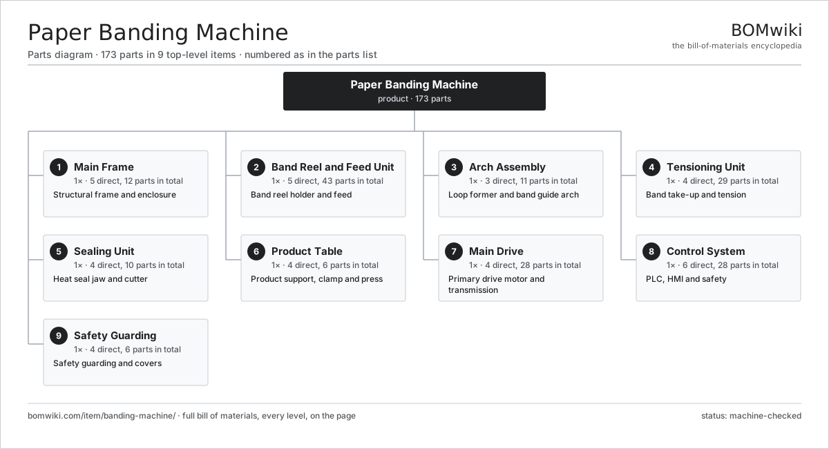
| # | Part | Qty | What it does |
|---|---|---|---|
| 1 | Main Frame 5 parts | 1× | Structural frame and enclosure |
| 2 | Band Reel and Feed Unit 5 parts | 1× | Band reel holder and feed |
| 3 | Arch Assembly 3 parts | 1× | Loop former and band guide arch |
| 4 | Tensioning Unit 4 parts | 1× | Band take-up and tension |
| 5 | Sealing Unit 4 parts | 1× | Heat seal jaw and cutter |
| 6 | Product Table 4 parts | 1× | Product support, clamp and press |
| 7 | Main Drive 4 parts | 1× | Primary drive motor and transmission |
| 8 | Control System 6 parts | 1× | PLC, HMI and safety |
| 9 | Safety Guarding 4 parts | 1× | Safety guarding and covers |
3D model
No 3D model yet. Have a CAD file of this? Add a 3D model. STL renders right on this page; STEP, FreeCAD, and OpenSCAD sources are welcome too (openly licensed, like all 3D models on BOMwiki).
Build & assembly graph
expand / collapse · shared sub-assemblies converge · links to related products · est. labourTap an assembly to expand/collapse · tap a part to open it · use “Open page” for any node · drag to pan, scroll to zoom.
Bill of materials for Paper Banding Machine
9 top-level lines · 94 rows shown · 173 parts total · indented to 3 levels| # | Item / sub-assembly | Part no. | Qty/assy | Ext. qty | Parts | Type |
|---|---|---|---|---|---|---|
| 1 | Main Frame 5 parts | banding-machine-main-frame | 1× | 1 | 12 | assembly |
| 1.1 | Frame Weldment | banding-machine-frame-weldment | 1× | 1 | · | part |
| 1.2 | Frame Column | banding-machine-column | 2× | 2 | · | part |
| 1.3 | Sheet Metal Panel | sheet-panel | 4× | 4 | · | part |
| 1.4 | Leveling Foot | banding-machine-leveling-foot | 4× | 4 | · | part |
| 1.5 | Fastener Set | fastener-set | 1× | 1 | · | part |
| 2 | Band Reel and Feed Unit 5 parts | banding-machine-reel-feed-unit | 1× | 1 | 43 | assembly |
| 2.1 | Reel Holder 3 parts | banding-machine-reel-holder | 1× | 1 | 4 | assembly |
| 2.1.1 | Reel Spindle | banding-machine-reel-spindle | 1× | 1 | · | part |
| 2.1.2 | Reel Brake | banding-machine-reel-brake | 1× | 1 | · | part |
| 2.1.3 | Ball Bearing | ball-bearing | 2× | 2 | · | part |
| 2.2 | Band Reel | banding-machine-band-reel | 1× | 1 | · | part |
| 2.3 | Dancer Arm 4 parts | banding-machine-dancer-arm | 1× | 1 | 5 | assembly |
| 2.3.1 | Dancer Roller | banding-machine-dancer-roller | 1× | 1 | · | part |
| 2.3.2 | Coil Spring | coil-spring | 1× | 1 | · | part |
| 2.3.3 | Dancer Potentiometer | banding-machine-dancer-potentiometer | 1× | 1 | · | part |
| 2.3.4 | Ball Bearing | ball-bearing | 2× | 2 | · | part |
| 2.4 | Feed Roller Set 5 parts | banding-machine-feed-roller-set | 1× | 1 | 32 | assembly |
| 2.4.1 | Drive Roller | banding-machine-drive-roller | 1× | 1 | · | part |
| 2.4.2 | Pinch Roller | banding-machine-pinch-roller | 1× | 1 | · | part |
| 2.4.3 | Feed Motor 3 parts + deeper › | banding-machine-feed-motor | 1× | 1 | 24 | assembly |
| 2.4.4 | Ball Bearing | ball-bearing | 4× | 4 | · | part |
| 2.4.5 | Coil Spring | coil-spring | 2× | 2 | · | part |
| 2.5 | Band Detect Sensor | banding-machine-band-detect-sensor | 1× | 1 | · | part |
| 3 | Arch Assembly 3 parts | banding-machine-arch-assembly | 1× | 1 | 11 | assembly |
| 3.1 | Loop Former 3 parts | banding-machine-loop-former | 1× | 1 | 6 | assembly |
| 3.1.1 | Loop Belt | banding-machine-loop-belt | 1× | 1 | · | part |
| 3.1.2 | Drive Belt | drive-belt | 1× | 1 | · | part |
| 3.1.3 | Ball Bearing | ball-bearing | 4× | 4 | · | part |
| 3.2 | Band Guide Arch 3 parts | banding-machine-band-guide-arch | 1× | 1 | 4 | assembly |
| 3.2.1 | Arch Channel | banding-machine-arch-channel | 2× | 2 | · | part |
| 3.2.2 | Arch Window | banding-machine-arch-window | 1× | 1 | · | part |
| 3.2.3 | Fastener Set | fastener-set | 1× | 1 | · | part |
| 3.3 | Arch Gate | banding-machine-arch-gate | 1× | 1 | · | part |
| 4 | Tensioning Unit 4 parts | banding-machine-tensioning-unit | 1× | 1 | 29 | assembly |
| 4.1 | Tension Roller | banding-machine-tension-roller | 1× | 1 | · | part |
| 4.2 | Tension Motor 3 parts | banding-machine-tension-motor | 1× | 1 | 26 | assembly |
| 4.2.1 | Servo Motor 4 parts + deeper › | servo-motor | 1× | 1 | 24 | assembly |
| 4.2.2 | Gearbox Housing | gearbox-housing | 1× | 1 | · | part |
| 4.2.3 | Oil Seal | oil-seal | 1× | 1 | · | part |
| 4.3 | Tension Sensor | banding-machine-tension-sensor | 1× | 1 | · | part |
| 4.4 | Helical Gear Pair | gear-pair | 1× | 1 | · | part |
| 5 | Sealing Unit 4 parts | banding-machine-sealing-unit | 1× | 1 | 10 | assembly |
| 5.1 | Seal Jaw 4 parts | banding-machine-seal-jaw | 1× | 1 | 4 | assembly |
| 5.1.1 | Heating Element | heating-element | 1× | 1 | · | part |
| 5.1.2 | Seal Platen | banding-machine-seal-platen | 1× | 1 | · | part |
| 5.1.3 | Temperature Sensor | temperature-sensor | 1× | 1 | · | part |
| 5.1.4 | Seal Anvil | banding-machine-anvil | 1× | 1 | · | part |
| 5.2 | Band Cutter 3 parts | banding-machine-cutter | 1× | 1 | 3 | assembly |
| 5.2.1 | Cutter Blade | banding-machine-cutter-blade | 1× | 1 | · | part |
| 5.2.2 | Cutter Solenoid | banding-machine-cutter-solenoid | 1× | 1 | · | part |
| 5.2.3 | Coil Spring | coil-spring | 1× | 1 | · | part |
| 5.3 | Seal Actuator 2 parts | banding-machine-seal-actuator | 1× | 1 | 2 | assembly |
| 5.3.1 | Seal Cylinder | banding-machine-seal-cylinder | 1× | 1 | · | part |
| 5.3.2 | O-Ring Set | oring-set | 1× | 1 | · | part |
| 5.4 | Cooling Fan | banding-machine-cooling-fan | 1× | 1 | · | part |
| 6 | Product Table 4 parts | banding-machine-product-table | 1× | 1 | 6 | assembly |
| 6.1 | Table Top | banding-machine-table-top | 1× | 1 | · | part |
| 6.2 | Press Plate | banding-machine-press-plate | 1× | 1 | · | part |
| 6.3 | Clamp Cylinder 3 parts | banding-machine-clamp-cylinder | 1× | 1 | 3 | assembly |
| 6.3.1 | Clamp Piston | banding-machine-clamp-piston | 1× | 1 | · | part |
| 6.3.2 | O-Ring Set | oring-set | 1× | 1 | · | part |
| 6.3.3 | Coil Spring | coil-spring | 1× | 1 | · | part |
| 6.4 | Product Sensor | banding-machine-product-sensor | 1× | 1 | · | part |
| 7 | Main Drive 4 parts | banding-machine-main-drive | 1× | 1 | 28 | assembly |
| 7.1 | Drive Motor 3 parts | banding-machine-drive-motor | 1× | 1 | 24 | assembly |
| 7.1.1 | Stator Assembly 3 parts + deeper › | stator-assembly | 1× | 1 | 3 | assembly |
| 7.1.2 | Rotor Assembly 4 parts + deeper › | rotor-assembly | 1× | 1 | 19 | assembly |
| 7.1.3 | Ball Bearing | ball-bearing | 2× | 2 | · | part |
| 7.2 | Cam Shaft | banding-machine-cam-shaft | 1× | 1 | · | part |
| 7.3 | Helical Gear Pair | gear-pair | 1× | 1 | · | part |
| 7.4 | Drive Belt | drive-belt | 2× | 2 | · | part |
| 8 | Control System 6 parts | banding-machine-control-system | 1× | 1 | 28 | assembly |
| 8.1 | PLC Module 4 parts | banding-machine-plc-module | 1× | 1 | 11 | assembly |
| 8.1.1 | Microcontroller | mcu | 1× | 1 | · | part |
| 8.1.2 | Bare PCB | pcb-bare | 1× | 1 | · | part |
| 8.1.3 | SMD Passive (R/C/L) | smd-passives | 1× | 1 | · | part |
| 8.1.4 | Connector | connector | 8× | 8 | · | part |
| 8.2 | HMI Panel 4 parts | banding-machine-hmi-panel | 1× | 1 | 4 | assembly |
| 8.2.1 | LCD Panel | lcd-panel | 1× | 1 | · | part |
| 8.2.2 | Touch Digitizer | touch-digitizer | 1× | 1 | · | part |
| 8.2.3 | Bare PCB | pcb-bare | 1× | 1 | · | part |
| 8.2.4 | Microcontroller | mcu | 1× | 1 | · | part |
| 8.3 | Power Supply 2 parts | banding-machine-power-supply | 1× | 1 | 5 | assembly |
| 8.3.1 | Power Supply | power-supply | 1× | 1 | · | part |
| 8.3.2 | Connector | connector | 4× | 4 | · | part |
| 8.4 | Safety Relay | banding-machine-safety-relay | 1× | 1 | · | part |
| 8.5 | Relay | relay | 6× | 6 | · | part |
| 8.6 | Wire Bundle | wire-bundle | 1× | 1 | · | part |
| 9 | Safety Guarding 4 parts | banding-machine-guarding | 1× | 1 | 6 | assembly |
| 9.1 | Seal Cover | banding-machine-seal-cover | 1× | 1 | · | part |
| 9.2 | Arch Cover | banding-machine-arch-cover | 1× | 1 | · | part |
| 9.3 | Interlock Switch | banding-machine-interlock-switch | 2× | 2 | · | part |
| 9.4 | Sheet Metal Panel | sheet-panel | 2× | 2 | · | part |
Related products
same domain, ranked by shared parts Automatic Strapping Machine
251 parts · shares 11 with this page
Wraparound Case Packer
278 parts · shares 10 with this page
Tray Shrink Packer
386 parts · shares 10 with this page
Automatic Strapping Machine
251 parts · shares 11 with this page
Wraparound Case Packer
278 parts · shares 10 with this page
Tray Shrink Packer
386 parts · shares 10 with this page
 Industrial Screen Printing Press
162 parts · shares 9 with this page
Gravity Filling Machine
177 parts · shares 8 with this page
Counter-Pressure Filler
519 parts · shares 8 with this page
Industrial Screen Printing Press
162 parts · shares 9 with this page
Gravity Filling Machine
177 parts · shares 8 with this page
Counter-Pressure Filler
519 parts · shares 8 with this page
Sourcing: possible vendors
Browse the supplier directory → Prices, MOQ, and lead times are algorithmic estimates, not quotes, and not claims about these companies. Company mappings are curated by keyword; est. price band $10k–$3M. How estimates work| Vendor | HQ | Specialty | MOQ | Lead time |
|---|---|---|---|---|
| heidelberg.com ↗ | Heidelberg, DE | Printing presses | 10 units | 12–22 wks |
|
🇨🇭Bobst
bobst.com ↗
|
Lausanne, CH | Packaging machinery | 10 units | 12–22 wks |
| koenig-bauer.com ↗ | Würzburg, DE | Printing presses | 10 units | 12–22 wks |
| wuh-group.com ↗ | Lengerich, DE | Flexible packaging machines | 10 units | 12–22 wks |
| markandy.com ↗ | Chesterfield, US | Label presses | 10 units | 12–22 wks |
1,058-word article