Date Coding Machine
ProductOverview
A date coding machine prints best-before dates, batch numbers, times, and serial counters directly onto packaging as it moves down a production line. Nearly every food, drink, and pharmaceutical pack carries such a code by law, and the coder is the device that puts it there at line speed without touching the product. The most common type, and the one described here, is the continuous ink-jet coder: it forms a steady jet of ink, breaks it into tiny drops, charges and steers the drops with electric fields, and writes characters on the passing pack from a small distance. Because nothing touches the surface, it codes curved bottles, flexible film, and porous card equally well, and because the jet runs continuously it keeps up with fast lines.
The machine has a small Print Head aimed at the conveyor, a Ink and Solvent System and Controller Cabinet that feed and drive it through an Umbilical Conduit, a Conveyor Trigger that senses the pack, a Mounting Stand that holds the head, and a Power and Control section that ties it to the line.
How the print head works
The Print Head is where the marking happens, and it works on the continuous ink-jet principle. Pressurized ink leaves a fine Jet Nozzle as a fast jet, and a Drop-Break Piezo crystal vibrates the nozzle so the jet breaks into a stream of identical drops at a fixed rate. As each drop forms it passes the Charge Electrode, which puts a chosen amount of charge on it. The charged drops then fly between two Deflection Plate plates held at high voltage, which bend each drop to a precise vertical position so the stream paints a column of the character. Drops not used for printing get no charge, fly straight, and fall into the Return Gutter to be recycled. A Phase Detector watches where the jet breaks up so the charge always lands on the right drop, and the Piezoelectric Element crystal sets the break frequency.
Ink and solvent management
Continuous ink jet only stays reliable if the ink is kept at exactly the right viscosity, because the solvent in it evaporates fast. The Ink and Solvent System manages this. A Pressure Pump supplies the nozzle from a Mixer Tank, a Recovery Pump pulls unused ink back from the gutter, and a Viscometer measures the mix so the system adds make-up solvent from the Solvent Cartridge as it evaporates and fresh ink from the Ink Cartridge as it is consumed. Ink Filter filters protect the fine nozzle, and a Pressure Sensor holds supply pressure steady. Recycling the gutter ink is what makes the running cost low, since most of the ink the machine pumps never reaches the pack.
The controller cabinet
The electronics live in a sealed Controller Cabinet kept apart from the ink fumes. Its Main Control Board builds the dot pattern for each character and times the charge on every drop, a High-Voltage Supply generates the kilovolts across the deflection plates, and a Charge Board drives the per-drop charge waveform. The operator works through the Touchscreen Display, editing the message, choosing date and counter rules, and reading status. A Power Supply feeds the boards and a Cabinet Fan keeps the high-voltage section cool. The Sealed Enclosure is rated to keep dust and solvent vapor out so the electronics last in a packaging hall.
Linking head to cabinet and line
The head sits at the conveyor while the cabinet stands beside the line, joined by the Umbilical Conduit. That conduit carries the Ink Supply Line, the Return Line, and the Signal Cable for charge, deflection, and phase, all inside a flexible Conduit Sheath. The Conveyor Trigger tells the coder when to print and how fast the line runs: a Product Sensor photocell fires each print as a pack arrives, and a Shaft Encoder driven by an Encoder Wheel reports line speed so the characters stay the right width whether the conveyor is fast or slow.
Mounting and integration
The Mounting Stand holds the head square to the pack at the correct throw distance, since the deflection range sets how far the head can be from the surface. A Stand Column sets the height, a Head Bracket aims the head, and Position Clamp clamps lock the position. The Power and Control section ties the coder into the production line: a Mains Inlet feeds power, a Interface Board exchanges start, fault, and product-select signals with the line PLC, and a Message Store holds the saved code layouts so an operator recalls the right format per product.
Use and variants
Date coders run on almost every packaging line, printing the legal best-before and batch codes that let a product be traced and recalled. Continuous ink jet suits high-speed coding onto any substrate and at any angle, which is why it is the most common technology. For flat porous surfaces such as carton flaps, thermal ink-jet coders give crisper print with simpler upkeep; for printing variable text onto flexible film during the wrapping step itself, a Thermal Transfer Overprinter presses the code through a ribbon onto the moving web. Laser coders mark by burning the surface and need no ink at all, but ink jet remains the general-purpose choice because it codes nearly anything that passes its head.
Date Coding Machine parts and their functions
7 top-level parts · 62 parts in total · full bill of materials below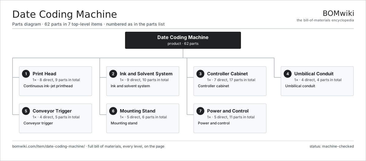
| # | Part | Qty | What it does |
|---|---|---|---|
| 1 | Print Head 8 parts | 1× | Continuous ink-jet printhead |
| 2 | Ink and Solvent System 9 parts | 1× | Ink and solvent system |
| 3 | Controller Cabinet 7 parts | 1× | Controller cabinet |
| 4 | Umbilical Conduit 4 parts | 1× | Umbilical conduit |
| 5 | Conveyor Trigger 4 parts | 1× | Conveyor trigger |
| 6 | Mounting Stand 5 parts | 1× | Mounting stand |
| 7 | Power and Control 5 parts | 1× | Power and control |
3D model
No 3D model yet. Have a CAD file of this? Add a 3D model. STL renders right on this page; STEP, FreeCAD, and OpenSCAD sources are welcome too (openly licensed, like all 3D models on BOMwiki).
Build & assembly graph
expand / collapse · shared sub-assemblies converge · links to related products · est. labourTap an assembly to expand/collapse · tap a part to open it · use “Open page” for any node · drag to pan, scroll to zoom.
Bill of materials for Date Coding Machine
7 top-level lines · 59 rows shown · 62 parts total · indented to 3 levels| # | Item / sub-assembly | Part no. | Qty/assy | Ext. qty | Parts | Type |
|---|---|---|---|---|---|---|
| 1 | Print Head 8 parts | date-coding-machine-printhead | 1× | 1 | 9 | assembly |
| 1.1 | Jet Nozzle | date-coding-machine-nozzle | 1× | 1 | · | part |
| 1.2 | Drop-Break Piezo | date-coding-machine-piezo | 1× | 1 | · | part |
| 1.3 | Charge Electrode | date-coding-machine-charge-electrode | 1× | 1 | · | part |
| 1.4 | Deflection Plate | date-coding-machine-deflection-plate | 2× | 2 | · | part |
| 1.5 | Return Gutter | date-coding-machine-gutter | 1× | 1 | · | part |
| 1.6 | Phase Detector | date-coding-machine-phase-detector | 1× | 1 | · | part |
| 1.7 | Head Cover | date-coding-machine-head-cover | 1× | 1 | · | part |
| 1.8 | Piezoelectric Element | piezo-element | 1× | 1 | · | part |
| 2 | Ink and Solvent System 9 parts | date-coding-machine-ink-system | 1× | 1 | 10 | assembly |
| 2.1 | Mixer Tank | date-coding-machine-ink-tank | 1× | 1 | · | part |
| 2.2 | Pressure Pump | date-coding-machine-ink-pump | 1× | 1 | · | part |
| 2.3 | Recovery Pump | date-coding-machine-recovery-pump | 1× | 1 | · | part |
| 2.4 | Ink Filter | date-coding-machine-ink-filter | 2× | 2 | · | part |
| 2.5 | Viscometer | date-coding-machine-viscometer | 1× | 1 | · | part |
| 2.6 | Ink Cartridge | date-coding-machine-ink-cartridge | 1× | 1 | · | part |
| 2.7 | Solvent Cartridge | date-coding-machine-solvent-cartridge | 1× | 1 | · | part |
| 2.8 | Pressure Sensor | pressure-sensor | 1× | 1 | · | part |
| 2.9 | O-Ring Set | oring-set | 1× | 1 | · | part |
| 3 | Controller Cabinet 7 parts | date-coding-machine-cabinet | 1× | 1 | 17 | assembly |
| 3.1 | Sealed Enclosure | date-coding-machine-enclosure | 1× | 1 | · | part |
| 3.2 | Main Control Board 4 parts | date-coding-machine-main-board | 1× | 1 | 9 | assembly |
| 3.2.1 | Bare PCB | pcb-bare | 1× | 1 | · | part |
| 3.2.2 | Microcontroller | mcu | 1× | 1 | · | part |
| 3.2.3 | SMD Passive (R/C/L) | smd-passives | 1× | 1 | · | part |
| 3.2.4 | Connector | connector | 6× | 6 | · | part |
| 3.3 | High-Voltage Supply | date-coding-machine-hv-supply | 1× | 1 | · | part |
| 3.4 | Charge Board | date-coding-machine-charge-board | 1× | 1 | · | part |
| 3.5 | Touchscreen Display 3 parts | date-coding-machine-display | 1× | 1 | 3 | assembly |
| 3.5.1 | LCD Panel | lcd-panel | 1× | 1 | · | part |
| 3.5.2 | Bare PCB | pcb-bare | 1× | 1 | · | part |
| 3.5.3 | Microcontroller | mcu | 1× | 1 | · | part |
| 3.6 | Power Supply | power-supply | 1× | 1 | · | part |
| 3.7 | Cabinet Fan | date-coding-machine-cooling-fan | 1× | 1 | · | part |
| 4 | Umbilical Conduit 4 parts | date-coding-machine-umbilical | 1× | 1 | 4 | assembly |
| 4.1 | Ink Supply Line | date-coding-machine-ink-line | 1× | 1 | · | part |
| 4.2 | Return Line | date-coding-machine-return-line | 1× | 1 | · | part |
| 4.3 | Signal Cable | date-coding-machine-signal-cable | 1× | 1 | · | part |
| 4.4 | Conduit Sheath | date-coding-machine-conduit-sheath | 1× | 1 | · | part |
| 5 | Conveyor Trigger 4 parts | date-coding-machine-conveyor-trigger | 1× | 1 | 5 | assembly |
| 5.1 | Product Sensor | date-coding-machine-product-sensor | 1× | 1 | · | part |
| 5.2 | Shaft Encoder | date-coding-machine-shaft-encoder | 1× | 1 | · | part |
| 5.3 | Encoder Wheel | date-coding-machine-encoder-wheel | 1× | 1 | · | part |
| 5.4 | Connector | connector | 2× | 2 | · | part |
| 6 | Mounting Stand 5 parts | date-coding-machine-stand | 1× | 1 | 6 | assembly |
| 6.1 | Stand Column | date-coding-machine-stand-column | 1× | 1 | · | part |
| 6.2 | Head Bracket | date-coding-machine-head-bracket | 1× | 1 | · | part |
| 6.3 | Position Clamp | date-coding-machine-clamp | 2× | 2 | · | part |
| 6.4 | Base Plate | date-coding-machine-base-plate | 1× | 1 | · | part |
| 6.5 | Fastener Set | fastener-set | 1× | 1 | · | part |
| 7 | Power and Control 5 parts | date-coding-machine-power | 1× | 1 | 11 | assembly |
| 7.1 | Mains Inlet | date-coding-machine-mains-inlet | 1× | 1 | · | part |
| 7.2 | Interface Board 3 parts | date-coding-machine-io-board | 1× | 1 | 6 | assembly |
| 7.2.1 | Bare PCB | pcb-bare | 1× | 1 | · | part |
| 7.2.2 | Microcontroller | mcu | 1× | 1 | · | part |
| 7.2.3 | Connector | connector | 4× | 4 | · | part |
| 7.3 | Message Store | date-coding-machine-message-store | 1× | 1 | · | part |
| 7.4 | Relay | relay | 2× | 2 | · | part |
| 7.5 | Wire Bundle | wire-bundle | 1× | 1 | · | part |
Related products
same domain, ranked by shared parts Continuous Inkjet Coder
501 parts · shares 3 with this page
Continuous Inkjet Coder
501 parts · shares 3 with this page
 Aerosol Filling Machine
119 parts · shares 2 with this page
Aerosol Filling Machine
119 parts · shares 2 with this page
 Automatic Strapping Machine
251 parts · shares 2 with this page
Case Labeling Machine
120 parts · shares 2 with this page
Channel Letter Bender
196 parts · shares 2 with this page
Counter-Pressure Filler
519 parts · shares 2 with this page
Automatic Strapping Machine
251 parts · shares 2 with this page
Case Labeling Machine
120 parts · shares 2 with this page
Channel Letter Bender
196 parts · shares 2 with this page
Counter-Pressure Filler
519 parts · shares 2 with this page
Sourcing: possible vendors
Browse the supplier directory → Prices, MOQ, and lead times are algorithmic estimates, not quotes, and not claims about these companies. Company mappings are curated by keyword; est. price band $10k–$3M. How estimates work| Vendor | HQ | Specialty | MOQ | Lead time |
|---|---|---|---|---|
| heidelberg.com ↗ | Heidelberg, DE | Printing presses | 10 units | 12–22 wks |
|
🇨🇭Bobst
bobst.com ↗
|
Lausanne, CH | Packaging machinery | 10 units | 12–22 wks |
| koenig-bauer.com ↗ | Würzburg, DE | Printing presses | 10 units | 12–22 wks |
| wuh-group.com ↗ | Lengerich, DE | Flexible packaging machines | 10 units | 12–22 wks |
| markandy.com ↗ | Chesterfield, US | Label presses | 10 units | 12–22 wks |
1,005-word article