Spout Pouch Capping Machine
ProductOverview
A spout pouch capping machine takes empty pre-made flexible pouches and fits each one with a plastic spout, the threaded boat-shaped fitment that turns a flat pouch into a resealable package for liquids and purees. The spout flange has to be welded between the two films of the pouch so the joint is leak-tight under the weight of the product and the squeeze of a hand, and then a screw cap has to be threaded onto the spout to a torque that seals without making the package hard to open. The machine is built around two demands that pull against each other: a hot enough weld to fuse the flange to the film, and a controlled enough cap torque that the closure works for the consumer. Most machines of this kind are rotary, carrying each pouch around a dial through one process station per index.
The machine stands on a Frame and Guarding that supports the Rotary Gripper Turret and every process station around it. The Pouch Opening Station pulls the pouch open, the Spout Feeder sorts and presents spouts, the Spout Insertion Station places a spout in the open pouch, the Heat Sealing Station welds it in, the Cap Applying Station threads on the cap, and the Cooling Station sets the weld. The Servo Index Drive indexes the turret, the Control System runs the cycle, and the Pneumatic System move the air-driven parts.
Carrying the pouch
Every operation happens on a pouch that is held square and still, which is the job of the Rotary Gripper Turret. Flat pouches are stacked in the Pouch Magazine and fed one at a time onto the Infeed Conveyor, which presents each pouch to a load gripper. The Turret Plate carries a ring of Pouch Gripper jaws, each of which clamps the top edge of one pouch and holds it through opening, insertion, sealing, capping, and discharge. A fixed Gripper Cam opens and closes the grippers at the load and discharge points, so a gripper takes a pouch at infeed and releases it only when the finished package drops into the Discharge Chute. The turret runs on four Ball Bearing units under its plate.
Opening the pouch and feeding spouts
A spout can only enter a pouch whose two films are held apart, so the Pouch Opening Station separates them. Two Vacuum Cup cups, fed by a Vacuum Generator, grip the front and back films at the spout corner and pull them apart to start a gap. A pair of Opening Finger fingers, driven in by the Finger Cylinder, then enter the gap and spread the corner wide enough for the spout flange. A Open Sensor confirms the pouch is open before the next station fires.
Spouts come from the Spout Feeder. Bulk spouts are loaded into the Spout Hopper, which keeps the Vibratory Bowl filled. The bowl, driven by its Bowl Drive, uses internal tooling to orient every spout flange-down and feed a single file up a spiral track into the Spout Chute. At the bottom the Escapement releases one spout at a time in time with the index, and a Spout Sensor confirms a spout is staged.
Inserting and sealing the spout
The Spout Insertion Station places the spout. An Insert Gripper picks the staged spout by its neck, and the Insert Head carries it on a Insert Slide running on a Linear Guide Rail from the chute to the open pouch. The Insert Cylinder drives the placement stroke, and a Depth Stop sets how far the flange sits inside the films so the weld lands on the flat of the boat shape.
The Heat Sealing Station makes the joint. Welding the spout in one pass would scorch the film, so the machine uses two stages: a Preheat Jaw pair softens the flange and film, and a Seal Jaw pair welds them at the next index. Both jaw pairs are heated by Heating Element cartridges and carry a Thermocouple each for closed-loop control. The jaws close with set pressure and dwell through the Jaw Cylinder cylinders, and each carries a Seal Profile Insert insert machined to the boat contour so the weld follows the curved flange and the flat film at once. The jaw faces are aluminium bronze for fast, even heat, and the profile inserts are PTFE-coated so molten film does not stick.
Capping and cooling
With the spout welded in, the Cap Applying Station closes it. Screw caps are oriented in a Cap Bowl and staged above the head by the Cap Chute. A Cap Chuck with a soft nitrile insert grips the cap, and the Cap Spindle, turned by a Servo Motor on two Ball Bearing units, threads it onto the spout. The Torque Clutch couples the spindle to the chuck only up to a set torque, then slips, so every cap is tightened to the same value regardless of small differences in thread friction.
A fresh weld is soft and will pull apart if the pouch is handled hot, so the Cooling Station holds it. A pair of Cooling Jaw jaws, closed by the Cooling Cylinder, clamp the weld while chilled water from the Water Block pulls the heat out and the seal solidifies. The water block is sealed with an O-Ring Set.
Drive, control, and pneumatics
The Servo Index Drive steps the turret. A Servo Motor turns a Cam Indexer through a Helical Gear Pair in a Gearbox Housing, and the barrel cam converts continuous rotation into a precise step-and-dwell so the turret moves one pitch and then holds dead still while the jaws press. A Servo Drive reads the encoder so the controller knows the turret position at all times.
The Control System system runs the cycle and verifies it. A PLC sequences open, insert, preheat, seal, cap, cool, and reject, with recipes selected on the HMI Touchscreen touchscreen. A Temperature Controller holds each jaw at its seal setpoint, switching the heater Relay contactors from thermocouple feedback. When a spout is missing, a seal runs cold, or a cap comes in below torque, the Reject Arm pushes that pouch off the line. A Power Supply feeds the 24 V logic, with a Wire Bundle and Connector set wiring the sensors and valves. The air-driven motions run off the Pneumatic System: a Filter-Regulator filters and regulates shop air, the Valve Bank fires each Air Cylinder, Air Tubing routes the air, and a Pressure Sensor watches supply pressure so the heaters disable if the air drops.
Materials, variants, and use
Product-contact and washdown parts are 304 stainless and food-grade plastics, since these pouches carry food, beverages, and personal-care liquids. The Base Weldment and turret plate are stainless, the Opening Finger fingers are PTFE so they slide on film without tearing it, and the Vacuum Cup cups are silicone. Machines vary by speed and pouch size: a compact rotary unit fits 40 pouches a minute on a 12-station dial, while a larger 16-station machine runs past 120. The same base handles drink pouches, baby food, motor oil, and detergent by swapping the bowl tooling, the seal profile inserts, and the gripper width. Upstream the pouches are made on a pouch-making machine, and downstream a Liquid Filling Machine fills through the open spout before the cap goes on, on lines where filling follows capping rather than precedes it.
Spout Pouch Capping Machine parts and their functions
11 top-level parts · 172 parts in total · full bill of materials below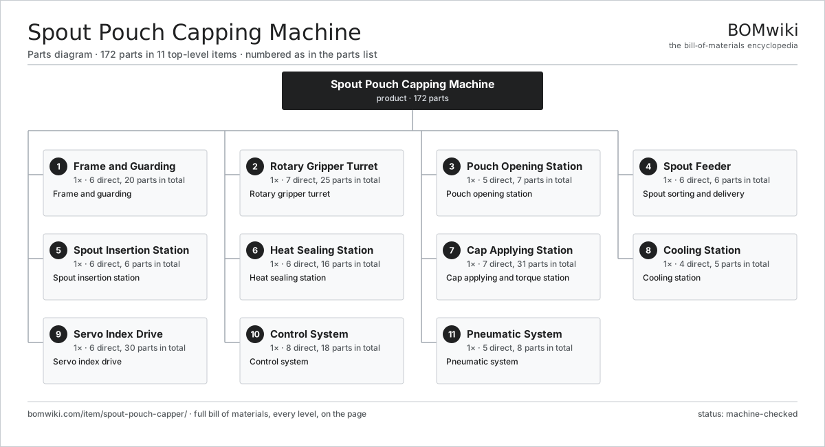
| # | Part | Qty | What it does |
|---|---|---|---|
| 1 | Frame and Guarding 6 parts | 1× | Frame and guarding |
| 2 | Rotary Gripper Turret 7 parts | 1× | Rotary gripper turret |
| 3 | Pouch Opening Station 5 parts | 1× | Pouch opening station |
| 4 | Spout Feeder 6 parts | 1× | Spout sorting and delivery |
| 5 | Spout Insertion Station 6 parts | 1× | Spout insertion station |
| 6 | Heat Sealing Station 6 parts | 1× | Heat sealing station |
| 7 | Cap Applying Station 7 parts | 1× | Cap applying and torque station |
| 8 | Cooling Station 4 parts | 1× | Cooling station |
| 9 | Servo Index Drive 6 parts | 1× | Servo index drive |
| 10 | Control System 8 parts | 1× | Control system |
| 11 | Pneumatic System 5 parts | 1× | Pneumatic system |
3D model
No 3D model yet. Have a CAD file of this? Add a 3D model. STL renders right on this page; STEP, FreeCAD, and OpenSCAD sources are welcome too (openly licensed, like all 3D models on BOMwiki).
Build & assembly graph
expand / collapse · shared sub-assemblies converge · links to related products · est. labourTap an assembly to expand/collapse · tap a part to open it · use “Open page” for any node · drag to pan, scroll to zoom.
Bill of materials for Spout Pouch Capping Machine
11 top-level lines · 85 rows shown · 172 parts total · indented to 3 levels| # | Item / sub-assembly | Part no. | Qty/assy | Ext. qty | Parts | Type |
|---|---|---|---|---|---|---|
| 1 | Frame and Guarding 6 parts | spout-pouch-capper-frame | 1× | 1 | 20 | assembly |
| 1.1 | Base Weldment | spout-pouch-capper-base-weldment | 1× | 1 | · | part |
| 1.2 | Leveling Foot | spout-pouch-capper-leveling-foot | 6× | 6 | · | part |
| 1.3 | Guard Door | spout-pouch-capper-guard-door | 3× | 3 | · | part |
| 1.4 | Guard Panel | spout-pouch-capper-guard-panel | 6× | 6 | · | part |
| 1.5 | Door Interlock | spout-pouch-capper-door-interlock | 3× | 3 | · | part |
| 1.6 | Fastener Set | fastener-set | 1× | 1 | · | part |
| 2 | Rotary Gripper Turret 7 parts | spout-pouch-capper-turret | 1× | 1 | 25 | assembly |
| 2.1 | Turret Plate | spout-pouch-capper-turret-plate | 1× | 1 | · | part |
| 2.2 | Pouch Gripper | spout-pouch-capper-pouch-gripper | 16× | 16 | · | part |
| 2.3 | Gripper Cam | spout-pouch-capper-gripper-cam | 1× | 1 | · | part |
| 2.4 | Infeed Conveyor | spout-pouch-capper-infeed-conveyor | 1× | 1 | · | part |
| 2.5 | Pouch Magazine | spout-pouch-capper-pouch-magazine | 1× | 1 | · | part |
| 2.6 | Discharge Chute | spout-pouch-capper-discharge-chute | 1× | 1 | · | part |
| 2.7 | Ball Bearing | ball-bearing | 4× | 4 | · | part |
| 3 | Pouch Opening Station 5 parts | spout-pouch-capper-opening-station | 1× | 1 | 7 | assembly |
| 3.1 | Vacuum Cup | spout-pouch-capper-vacuum-cup | 2× | 2 | · | part |
| 3.2 | Vacuum Generator | spout-pouch-capper-vacuum-pump | 1× | 1 | · | part |
| 3.3 | Opening Finger | spout-pouch-capper-opening-finger | 2× | 2 | · | part |
| 3.4 | Finger Cylinder | spout-pouch-capper-finger-cylinder | 1× | 1 | · | part |
| 3.5 | Open Sensor | spout-pouch-capper-open-sensor | 1× | 1 | · | part |
| 4 | Spout Feeder 6 parts | spout-pouch-capper-spout-feeder | 1× | 1 | 6 | assembly |
| 4.1 | Vibratory Bowl | spout-pouch-capper-vibratory-bowl | 1× | 1 | · | part |
| 4.2 | Bowl Drive | spout-pouch-capper-bowl-drive | 1× | 1 | · | part |
| 4.3 | Spout Chute | spout-pouch-capper-spout-chute | 1× | 1 | · | part |
| 4.4 | Escapement | spout-pouch-capper-escapement | 1× | 1 | · | part |
| 4.5 | Spout Sensor | spout-pouch-capper-spout-sensor | 1× | 1 | · | part |
| 4.6 | Spout Hopper | spout-pouch-capper-hopper | 1× | 1 | · | part |
| 5 | Spout Insertion Station 6 parts | spout-pouch-capper-insert-station | 1× | 1 | 6 | assembly |
| 5.1 | Insert Head | spout-pouch-capper-insert-head | 1× | 1 | · | part |
| 5.2 | Insert Gripper | spout-pouch-capper-insert-gripper | 1× | 1 | · | part |
| 5.3 | Insert Slide | spout-pouch-capper-insert-slide | 1× | 1 | · | part |
| 5.4 | Insert Cylinder | spout-pouch-capper-insert-cylinder | 1× | 1 | · | part |
| 5.5 | Depth Stop | spout-pouch-capper-depth-stop | 1× | 1 | · | part |
| 5.6 | Linear Guide Rail | linear-guide | 1× | 1 | · | part |
| 6 | Heat Sealing Station 6 parts | spout-pouch-capper-seal-station | 1× | 1 | 16 | assembly |
| 6.1 | Preheat Jaw | spout-pouch-capper-preheat-jaw | 2× | 2 | · | part |
| 6.2 | Seal Jaw | spout-pouch-capper-seal-jaw | 2× | 2 | · | part |
| 6.3 | Heating Element | heating-element | 4× | 4 | · | part |
| 6.4 | Jaw Cylinder | spout-pouch-capper-jaw-cylinder | 2× | 2 | · | part |
| 6.5 | Thermocouple | spout-pouch-capper-thermocouple | 4× | 4 | · | part |
| 6.6 | Seal Profile Insert | spout-pouch-capper-seal-profile | 2× | 2 | · | part |
| 7 | Cap Applying Station 7 parts | spout-pouch-capper-cap-station | 1× | 1 | 31 | assembly |
| 7.1 | Cap Bowl | spout-pouch-capper-cap-bowl | 1× | 1 | · | part |
| 7.2 | Cap Chute | spout-pouch-capper-cap-chute | 1× | 1 | · | part |
| 7.3 | Cap Chuck | spout-pouch-capper-chuck | 1× | 1 | · | part |
| 7.4 | Torque Clutch | spout-pouch-capper-torque-clutch | 1× | 1 | · | part |
| 7.5 | Cap Spindle | spout-pouch-capper-cap-spindle | 1× | 1 | · | part |
| 7.6 | Servo Motor 4 parts | servo-motor | 1× | 1 | 24 | assembly |
| 7.6.1 | Stator Assembly 3 parts + deeper › | stator-assembly | 1× | 1 | 3 | assembly |
| 7.6.2 | Rotor Assembly 4 parts + deeper › | rotor-assembly | 1× | 1 | 19 | assembly |
| 7.6.3 | Encoder | encoder | 1× | 1 | · | part |
| 7.6.4 | Motor Housing | motor-housing | 1× | 1 | · | part |
| 7.7 | Ball Bearing | ball-bearing | 2× | 2 | · | part |
| 8 | Cooling Station 4 parts | spout-pouch-capper-cooling-station | 1× | 1 | 5 | assembly |
| 8.1 | Cooling Jaw | spout-pouch-capper-cooling-jaw | 2× | 2 | · | part |
| 8.2 | Cooling Cylinder | spout-pouch-capper-cooling-cylinder | 1× | 1 | · | part |
| 8.3 | Water Block | spout-pouch-capper-water-block | 1× | 1 | · | part |
| 8.4 | O-Ring Set | oring-set | 1× | 1 | · | part |
| 9 | Servo Index Drive 6 parts | spout-pouch-capper-drive | 1× | 1 | 30 | assembly |
| 9.1 | Servo Motor 4 parts | servo-motor | 1× | 1 | 24 | assembly |
| 9.1.1 | Stator Assembly 3 parts + deeper › | stator-assembly | 1× | 1 | 3 | assembly |
| 9.1.2 | Rotor Assembly 4 parts + deeper › | rotor-assembly | 1× | 1 | 19 | assembly |
| 9.1.3 | Encoder | encoder | 1× | 1 | · | part |
| 9.1.4 | Motor Housing | motor-housing | 1× | 1 | · | part |
| 9.2 | Servo Drive | spout-pouch-capper-servo-drive | 1× | 1 | · | part |
| 9.3 | Cam Indexer | spout-pouch-capper-cam-indexer | 1× | 1 | · | part |
| 9.4 | Gearbox Housing | gearbox-housing | 1× | 1 | · | part |
| 9.5 | Helical Gear Pair | gear-pair | 1× | 1 | · | part |
| 9.6 | Ball Bearing | ball-bearing | 2× | 2 | · | part |
| 10 | Control System 8 parts | spout-pouch-capper-control | 1× | 1 | 18 | assembly |
| 10.1 | PLC | spout-pouch-capper-plc | 1× | 1 | · | part |
| 10.2 | HMI Touchscreen | spout-pouch-capper-hmi | 1× | 1 | · | part |
| 10.3 | Temperature Controller | spout-pouch-capper-temp-controller | 1× | 1 | · | part |
| 10.4 | Reject Arm | spout-pouch-capper-reject-arm | 1× | 1 | · | part |
| 10.5 | Power Supply | power-supply | 1× | 1 | · | part |
| 10.6 | Relay | relay | 4× | 4 | · | part |
| 10.7 | Wire Bundle | wire-bundle | 1× | 1 | · | part |
| 10.8 | Connector | connector | 8× | 8 | · | part |
| 11 | Pneumatic System 5 parts | spout-pouch-capper-pneumatics | 1× | 1 | 8 | assembly |
| 11.1 | Filter-Regulator | spout-pouch-capper-fr-unit | 1× | 1 | · | part |
| 11.2 | Valve Bank | spout-pouch-capper-valve-bank | 1× | 1 | · | part |
| 11.3 | Air Cylinder | spout-pouch-capper-air-cylinder | 4× | 4 | · | part |
| 11.4 | Air Tubing | spout-pouch-capper-air-tubing | 1× | 1 | · | part |
| 11.5 | Pressure Sensor | pressure-sensor | 1× | 1 | · | part |
Related products
same domain, ranked by shared parts Industrial Screen Printing Press
162 parts · shares 8 with this page
Wraparound Case Packer
278 parts · shares 8 with this page
Counter-Pressure Filler
519 parts · shares 7 with this page
Industrial Screen Printing Press
162 parts · shares 8 with this page
Wraparound Case Packer
278 parts · shares 8 with this page
Counter-Pressure Filler
519 parts · shares 7 with this page
 Digital Inkjet Web Press
3,001 parts · shares 7 with this page
Gravity Filling Machine
177 parts · shares 6 with this page
Digital Inkjet Web Press
3,001 parts · shares 7 with this page
Gravity Filling Machine
177 parts · shares 6 with this page
Sourcing: possible vendors
Browse the supplier directory → Prices, MOQ, and lead times are algorithmic estimates, not quotes, and not claims about these companies. Company mappings are curated by keyword; est. price band $10k–$3M. How estimates work| Vendor | HQ | Specialty | MOQ | Lead time |
|---|---|---|---|---|
| heidelberg.com ↗ | Heidelberg, DE | Printing presses | 10 units | 12–22 wks |
|
🇨🇭Bobst
bobst.com ↗
|
Lausanne, CH | Packaging machinery | 10 units | 12–22 wks |
| koenig-bauer.com ↗ | Würzburg, DE | Printing presses | 10 units | 12–22 wks |
| wuh-group.com ↗ | Lengerich, DE | Flexible packaging machines | 10 units | 12–22 wks |
| markandy.com ↗ | Chesterfield, US | Label presses | 10 units | 12–22 wks |
1,416-word article