Liquid Filling Machine
ProductOverview
A liquid filling machine takes empty containers and puts a measured amount of liquid product into each one. The hard part is not moving the liquid but measuring it: every bottle has to receive the same volume within a fraction of a percent so the line meets its label claim without giving away product. Containers arrive on a conveyor, stop at the fill station, a bank of nozzles dives in and dispenses the dose, the nozzles lift clear, and the filled containers move on to capping. Around that simple cycle sits the work of metering accurately, filling without foam, and keeping every product-contact surface clean enough for food, beverage, or pharma duty.
The machine is built on a Frame and Guarding that carries a Bottle Conveyor and Indexing for the containers and a Product Supply System that holds and pressurizes the liquid. The Fill Heads and Nozzles dispense product, the Dosing and Metering System system sets the dose, the Nozzle Lift and Dive Mechanism dives the nozzles in and out, the Clean-in-Place System system cleans the wetted path, the Control System runs the cycle, and the Pneumatic System move the air-driven parts.
Moving and registering containers
Containers ride the Slat Chain, a stainless tabletop chain driven by the Conveyor Gearmotor. The machine fills a batch at a time, so an Entry Gate releases a set of containers into the station, and an Exit Gate holds them until the fill is done. At each position an Index Stop registers the container under its nozzle, and Guide Rail pairs keep the bodies centered to the nozzle pitch. The most important sensor on the conveyor is the Bottle-Present Sensor: it tells the controller which positions actually hold a container, so an empty position never fires its nozzle and sprays product onto the conveyor. That no-bottle-no-fill check is standard on every modern filler. Idler shafts ride on Ball Bearing units and the chain is driven through a Drive Belt.
Product supply
Product reaches the nozzles through the Product Supply System system. A Supply Tank, usually a jacketed 316L buffer, holds product close to the heads so the line never starves between bulk refills. A Level Probe watches the level and a Float Valve admits more product from the bulk tank to keep it topped up. A Sanitary Pump, driven by its Pump Motor, lifts product to a Supply Manifold that splits flow evenly to every head. The path is plumbed in sanitary parts: Product Hose runs from the manifold to each nozzle, Tri-Clamp Fitting fittings join the piping for tool-free teardown, and an O-Ring Set of food-grade gaskets seals the joints.
Fill heads and how the fill works
The Fill Heads and Nozzles are where product enters the container. Each Nozzle Body carries a Shutoff Valve, a Diving Tube, and a Nozzle Tip. The diving tube reaches near the bottom of the container and fills from the bottom up as the liquid level rises, which keeps the product below the stream and limits foaming on anything that aerates easily. At the end of the fill the spring-loaded shutoff valve snaps closed so the nozzle does not drip onto the next container or the conveyor. On an overflow filler the nozzle also carries an Overflow Port that draws product back once it reaches a set height, which fills every clear bottle to the same visible level regardless of small volume differences.
Metering the dose
How much each nozzle delivers is set by the Dosing and Metering System system, and this is what separates one filler type from another. A flow-meter filler puts a Flow Meter on each nozzle; the Flow Board totals the volume that has passed and commands the Fill Valve closed at the target, which gives high accuracy across a wide viscosity range. A timed-flow filler instead holds the same Fill Valve open for a fixed time at a known pressure, which is cheaper and works well for thin, free-flowing liquids. Either way a pair of Pressure Sensor units watch product line pressure so the dose stays stable as the supply tank level changes. A Check-Weigh Cell check-weighs a sample fill on startup and after a product change so the controller can trim each nozzle to the exact target volume.
Nozzle motion, cleaning, and control
The whole nozzle bank dives together on the Nozzle Lift and Dive Mechanism. A Servo Motor drives a Ball Screw and Lift Carriage running on Linear Guide Rail rails so the nozzles enter and leave the containers smoothly, while simpler machines use a Dive Cylinder for a fixed stroke. A Lift Sensor confirms the bank is fully up before the conveyor moves. Because the machine handles food and beverage product, the Clean-in-Place System system cleans every wetted path without disassembly: CIP Cup cups dock over each nozzle so cleaning solution recirculates through the CIP Manifold rather than spilling, a Spray Ball washes the supply tank, and CIP Valve valves switch the path between production and cleaning. The Control System system runs the cycle from a PLC with recipes set on the HMI Touchscreen touchscreen, a Reject Arm pushes off any container that came in out of tolerance, and a Power Supply feeds the logic through a Wire Bundle and Connector set. The air-driven gates, dive, and reject run off the Pneumatic System through a Filter-Regulator and Valve Bank.
Variants and use
Fillers are grouped by how they meter and dispense. Gravity fillers let thin liquid fall by head pressure into the bottle and are the cheapest. Pressure fillers seal the nozzle against the bottle and push product in, which suits slightly thicker or carbonated product. Overflow fillers prize an even visible fill line in clear bottles. Flow-meter fillers give the tightest volume accuracy across viscosities, and timed-flow fillers trade some accuracy for low cost on thin product. Thick or chunky product is better handled by a Piston Filling Machine, and dry powders or granules by an Auger Powder Filling Machine, so a plant chooses the filler to match the product rather than fitting product to one machine. Once filled, containers move downstream to a Bottle Capping Machine for closing. A liquid filling line runs anywhere a measured volume goes into a container: water and juice, sauces and oils, detergents and shampoos, and pharmaceutical liquids.
Liquid Filling Machine parts and their functions
9 top-level parts · 188 parts in total · full bill of materials below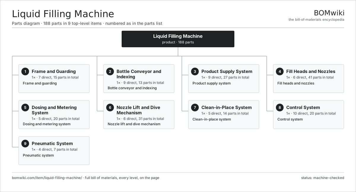
| # | Part | Qty | What it does |
|---|---|---|---|
| 1 | Frame and Guarding 7 parts | 1× | Frame and guarding |
| 2 | Bottle Conveyor and Indexing 9 parts | 1× | Bottle conveyor and indexing |
| 3 | Product Supply System 9 parts | 1× | Product supply system |
| 4 | Fill Heads and Nozzles 6 parts | 1× | Fill heads and nozzles |
| 5 | Dosing and Metering System 5 parts | 1× | Dosing and metering system |
| 6 | Nozzle Lift and Dive Mechanism 6 parts | 1× | Nozzle lift and dive mechanism |
| 7 | Clean-in-Place System 5 parts | 1× | Clean-in-place system |
| 8 | Control System 10 parts | 1× | Control system |
| 9 | Pneumatic System 4 parts | 1× | Pneumatic system |
3D model
No 3D model yet. Have a CAD file of this? Add a 3D model. STL renders right on this page; STEP, FreeCAD, and OpenSCAD sources are welcome too (openly licensed, like all 3D models on BOMwiki).
Build & assembly graph
expand / collapse · shared sub-assemblies converge · links to related products · est. labourTap an assembly to expand/collapse · tap a part to open it · use “Open page” for any node · drag to pan, scroll to zoom.
Bill of materials for Liquid Filling Machine
9 top-level lines · 74 rows shown · 188 parts total · indented to 3 levels| # | Item / sub-assembly | Part no. | Qty/assy | Ext. qty | Parts | Type |
|---|---|---|---|---|---|---|
| 1 | Frame and Guarding 7 parts | liquid-filling-machine-frame | 1× | 1 | 15 | assembly |
| 1.1 | Base Weldment | liquid-filling-machine-base-weldment | 1× | 1 | · | part |
| 1.2 | Leveling Foot | liquid-filling-machine-leveling-foot | 4× | 4 | · | part |
| 1.3 | Guard Door | liquid-filling-machine-guard-door | 2× | 2 | · | part |
| 1.4 | Guard Panel | liquid-filling-machine-guard-panel | 4× | 4 | · | part |
| 1.5 | Door Interlock | liquid-filling-machine-door-interlock | 2× | 2 | · | part |
| 1.6 | Drip Tray | liquid-filling-machine-drip-tray | 1× | 1 | · | part |
| 1.7 | Fastener Set | fastener-set | 1× | 1 | · | part |
| 2 | Bottle Conveyor and Indexing 9 parts | liquid-filling-machine-conveyor | 1× | 1 | 13 | assembly |
| 2.1 | Slat Chain | liquid-filling-machine-slat-chain | 1× | 1 | · | part |
| 2.2 | Conveyor Gearmotor | liquid-filling-machine-conveyor-motor | 1× | 1 | · | part |
| 2.3 | Entry Gate | liquid-filling-machine-entry-gate | 1× | 1 | · | part |
| 2.4 | Exit Gate | liquid-filling-machine-exit-gate | 1× | 1 | · | part |
| 2.5 | Index Stop | liquid-filling-machine-index-stop | 1× | 1 | · | part |
| 2.6 | Guide Rail | liquid-filling-machine-guide-rail | 2× | 2 | · | part |
| 2.7 | Bottle-Present Sensor | liquid-filling-machine-bottle-sensor | 1× | 1 | · | part |
| 2.8 | Drive Belt | drive-belt | 1× | 1 | · | part |
| 2.9 | Ball Bearing | ball-bearing | 4× | 4 | · | part |
| 3 | Product Supply System 9 parts | liquid-filling-machine-product-supply | 1× | 1 | 27 | assembly |
| 3.1 | Supply Tank | liquid-filling-machine-supply-tank | 1× | 1 | · | part |
| 3.2 | Level Probe | liquid-filling-machine-level-probe | 1× | 1 | · | part |
| 3.3 | Float Valve | liquid-filling-machine-float-valve | 1× | 1 | · | part |
| 3.4 | Sanitary Pump | liquid-filling-machine-sanitary-pump | 1× | 1 | · | part |
| 3.5 | Pump Motor | liquid-filling-machine-pump-motor | 1× | 1 | · | part |
| 3.6 | Supply Manifold | liquid-filling-machine-supply-manifold | 1× | 1 | · | part |
| 3.7 | Product Hose | liquid-filling-machine-product-hose | 8× | 8 | · | part |
| 3.8 | Tri-Clamp Fitting | liquid-filling-machine-tri-clamp | 12× | 12 | · | part |
| 3.9 | O-Ring Set | oring-set | 1× | 1 | · | part |
| 4 | Fill Heads and Nozzles 6 parts | liquid-filling-machine-fill-heads | 1× | 1 | 41 | assembly |
| 4.1 | Nozzle Body | liquid-filling-machine-nozzle-body | 8× | 8 | · | part |
| 4.2 | Shutoff Valve | liquid-filling-machine-shutoff-valve | 8× | 8 | · | part |
| 4.3 | Diving Tube | liquid-filling-machine-diving-tube | 8× | 8 | · | part |
| 4.4 | Nozzle Tip | liquid-filling-machine-nozzle-tip | 8× | 8 | · | part |
| 4.5 | Overflow Port | liquid-filling-machine-overflow-port | 8× | 8 | · | part |
| 4.6 | O-Ring Set | oring-set | 1× | 1 | · | part |
| 5 | Dosing and Metering System 5 parts | liquid-filling-machine-metering | 1× | 1 | 20 | assembly |
| 5.1 | Flow Meter | liquid-filling-machine-flow-meter | 8× | 8 | · | part |
| 5.2 | Fill Valve | liquid-filling-machine-fill-valve | 8× | 8 | · | part |
| 5.3 | Pressure Sensor | pressure-sensor | 2× | 2 | · | part |
| 5.4 | Flow Board | liquid-filling-machine-flow-board | 1× | 1 | · | part |
| 5.5 | Check-Weigh Cell | liquid-filling-machine-calibration-cell | 1× | 1 | · | part |
| 6 | Nozzle Lift and Dive Mechanism 6 parts | liquid-filling-machine-nozzle-lift | 1× | 1 | 31 | assembly |
| 6.1 | Servo Motor 4 parts | servo-motor | 1× | 1 | 24 | assembly |
| 6.1.1 | Stator Assembly 3 parts + deeper › | stator-assembly | 1× | 1 | 3 | assembly |
| 6.1.2 | Rotor Assembly 4 parts + deeper › | rotor-assembly | 1× | 1 | 19 | assembly |
| 6.1.3 | Encoder | encoder | 1× | 1 | · | part |
| 6.1.4 | Motor Housing | motor-housing | 1× | 1 | · | part |
| 6.2 | Lift Carriage | liquid-filling-machine-lift-carriage | 1× | 1 | · | part |
| 6.3 | Ball Screw | ball-screw | 1× | 1 | · | part |
| 6.4 | Linear Guide Rail | linear-guide | 2× | 2 | · | part |
| 6.5 | Dive Cylinder | liquid-filling-machine-dive-cylinder | 1× | 1 | · | part |
| 6.6 | Lift Sensor | liquid-filling-machine-lift-sensor | 2× | 2 | · | part |
| 7 | Clean-in-Place System 5 parts | liquid-filling-machine-cip | 1× | 1 | 14 | assembly |
| 7.1 | CIP Cup | liquid-filling-machine-cip-cup | 8× | 8 | · | part |
| 7.2 | CIP Manifold | liquid-filling-machine-cip-manifold | 1× | 1 | · | part |
| 7.3 | CIP Valve | liquid-filling-machine-cip-valve | 2× | 2 | · | part |
| 7.4 | Spray Ball | liquid-filling-machine-spray-ball | 1× | 1 | · | part |
| 7.5 | CIP Connection | liquid-filling-machine-cip-connection | 2× | 2 | · | part |
| 8 | Control System 10 parts | liquid-filling-machine-control | 1× | 1 | 20 | assembly |
| 8.1 | PLC | liquid-filling-machine-plc | 1× | 1 | · | part |
| 8.2 | HMI Touchscreen | liquid-filling-machine-hmi | 1× | 1 | · | part |
| 8.3 | Reject Arm | liquid-filling-machine-reject-arm | 1× | 1 | · | part |
| 8.4 | Power Supply | power-supply | 1× | 1 | · | part |
| 8.5 | Bare PCB | pcb-bare | 1× | 1 | · | part |
| 8.6 | Microcontroller | mcu | 1× | 1 | · | part |
| 8.7 | SMD Passive (R/C/L) | smd-passives | 1× | 1 | · | part |
| 8.8 | Relay | relay | 4× | 4 | · | part |
| 8.9 | Wire Bundle | wire-bundle | 1× | 1 | · | part |
| 8.10 | Connector | connector | 8× | 8 | · | part |
| 9 | Pneumatic System 4 parts | liquid-filling-machine-pneumatics | 1× | 1 | 7 | assembly |
| 9.1 | Filter-Regulator | liquid-filling-machine-fr-unit | 1× | 1 | · | part |
| 9.2 | Valve Bank | liquid-filling-machine-valve-bank | 1× | 1 | · | part |
| 9.3 | Air Cylinder | liquid-filling-machine-air-cylinder | 4× | 4 | · | part |
| 9.4 | Air Tubing | liquid-filling-machine-air-tubing | 1× | 1 | · | part |
Related products
same domain, ranked by shared parts Digital Inkjet Web Press
3,001 parts · shares 7 with this page
Gravity Filling Machine
177 parts · shares 7 with this page
Digital Inkjet Web Press
3,001 parts · shares 7 with this page
Gravity Filling Machine
177 parts · shares 7 with this page
 Industrial Screen Printing Press
162 parts · shares 7 with this page
Industrial Screen Printing Press
162 parts · shares 7 with this page
 Piston Filling Machine
112 parts · shares 7 with this page
Ream Wrapping Machine
540 parts · shares 6 with this page
Piston Filling Machine
112 parts · shares 7 with this page
Ream Wrapping Machine
540 parts · shares 6 with this page
 Paper Tube Winding Machine
122 parts · shares 5 with this page
Paper Tube Winding Machine
122 parts · shares 5 with this page
Sourcing: possible vendors
Browse the supplier directory → Prices, MOQ, and lead times are algorithmic estimates, not quotes, and not claims about these companies. Company mappings are curated by keyword; est. price band $10k–$3M. How estimates work| Vendor | HQ | Specialty | MOQ | Lead time |
|---|---|---|---|---|
| heidelberg.com ↗ | Heidelberg, DE | Printing presses | 10 units | 12–22 wks |
|
🇨🇭Bobst
bobst.com ↗
|
Lausanne, CH | Packaging machinery | 10 units | 12–22 wks |
| koenig-bauer.com ↗ | Würzburg, DE | Printing presses | 10 units | 12–22 wks |
| wuh-group.com ↗ | Lengerich, DE | Flexible packaging machines | 10 units | 12–22 wks |
| markandy.com ↗ | Chesterfield, US | Label presses | 10 units | 12–22 wks |
1,190-word article