Corrugated Case Maker
ProductOverview
A corrugated case maker, known in the trade as a flexo folder gluer, turns flat corrugated board sheets into finished shipping boxes in one pass. It prints the customer artwork, cuts the corner slots and any handle holes, creases the fold lines, folds the blank into a flat tube, glues the seam, and stacks the finished boxes for strapping. The most common box it makes is the regular slotted carton, the plain brown box with four flaps top and bottom, but the same machine handles die-cut shapes and printed retail cases.
Board enters at the Sheet Feeder, passes through one or more Flexo Print Unit sections, is cut at the Slotter and Die Section and creased at the Creaser Section, then folded and bonded in the Folder Gluer. The Counter Ejector counts and bundles the output. All sections turn in phase under the Main Drive and Registration and registration system, and the Control System system stores each job so a repeat order sets up in minutes.
Feeding
The Sheet Feeder separates one sheet at a time from the stack and sends it into the press squarely and in time with the cylinders. A Lift Table raises the stack so the top sheet is always at the same height. The Lead-Edge Feeder feeder, a vacuum head, grabs the front edge of the top sheet and pulls it into the nip, which gives better register than the older bottom-feed method because the sheet is timed from its lead edge. A Front Gate sets the gap so only one sheet passes, and Side Guide rails keep the stack edge straight. Good feeding is the foundation of print register, since every later station times itself from when the sheet arrives.
Flexo printing
Each Flexo Print Unit lays down one colour by flexography, a relief printing process using a soft rubber or photopolymer plate. The Anilox Roll roll is the heart of it: its surface is engraved with millions of tiny cells that hold a fixed volume of ink, so it meters a controlled film onto the plate regardless of press speed. A Doctor Blade Chamber floods the anilox and a doctor blade wipes the surface clean, leaving ink only in the cells. The Plate Cylinder carries the plate, which transfers the image to the board as it passes over the Impression Roll. Water-based ink is fed by an Ink Pump and dries by absorption into the liner. Adding a second print unit gives a second colour, each phased to the first by the registration system.
Slotting, dies, and creasing
After printing, the blank must be shaped so it will fold into a box. The Slotter and Die Section carries four Slotting Head units, each with a Slot Knife that cuts one corner slot. These slots are what let the four flaps fold independently. The heads slide on their shaft to match the box size, set automatically by the Slotter and Die Section servo from the stored job. A Trim Knife cuts the glue tab and trims the blank to length. For shaped boxes or hand holes, a Rotary Die Cylinder carries a steel-rule die that cuts against a urethane Anvil Roll. The Creaser Section then presses fold lines into the board: a Creasing Wheel pushes the board into a matching Crease Rail to crush a clean hinge so the walls fold without cracking the liner.
Folding and gluing
The Folder Gluer turns the flat slotted blank into a flat-folded tube. As the blank rides on Folding Belt belts, curved Folding Bar guides lift the two side panels and fold them in along the body creases until the manufacturer joint tab overlaps the far panel. Just before they meet, a Glue Gun lays a glue bead on the tab. The Squaring Belt section then holds the box square while the glue grabs, which sets whether the finished box is square or skewed. Folding accuracy here decides the fishtail and gap tolerances that the box buyer measures on the seam.
Counting and ejection
Finished boxes leave flat and stacked in a shingle. The Counter Ejector uses a Count Sensor photocell to count each box into a Layboy Hopper until the bundle reaches the set count. A Bundle Jogger squares the bundle edges and the Ejector Arm pushes it out to the strapper or palletizer. Splitting the run into even counted bundles is what lets the box plant ship and invoice by exact quantity.
Drive, control, and use
The Main Drive and Registration runs the sections as a synchronized set with servo motors and registration encoders, and uses Registration Encoder feedback to phase the print plates to the slots. The Control System system, built around the Machine PLC, stores box dimensions, head positions, and print phase as a recallable job, so changeover between orders is fast. A case maker sits at the heart of a box plant, taking sheets from the corrugator and turning out the brown boxes used across shipping, food, and industrial packaging. Speed, register accuracy, and quick changeover are the measures that matter, because box orders are short and varied.
Corrugated Case Maker parts and their functions
8 top-level parts · 240 parts in total · full bill of materials below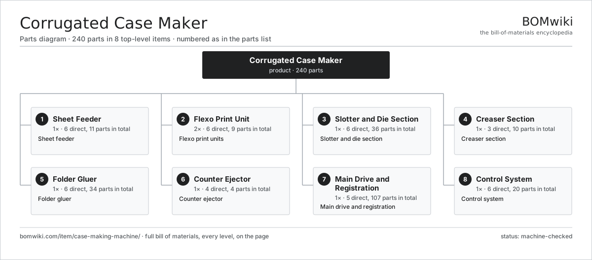
| # | Part | Qty | What it does |
|---|---|---|---|
| 1 | Sheet Feeder 6 parts | 1× | Sheet feeder |
| 2 | Flexo Print Unit 6 parts | 2× | Flexo print units |
| 3 | Slotter and Die Section 6 parts | 1× | Slotter and die section |
| 4 | Creaser Section 3 parts | 1× | Creaser section |
| 5 | Folder Gluer 6 parts | 1× | Folder gluer |
| 6 | Counter Ejector 4 parts | 1× | Counter ejector |
| 7 | Main Drive and Registration 5 parts | 1× | Main drive and registration |
| 8 | Control System 6 parts | 1× | Control system |
3D model
No 3D model yet. Have a CAD file of this? Add a 3D model. STL renders right on this page; STEP, FreeCAD, and OpenSCAD sources are welcome too (openly licensed, like all 3D models on BOMwiki).
Build & assembly graph
expand / collapse · shared sub-assemblies converge · links to related products · est. labourTap an assembly to expand/collapse · tap a part to open it · use “Open page” for any node · drag to pan, scroll to zoom.
Bill of materials for Corrugated Case Maker
8 top-level lines · 65 rows shown · 240 parts total · indented to 3 levels| # | Item / sub-assembly | Part no. | Qty/assy | Ext. qty | Parts | Type |
|---|---|---|---|---|---|---|
| 1 | Sheet Feeder 6 parts | case-making-machine-feeder | 1× | 1 | 11 | assembly |
| 1.1 | Lift Table | case-making-machine-feed-table | 1× | 1 | · | part |
| 1.2 | Front Gate | case-making-machine-front-gate | 1× | 1 | · | part |
| 1.3 | Feed Roll | case-making-machine-feed-roll | 2× | 2 | · | part |
| 1.4 | Lead-Edge Feeder | case-making-machine-lead-edge | 1× | 1 | · | part |
| 1.5 | Side Guide | case-making-machine-side-guide | 2× | 2 | · | part |
| 1.6 | Ball Bearing | ball-bearing | 4× | 4 | · | part |
| 2 | Flexo Print Unit 6 parts | case-making-machine-print-unit | 2× | 2 | 9 | assembly |
| 2.1 | Plate Cylinder | case-making-machine-plate-cylinder | 1× | 2 | · | part |
| 2.2 | Anilox Roll | case-making-machine-anilox | 1× | 2 | · | part |
| 2.3 | Doctor Blade Chamber | case-making-machine-ink-chamber | 1× | 2 | · | part |
| 2.4 | Impression Roll | case-making-machine-impression-roll | 1× | 2 | · | part |
| 2.5 | Ink Pump | case-making-machine-ink-pump | 1× | 2 | · | part |
| 2.6 | Ball Bearing | ball-bearing | 4× | 8 | · | part |
| 3 | Slotter and Die Section 6 parts | case-making-machine-slotter | 1× | 1 | 36 | assembly |
| 3.1 | Slotting Head | case-making-machine-slot-head | 4× | 4 | · | part |
| 3.2 | Slot Knife | case-making-machine-slot-knife | 4× | 4 | · | part |
| 3.3 | Trim Knife | case-making-machine-trim-knife | 2× | 2 | · | part |
| 3.4 | Rotary Die Cylinder | case-making-machine-die-cylinder | 1× | 1 | · | part |
| 3.5 | Anvil Roll | case-making-machine-anvil-roll | 1× | 1 | · | part |
| 3.6 | Servo Motor 4 parts | servo-motor | 1× | 1 | 24 | assembly |
| 3.6.1 | Stator Assembly 3 parts + deeper › | stator-assembly | 1× | 1 | 3 | assembly |
| 3.6.2 | Rotor Assembly 4 parts + deeper › | rotor-assembly | 1× | 1 | 19 | assembly |
| 3.6.3 | Encoder | encoder | 1× | 1 | · | part |
| 3.6.4 | Motor Housing | motor-housing | 1× | 1 | · | part |
| 4 | Creaser Section 3 parts | case-making-machine-creaser | 1× | 1 | 10 | assembly |
| 4.1 | Creasing Wheel | case-making-machine-crease-wheel | 4× | 4 | · | part |
| 4.2 | Crease Rail | case-making-machine-crease-rail | 4× | 4 | · | part |
| 4.3 | Score Shaft | case-making-machine-score-shaft | 2× | 2 | · | part |
| 5 | Folder Gluer 6 parts | case-making-machine-folder-gluer | 1× | 1 | 34 | assembly |
| 5.1 | Folding Belt | case-making-machine-fold-belt | 2× | 2 | · | part |
| 5.2 | Folding Bar | case-making-machine-fold-bar | 2× | 2 | · | part |
| 5.3 | Glue Gun | case-making-machine-glue-gun | 2× | 2 | · | part |
| 5.4 | Squaring Belt | case-making-machine-squaring-belt | 2× | 2 | · | part |
| 5.5 | Drive Belt | drive-belt | 2× | 2 | · | part |
| 5.6 | Servo Motor 4 parts | servo-motor | 1× | 1 | 24 | assembly |
| 5.6.1 | Stator Assembly 3 parts + deeper › | stator-assembly | 1× | 1 | 3 | assembly |
| 5.6.2 | Rotor Assembly 4 parts + deeper › | rotor-assembly | 1× | 1 | 19 | assembly |
| 5.6.3 | Encoder | encoder | 1× | 1 | · | part |
| 5.6.4 | Motor Housing | motor-housing | 1× | 1 | · | part |
| 6 | Counter Ejector 4 parts | case-making-machine-counter-ejector | 1× | 1 | 4 | assembly |
| 6.1 | Count Sensor | case-making-machine-counter-sensor | 1× | 1 | · | part |
| 6.2 | Layboy Hopper | case-making-machine-hopper | 1× | 1 | · | part |
| 6.3 | Ejector Arm | case-making-machine-eject-arm | 1× | 1 | · | part |
| 6.4 | Bundle Jogger | case-making-machine-jogger | 1× | 1 | · | part |
| 7 | Main Drive and Registration 5 parts | case-making-machine-drive | 1× | 1 | 107 | assembly |
| 7.1 | Servo Motor 4 parts | servo-motor | 4× | 4 | 24 | assembly |
| 7.1.1 | Stator Assembly 3 parts + deeper › | stator-assembly | 1× | 4 | 3 | assembly |
| 7.1.2 | Rotor Assembly 4 parts + deeper › | rotor-assembly | 1× | 4 | 19 | assembly |
| 7.1.3 | Encoder | encoder | 1× | 4 | · | part |
| 7.1.4 | Motor Housing | motor-housing | 1× | 4 | · | part |
| 7.2 | Gearbox Housing | gearbox-housing | 1× | 1 | · | part |
| 7.3 | Helical Gear Pair | gear-pair | 4× | 4 | · | part |
| 7.4 | Registration Encoder | case-making-machine-register-encoder | 4× | 4 | · | part |
| 7.5 | Ball Screw | ball-screw | 2× | 2 | · | part |
| 8 | Control System 6 parts | case-making-machine-control | 1× | 1 | 20 | assembly |
| 8.1 | Machine PLC 3 parts | case-making-machine-plc | 1× | 1 | 3 | assembly |
| 8.1.1 | Bare PCB | pcb-bare | 1× | 1 | · | part |
| 8.1.2 | Microcontroller | mcu | 1× | 1 | · | part |
| 8.1.3 | SMD Passive (R/C/L) | smd-passives | 1× | 1 | · | part |
| 8.2 | LCD Panel | lcd-panel | 1× | 1 | · | part |
| 8.3 | Power Supply | power-supply | 1× | 1 | · | part |
| 8.4 | Relay | relay | 6× | 6 | · | part |
| 8.5 | Wire Bundle | wire-bundle | 1× | 1 | · | part |
| 8.6 | Connector | connector | 8× | 8 | · | part |
Related products
same domain, ranked by shared parts Industrial Screen Printing Press
162 parts · shares 6 with this page
Industrial Screen Printing Press
162 parts · shares 6 with this page
 Paper Tube Winding Machine
122 parts · shares 5 with this page
Paper Tube Winding Machine
122 parts · shares 5 with this page
 Digital Inkjet Web Press
3,001 parts · shares 5 with this page
Gravity Filling Machine
177 parts · shares 5 with this page
Digital Inkjet Web Press
3,001 parts · shares 5 with this page
Gravity Filling Machine
177 parts · shares 5 with this page
 Cartoning Machine
280 parts · shares 4 with this page
Cartoning Machine
280 parts · shares 4 with this page
 Liquid Filling Machine
188 parts · shares 4 with this page
Liquid Filling Machine
188 parts · shares 4 with this page
Sourcing: possible vendors
Browse the supplier directory → Prices, MOQ, and lead times are algorithmic estimates, not quotes, and not claims about these companies. Company mappings are curated by keyword; est. price band $10k–$3M. How estimates work| Vendor | HQ | Specialty | MOQ | Lead time |
|---|---|---|---|---|
| heidelberg.com ↗ | Heidelberg, DE | Printing presses | 10 units | 12–22 wks |
|
🇨🇭Bobst
bobst.com ↗
|
Lausanne, CH | Packaging machinery | 10 units | 12–22 wks |
| koenig-bauer.com ↗ | Würzburg, DE | Printing presses | 10 units | 12–22 wks |
| wuh-group.com ↗ | Lengerich, DE | Flexible packaging machines | 10 units | 12–22 wks |
| markandy.com ↗ | Chesterfield, US | Label presses | 10 units | 12–22 wks |
952-word article