Rotary Die Cutter
ProductAlso known as: Rotary Die-Cutting Press
Overview
A rotary die cutter cuts and creases shapes out of moving web or sheet stock by rolling a die against an anvil, instead of stamping with a flat reciprocating die. Because the cut happens continuously in a nip rather than in stop-start strokes, it runs far faster and suits labels, folding cartons, gaskets, and light corrugated blanks. The flexible magnetic die used here is a thin etched steel sheet wrapped onto a cylinder, which is cheap to make and quick to change compared with a solid rotary die.
The cylinders run in the rigid Frame & Side Plates, and the Main Drive turns the whole train together so cutting and anvil surfaces stay in mesh.
How it works
Stock enters through the Infeed & Feed Rollers, whose driven nip rollers meter it into the nip at the cylinder's surface speed so the web is neither stretched nor bunched. At the Cutting Station, the Magnetic Die is held by magnetism to the cutting cylinder and pressed against the hardened Anvil Cylinder; as the stock passes between them the raised rules shear the outline and crease the fold lines in one rotation. Adjusters set the cylinder gap to control cut depth without nicking the anvil.
For pre-printed stock the cut must land on the print, so the Registration servo and encoder read a printed mark and micro-advance or retard the cutting cylinder to hold register. Past the cut, the Waste Stripping station lifts the waste matrix and trim away with pin rollers and a winder, leaving clean blanks that the Delivery belt decelerates and stacks. The Control Panel coordinates line speed, register correction, and stripping from a single graphic interface.
Rotary Die Cutter parts and their functions
10 top-level parts · 148 parts in total · full bill of materials below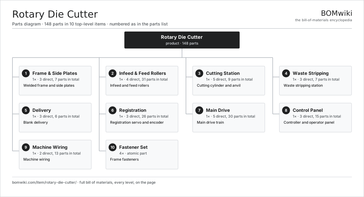
| # | Part | Qty | What it does |
|---|---|---|---|
| 1 | Frame & Side Plates 3 parts | 1× | Welded frame and side plates |
| 2 | Infeed & Feed Rollers 4 parts | 1× | Infeed and feed rollers |
| 3 | Cutting Station 5 parts | 1× | Cutting cylinder and anvil |
| 4 | Waste Stripping 3 parts | 1× | Waste stripping station |
| 5 | Delivery 3 parts | 1× | Blank delivery |
| 6 | Registration 3 parts | 1× | Registration servo and encoder |
| 7 | Main Drive 5 parts | 1× | Main drive train |
| 8 | Control Panel 3 parts | 1× | Controller and operator panel |
| 9 | Machine Wiring 2 parts | 1× | Machine wiring |
| 10 | Fastener Set | 4× | Frame fasteners |
3D model
No 3D model yet. Have a CAD file of this? Add a 3D model. STL renders right on this page; STEP, FreeCAD, and OpenSCAD sources are welcome too (openly licensed, like all 3D models on BOMwiki).
Build & assembly graph
expand / collapse · shared sub-assemblies converge · links to related products · est. labourTap an assembly to expand/collapse · tap a part to open it · use “Open page” for any node · drag to pan, scroll to zoom.
Bill of materials for Rotary Die Cutter
10 top-level lines · 54 rows shown · 148 parts total · indented to 3 levels| # | Item / sub-assembly | Part no. | Qty/assy | Ext. qty | Parts | Type |
|---|---|---|---|---|---|---|
| 1 | Frame & Side Plates 3 parts | rotary-die-cutter-frame | 1× | 1 | 7 | assembly |
| 1.1 | Side Plate | rotary-die-cutter-side-plate | 2× | 2 | · | part |
| 1.2 | Tie Bar | rotary-die-cutter-tie-bar | 4× | 4 | · | part |
| 1.3 | Fastener Set | fastener-set | 1× | 1 | · | part |
| 2 | Infeed & Feed Rollers 4 parts | rotary-die-cutter-infeed | 1× | 1 | 31 | assembly |
| 2.1 | Feed Roller | rotary-die-cutter-feed-roller | 2× | 2 | · | part |
| 2.2 | Infeed Motor 3 parts | rotary-die-cutter-infeed-motor | 1× | 1 | 24 | assembly |
| 2.2.1 | Stator Assembly 3 parts + deeper › | stator-assembly | 1× | 1 | 3 | assembly |
| 2.2.2 | Rotor Assembly 4 parts + deeper › | rotor-assembly | 1× | 1 | 19 | assembly |
| 2.2.3 | Ball Bearing | ball-bearing | 2× | 2 | · | part |
| 2.3 | Helical Gear Pair | gear-pair | 1× | 1 | · | part |
| 2.4 | Ball Bearing | ball-bearing | 4× | 4 | · | part |
| 3 | Cutting Station 5 parts | rotary-die-cutter-cutting-station | 1× | 1 | 9 | assembly |
| 3.1 | Cutting Cylinder | rotary-die-cutter-cylinder | 1× | 1 | · | part |
| 3.2 | Magnetic Die | rotary-die-cutter-magnetic-die | 1× | 1 | · | part |
| 3.3 | Anvil Cylinder | rotary-die-cutter-anvil | 1× | 1 | · | part |
| 3.4 | Ball Bearing | ball-bearing | 4× | 4 | · | part |
| 3.5 | Cut Pressure Adjuster | rotary-die-cutter-pressure-adjuster | 2× | 2 | · | part |
| 4 | Waste Stripping 3 parts | rotary-die-cutter-stripping | 1× | 1 | 7 | assembly |
| 4.1 | Strip Roller | rotary-die-cutter-strip-roller | 2× | 2 | · | part |
| 4.2 | Waste Winder | rotary-die-cutter-waste-winder | 1× | 1 | · | part |
| 4.3 | Ball Bearing | ball-bearing | 4× | 4 | · | part |
| 5 | Delivery 3 parts | rotary-die-cutter-delivery | 1× | 1 | 6 | assembly |
| 5.1 | Delivery Belt | rotary-die-cutter-delivery-belt | 1× | 1 | · | part |
| 5.2 | Drive Belt | drive-belt | 1× | 1 | · | part |
| 5.3 | Ball Bearing | ball-bearing | 4× | 4 | · | part |
| 6 | Registration 3 parts | rotary-die-cutter-registration | 1× | 1 | 26 | assembly |
| 6.1 | Registration Servo 3 parts | rotary-die-cutter-reg-servo | 1× | 1 | 24 | assembly |
| 6.1.1 | Stator Assembly 3 parts + deeper › | stator-assembly | 1× | 1 | 3 | assembly |
| 6.1.2 | Rotor Assembly 4 parts + deeper › | rotor-assembly | 1× | 1 | 19 | assembly |
| 6.1.3 | Ball Bearing | ball-bearing | 2× | 2 | · | part |
| 6.2 | Encoder | encoder | 1× | 1 | · | part |
| 6.3 | Register Mark Sensor | rotary-die-cutter-reg-sensor | 1× | 1 | · | part |
| 7 | Main Drive 5 parts | rotary-die-cutter-drive | 1× | 1 | 30 | assembly |
| 7.1 | Main Drive Motor 3 parts | rotary-die-cutter-main-motor | 1× | 1 | 24 | assembly |
| 7.1.1 | Stator Assembly 3 parts + deeper › | stator-assembly | 1× | 1 | 3 | assembly |
| 7.1.2 | Rotor Assembly 4 parts + deeper › | rotor-assembly | 1× | 1 | 19 | assembly |
| 7.1.3 | Ball Bearing | ball-bearing | 2× | 2 | · | part |
| 7.2 | Gearbox Housing | gearbox-housing | 1× | 1 | · | part |
| 7.3 | Helical Gear Pair | gear-pair | 2× | 2 | · | part |
| 7.4 | Drive Belt | drive-belt | 1× | 1 | · | part |
| 7.5 | Oil Seal | oil-seal | 2× | 2 | · | part |
| 8 | Control Panel 3 parts | rotary-die-cutter-control-panel | 1× | 1 | 15 | assembly |
| 8.1 | Control Board 4 parts | rotary-die-cutter-control-board | 1× | 1 | 13 | assembly |
| 8.1.1 | Bare PCB | pcb-bare | 1× | 1 | · | part |
| 8.1.2 | Microcontroller | mcu | 1× | 1 | · | part |
| 8.1.3 | SMD Passive (R/C/L) | smd-passives | 1× | 1 | · | part |
| 8.1.4 | Connector | connector | 10× | 10 | · | part |
| 8.2 | Compute SoC Module | soc-module | 1× | 1 | · | part |
| 8.3 | LCD Panel | lcd-panel | 1× | 1 | · | part |
| 9 | Machine Wiring 2 parts | rotary-die-cutter-wiring | 1× | 1 | 13 | assembly |
| 9.1 | Wire Bundle | wire-bundle | 1× | 1 | · | part |
| 9.2 | Connector | connector | 12× | 12 | · | part |
| 10 | Fastener Set | fastener-set | 4× | 4 | · | part |
Something wrong in this list? Report a problem with this BOM.
Related products
same domain, ranked by shared parts Cartoning Machine
280 parts · shares 5 with this page
Corrugator (Single-Facer)
875 parts · shares 5 with this page
 Gravure Printing Press
2,094 parts · shares 5 with this page
 Offset Printing Press
1,931 parts · shares 5 with this page
Plastic Bag Making Machine
652 parts · shares 5 with this page
 Robotic Palletizer
393 parts · shares 4 with this page
Sourcing: possible vendors
Browse the supplier directory → Prices, MOQ, and lead times are algorithmic estimates, not quotes, and not claims about these companies. Company mappings are curated by keyword; est. price band $10k–$3M. How estimates work| Vendor | HQ | Specialty | MOQ | Lead time |
|---|---|---|---|---|
| heidelberg.com ↗ | Heidelberg, DE | Printing presses | 10 units | 12–22 wks |
|
🇨🇭Bobst
bobst.com ↗
|
Lausanne, CH | Packaging machinery | 10 units | 12–22 wks |
| koenig-bauer.com ↗ | Würzburg, DE | Printing presses | 10 units | 12–22 wks |
| wuh-group.com ↗ | Lengerich, DE | Flexible packaging machines | 10 units | 12–22 wks |
| markandy.com ↗ | Chesterfield, US | Label presses | 10 units | 12–22 wks |
304-word article