Vacuum Lifting Beam
ProductOverview
A vacuum lifting beam is a below-the-hook device that grips flat loads with suction cups and lets a crane or hoist move them without slings or chains. It hangs from the crane hook, spreads several pads across a sheet, plate, or panel, and holds it by atmospheric pressure acting on the sealed area of each cup. This is the standard way to move steel plate, glass lites, stone slabs, sandwich panels, and machine castings in fabrication shops, glass works, and stone yards, because it grips the top face and leaves the edges clear for placement.
The device combines a structural beam with a vacuum circuit. The Spreader Beam Frame carries the Suction Pad Array and spreads the load to the crane hook. The Vacuum Pump makes the vacuum, the Vacuum Reservoir stores it, and the Valve Block sequences gripping and releasing. A Powered Tilt Drive can rotate the load, the Control System system runs the cycle, the Safety System watches the grip, and the Crane Suspension connects it to the hook.
How it grips
Each Suction Pad is a reinforced rubber cup with a flexible Pad Sealing Lip lip. When the cup is pressed onto a clean flat surface and air is evacuated from behind it, the pressure difference between the trapped low pressure inside and atmospheric pressure outside clamps the cup to the load. A pad sealing 0.05 square metres at 0.7 bar of vacuum holds about 350 kg of theoretical force, and the standard requires a 2:1 reserve, so that pad is rated for around 175 kg. The total capacity is the sum of all pads in contact, which is why the Suction Pad Array spreads grip across the load rather than concentrating it.
Each pad carries its own Pad Vacuum Gauge so the operator can confirm a seal before lifting, and a Pad Isolating Valve lets pads be shut off when handling a shorter load, so an open cup does not bleed the whole circuit.
The vacuum circuit
The Vacuum Pump is usually a rotary vane pump. Its Pump Rotor turns eccentrically inside a bore, and the sliding Pump Vane sweep air from the inlet to the exhaust, pulling a deep and stable vacuum. The pump runs continuously so it can make up the small leakage that every cup has, and a Vacuum Reservoir tank stores extra vacuum as a buffer.
The Valve Block is the control point of the circuit. The Attach Valve connects the pads to the vacuum source to grip, the Release Valve vents them to atmosphere to set the load down, and the Non-Return Valve isolates the reservoir from the pads so that if a cup loses seal, the reserve is not drained through it.
Beam structure and spread
The Spreader Beam Frame is built around a box-section Main Beam sized to carry the bending load of the sheet. Telescoping Telescoping Cross Arm members let the operator set the pad spread to match the sheet, so the same lifter handles both a narrow plate and a wide panel. Each pad hangs from a sprung Pad Mount Bracket that absorbs the shock of setting the pad down and lets it follow a slightly uneven surface.
Tilting and orientation
Many sheets must be lifted flat from a stack but installed vertically, so a Powered Tilt Drive rotates the pad frame about a Tilt Pivot. A Tilt Motor turns a Tilt Gearbox that drives the frame from horizontal to vertical, and a Tilt Lock holds the chosen angle. Powered tilt is common on glass and curtain-wall lifters, where a lite picked flat from a crate must be presented upright to the facade.
Control and safety
The Control System system runs on a board with an Microcontroller, driven from a Radio Receiver so the operator can stand clear of the load, with a Battery Pack and Power Supply keeping it live off the crane. Because a vacuum lifter holds the load by pressure that can fail, EN 13155 demands active monitoring. The Safety System uses redundant Pressure Sensor units to read system vacuum, a Status Beacon beacon to show grip status at a glance, and a Low-Vacuum Alarm that sounds before the vacuum reaches an unsafe level. The reservoir and check valve give time to set the load down if the pump stops.
Suspension and variants
The whole lifter hangs from a Crane Suspension with a forged Lifting Bail for the crane hook and a Balance Slide that keeps the load level as the centre of gravity shifts. Variants are tuned to the load: glass lifters use soft non-marking cups and powered tilt, steel-plate lifters use deep cups and high vacuum for oily or scaled surfaces, stone-slab lifters add edge supports as a mechanical backup, and sheet-metal coil and panel lifters use long telescoping beams. Battery-powered self-contained units are common because they avoid trailing a cable from the crane.
Vacuum Lifting Beam parts and their functions
9 top-level parts · 122 parts in total · full bill of materials below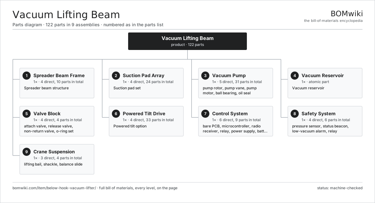
| # | Part | Qty | What it does |
|---|---|---|---|
| 1 | Spreader Beam Frame 4 parts | 1× | Spreader beam structure |
| 2 | Suction Pad Array 4 parts | 1× | Suction pad set |
| 3 | Vacuum Pump 5 parts | 1× | Rotary vane pump generating and holding the lifting vacuum. |
| 4 | Vacuum Reservoir | 1× | Vacuum reservoir |
| 5 | Valve Block 4 parts | 1× | Manifold sequencing attach, hold and release functions. |
| 6 | Powered Tilt Drive 4 parts | 1× | Powered tilt option |
| 7 | Control System 6 parts | 1× | Radio or pendant control sequencing the lift functions. |
| 8 | Safety System 4 parts | 1× | Vacuum monitoring and alarms to EN 13155 reserve factor. |
| 9 | Crane Suspension 3 parts | 1× | Balanced lifting bail hung from the crane hook. |
3D model
No 3D model yet. Have a CAD file of this? Add a 3D model — STL renders right on this page; STEP, FreeCAD, and OpenSCAD sources are welcome too (openly licensed, like all 3D models on BOMwiki).
Build & assembly graph
expand / collapse · shared sub-assemblies converge · links to related products · est. labourTap an assembly to expand/collapse · tap a part to open it · use “Open page” for any node · drag to pan, scroll to zoom.
Bill of materials for Vacuum Lifting Beam
9 top-level lines · 53 rows shown · 122 parts total · indented to 3 levels| # | Item / sub-assembly | Part no. | Qty/assy | Ext. qty | Parts | Type |
|---|---|---|---|---|---|---|
| 1 | Spreader Beam Frame 4 parts | below-hook-vacuum-lifter-beam-frame | 1× | 1 | 10 | assembly |
| 1.1 | Main Beam | below-hook-vacuum-lifter-main-beam | 1× | 1 | · | part |
| 1.2 | Telescoping Cross Arm | below-hook-vacuum-lifter-cross-arm | 2× | 2 | · | part |
| 1.3 | Pad Mount Bracket | below-hook-vacuum-lifter-pad-mount | 6× | 6 | · | part |
| 1.4 | Fastener Set | fastener-set | 1× | 1 | · | part |
| 2 | Suction Pad Array 4 parts | below-hook-vacuum-lifter-pad-array | 1× | 1 | 24 | assembly |
| 2.1 | Suction Pad | below-hook-vacuum-lifter-suction-pad | 6× | 6 | · | part |
| 2.2 | Pad Sealing Lip | below-hook-vacuum-lifter-pad-seal | 6× | 6 | · | part |
| 2.3 | Pad Vacuum Gauge | below-hook-vacuum-lifter-pad-gauge | 6× | 6 | · | part |
| 2.4 | Pad Isolating Valve | below-hook-vacuum-lifter-pad-valve | 6× | 6 | · | part |
| 3 | Vacuum Pump 5 parts | below-hook-vacuum-lifter-vacuum-pump | 1× | 1 | 31 | assembly |
| 3.1 | Pump Rotor | below-hook-vacuum-lifter-pump-rotor | 1× | 1 | · | part |
| 3.2 | Pump Vane | below-hook-vacuum-lifter-pump-vanes | 4× | 4 | · | part |
| 3.3 | Pump Motor 3 parts | below-hook-vacuum-lifter-pump-motor | 1× | 1 | 23 | assembly |
| 3.3.1 | Stator Assembly 3 parts + deeper › | stator-assembly | 1× | 1 | 3 | assembly |
| 3.3.2 | Rotor Assembly 4 parts + deeper › | rotor-assembly | 1× | 1 | 19 | assembly |
| 3.3.3 | Motor Housing | motor-housing | 1× | 1 | · | part |
| 3.4 | Ball Bearing | ball-bearing | 2× | 2 | · | part |
| 3.5 | Oil Seal | oil-seal | 1× | 1 | · | part |
| 4 | Vacuum Reservoir | below-hook-vacuum-lifter-reservoir | 1× | 1 | · | part |
| 5 | Valve Block 4 parts | below-hook-vacuum-lifter-valve-block | 1× | 1 | 4 | assembly |
| 5.1 | Attach Valve | below-hook-vacuum-lifter-attach-valve | 1× | 1 | · | part |
| 5.2 | Release Valve | below-hook-vacuum-lifter-release-valve | 1× | 1 | · | part |
| 5.3 | Non-Return Valve | below-hook-vacuum-lifter-check-valve | 1× | 1 | · | part |
| 5.4 | O-Ring Set | oring-set | 1× | 1 | · | part |
| 6 | Powered Tilt Drive 4 parts | below-hook-vacuum-lifter-tilt-drive | 1× | 1 | 33 | assembly |
| 6.1 | Tilt Motor 3 parts | below-hook-vacuum-lifter-tilt-motor | 1× | 1 | 23 | assembly |
| 6.1.1 | Stator Assembly 3 parts + deeper › | stator-assembly | 1× | 1 | 3 | assembly |
| 6.1.2 | Rotor Assembly 4 parts + deeper › | rotor-assembly | 1× | 1 | 19 | assembly |
| 6.1.3 | Motor Housing | motor-housing | 1× | 1 | · | part |
| 6.2 | Tilt Gearbox 4 parts | below-hook-vacuum-lifter-tilt-gearbox | 1× | 1 | 8 | assembly |
| 6.2.1 | Helical Gear Pair | gear-pair | 2× | 2 | · | part |
| 6.2.2 | Gearbox Housing | gearbox-housing | 1× | 1 | · | part |
| 6.2.3 | Ball Bearing | ball-bearing | 4× | 4 | · | part |
| 6.2.4 | Oil Seal | oil-seal | 1× | 1 | · | part |
| 6.3 | Tilt Pivot | below-hook-vacuum-lifter-tilt-pivot | 1× | 1 | · | part |
| 6.4 | Tilt Lock | below-hook-vacuum-lifter-tilt-lock | 1× | 1 | · | part |
| 7 | Control System 6 parts | below-hook-vacuum-lifter-control | 1× | 1 | 9 | assembly |
| 7.1 | Bare PCB | pcb-bare | 1× | 1 | · | part |
| 7.2 | Microcontroller | mcu | 1× | 1 | · | part |
| 7.3 | Radio Receiver | below-hook-vacuum-lifter-radio-receiver | 1× | 1 | · | part |
| 7.4 | Relay | relay | 4× | 4 | · | part |
| 7.5 | Power Supply | power-supply | 1× | 1 | · | part |
| 7.6 | Battery Pack | below-hook-vacuum-lifter-battery | 1× | 1 | · | part |
| 8 | Safety System 4 parts | below-hook-vacuum-lifter-safety-system | 1× | 1 | 6 | assembly |
| 8.1 | Pressure Sensor | pressure-sensor | 2× | 2 | · | part |
| 8.2 | Status Beacon | below-hook-vacuum-lifter-warning-light | 1× | 1 | · | part |
| 8.3 | Low-Vacuum Alarm | below-hook-vacuum-lifter-alarm | 1× | 1 | · | part |
| 8.4 | Relay | relay | 2× | 2 | · | part |
| 9 | Crane Suspension 3 parts | below-hook-vacuum-lifter-suspension | 1× | 1 | 4 | assembly |
| 9.1 | Lifting Bail | below-hook-vacuum-lifter-lifting-bail | 1× | 1 | · | part |
| 9.2 | Shackle | below-hook-vacuum-lifter-shackle | 2× | 2 | · | part |
| 9.3 | Balance Slide | below-hook-vacuum-lifter-balance-slide | 1× | 1 | · | part |
Related products
same domain, ranked by shared parts Articulated Forklift
2,417 parts · shares 4 with this page
Articulated Forklift
2,417 parts · shares 4 with this page
 Pallet Scissor Lift Table
196 parts · shares 4 with this page
Pallet Scissor Lift Table
196 parts · shares 4 with this page
 Pneumatic Conveying System
388 parts · shares 4 with this page
Pop-Up Wheel Sorter
705 parts · shares 4 with this page
Pneumatic Conveying System
388 parts · shares 4 with this page
Pop-Up Wheel Sorter
705 parts · shares 4 with this page
 Reach Truck
832 parts · shares 4 with this page
Vacuum Powder Conveyor
210 parts · shares 4 with this page
Reach Truck
832 parts · shares 4 with this page
Vacuum Powder Conveyor
210 parts · shares 4 with this page
Sourcing: possible vendors
Prices, MOQ, and lead times are algorithmic estimates, not quotes, and not claims about these companies. Company mappings are curated by keyword; est. price band $2k–$300k. How estimates work| Vendor | HQ | Specialty | MOQ | Lead time |
|---|---|---|---|---|
| toyota-industries.com ↗ | Kariya, JP | Forklifts & logistics | 20 units | 10–16 wks |
| kiongroup.com ↗ | Frankfurt, DE | Forklifts (Linde, STILL) | 20 units | 10–16 wks |
| jungheinrich.com ↗ | Hamburg, DE | Warehouse trucks | 20 units | 10–16 wks |
| crown.com ↗ | New Bremen, US | Forklifts | 20 units | 10–16 wks |
|
🇨🇳Hangcha
hcforklift.com ↗
|
Hangzhou, CN | Forklifts & material handling | 20 units | 10–16 wks |
967-word article