Sheerleg Floating Crane
ProductOverview
A sheerleg floating crane is a heavy-lift crane built onto a barge. Its lifting structure is a sheerleg: two raking legs joined at an apex to form an A-frame, with the hoist sheaves at the top. Unlike a revolving crane, the classic sheerleg does not slew. It lifts in a vertical plane fixed to the barge, and the load is positioned by moving the whole vessel with its mooring winches and by derricking the A-frame to change outreach.
This layout gives enormous capacity for the steel invested, because the A-frame carries load almost purely in compression down the legs and tension in the backstays. Sheerlegs handle the heaviest marine lifts: bridge sections, ship blocks, offshore jackets, harbour caissons and salvage. Capacities run from a few hundred tonnes on harbour units to several thousand tonnes on the largest vessels. Because the crane is non-revolving, the whole structure can be lighter and stiffer than an equivalent slewing crane of the same capacity.
Pontoon Hull
The Pontoon Hull provides buoyancy and the reaction base for the A-frame. Its Hull Plating Shell welded steel shell, in AH36 marine grade, encloses a hull divided by Watertight Bulkhead watertight bulkheads into ballast and void compartments. Heavy Main Deck Girder box girders run under the A-frame feet to spread the concentrated leg reactions into the hull.
Under tow, Directional Skeg skegs at the stern reduce yaw, and Sacrificial Anode sacrificial anodes protect the submerged steel from galvanic corrosion. The hull's stability is central to the crane: the lifting capacity is limited as much by how much the barge will heel as by the strength of the structure, which is why the ballast system is part of every lift plan.
Sheerleg A-Frame
The Sheerleg A-Frame is the lifting structure. Two Main Raking Leg raking legs, fabricated from S690 high-strength tube or box section and 30 to 90 m long, rise from foot pivots on the deck to meet at the Apex Sheave Head. The apex carries Apex Load Sheave cast-steel sheaves up to 2 m in diameter that reeve the main hoist rope. Leg Cross-Bracing cross-braces tie the legs together against out-of-plane buckling.
Each leg foot turns on a Leg Foot Pivot Pin hardened pivot pin so the A-frame can derrick fore and aft. Raking the legs forward increases outreach beyond the bow; raking them back brings the hook inboard. The whole frame is sized so the legs stay in compression and the backstays in tension through the full derricking range.
Derricking System
The Derricking System system sets the rake of the A-frame and so the outreach of the hook. Backstay Member adjustable ties run from the apex back to the stern, and the Derricking Winch hauls or pays the backstay tackle to move the apex through an arc. That winch uses a Derricking Rope Drum drum, a Helical Gear Pair reduction, a Derricking Drive Motor drive motor and Ball Bearing bearings, reeving Derricking Wire Rope wire rope over Backstay Sheave backstay sheaves.
Because derricking changes both outreach and lift height, the lift plan tabulates capacity against outreach the same way a land crane uses a load chart.
Hoist System
The Hoist System carries two independent hoists. The Main Hoist Winch handles the rated load slowly and steadily: a large Main Hoist Drum drum, two Helical Gear Pair reduction stages, two Main Hoist Motor VFD-driven motors for fine control and two Main Hoist Brake spring-applied holding brakes. The rope is Main Hoist Wire Rope rotation-resistant wire reeved through a Main Hook Block hook block with eight to sixteen falls.
The Auxiliary Hoist Winch is faster and lighter for small loads and precise placement, with its own Auxiliary Drum, Helical Gear Pair reduction, Auxiliary Hoist Motor motor and Auxiliary Hook hook. During a lift the auxiliary hoist often trims the attitude of a load that the main hoist carries.
Ballast and Power
The Ballast & Trim System is what makes a heavy lift possible. As the hook takes load, the barge tries to trim forward; Ballast Pump pumps move water between tanks through Ballast Isolation Valve valves and Ballast Pipework pipework to hold the deck level, with Tank Level Gauge gauges reporting every tank. The operator pre-ballasts before the pick, then trims continuously through the lift.
Everything is fed by the Diesel-Electric Power Plant. Two Diesel Generator Set diesel generator sets supply a Main Switchboard main switchboard, a Distribution Transformer feeds the services, a Day Fuel Tank day tank holds fuel, and Wire Bundle cabling links the drives. Diesel-electric power suits the duty: long idle periods punctuated by short high-power hoisting.
Mooring and Control
The non-revolving sheerleg positions a load by moving the whole barge, so the Mooring & Positioning Gear gear is integral to the crane. Four to eight Mooring Winch winches haul Mooring Wire & Chain combination wire-and-chain legs through Roller Fairlead fairleads to High-Holding Anchor anchors set in a spread. By paying one line and hauling another, the lift master walks the barge sideways or fore and aft to spot the load.
The lift is run from the Lift Control Room. A Operator Control Desk console gives the lift master hoist, derrick and ballast control; a Load Monitoring System shows rope tension and total load; an Heel & Trim Sensor reports heel and trim to the ballast logic; a Crane Control PLC PLC coordinates the functions; and two LCD Panel displays present the lift status. Operating wind limits are low, 12 to 16 m/s, because a suspended heavy load on a floating base is sensitive to wind and wave motion.
Sheerleg Floating Crane parts and their functions
8 top-level parts · 104 parts in total · full bill of materials below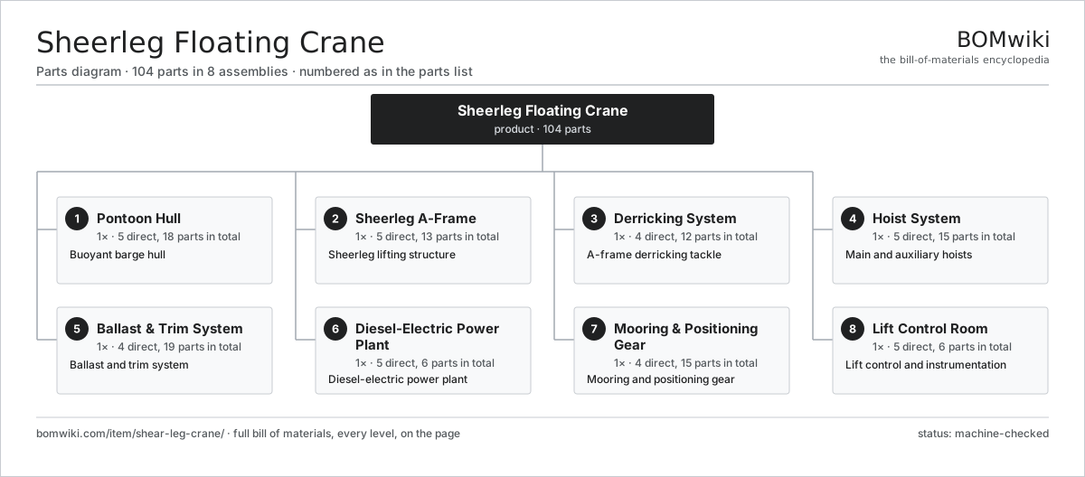
| # | Part | Qty | What it does |
|---|---|---|---|
| 1 | Pontoon Hull 5 parts | 1× | Buoyant barge hull |
| 2 | Sheerleg A-Frame 5 parts | 1× | Sheerleg lifting structure |
| 3 | Derricking System 4 parts | 1× | A-frame derricking tackle |
| 4 | Hoist System 5 parts | 1× | Main and auxiliary hoists |
| 5 | Ballast & Trim System 4 parts | 1× | Ballast and trim system |
| 6 | Diesel-Electric Power Plant 5 parts | 1× | Diesel-electric power plant |
| 7 | Mooring & Positioning Gear 4 parts | 1× | Mooring and positioning gear |
| 8 | Lift Control Room 5 parts | 1× | Lift control and instrumentation |
3D model
No 3D model yet. Have a CAD file of this? Add a 3D model — STL renders right on this page; STEP, FreeCAD, and OpenSCAD sources are welcome too (openly licensed, like all 3D models on BOMwiki).
Build & assembly graph
expand / collapse · shared sub-assemblies converge · links to related products · est. labourTap an assembly to expand/collapse · tap a part to open it · use “Open page” for any node · drag to pan, scroll to zoom.
Bill of materials for Sheerleg Floating Crane
8 top-level lines · 57 rows shown · 104 parts total · indented to 3 levels| # | Item / sub-assembly | Part no. | Qty/assy | Ext. qty | Parts | Type |
|---|---|---|---|---|---|---|
| 1 | Pontoon Hull 5 parts | shear-leg-crane-pontoon | 1× | 1 | 18 | assembly |
| 1.1 | Hull Plating Shell | shear-leg-crane-hull-plating | 1× | 1 | · | part |
| 1.2 | Watertight Bulkhead | shear-leg-crane-bulkhead | 8× | 8 | · | part |
| 1.3 | Main Deck Girder | shear-leg-crane-deck-girder | 6× | 6 | · | part |
| 1.4 | Directional Skeg | shear-leg-crane-skeg | 2× | 2 | · | part |
| 1.5 | Sacrificial Anode | shear-leg-crane-anode | 1× | 1 | · | part |
| 2 | Sheerleg A-Frame 5 parts | shear-leg-crane-a-frame | 1× | 1 | 13 | assembly |
| 2.1 | Main Raking Leg | shear-leg-crane-main-leg | 2× | 2 | · | part |
| 2.2 | Apex Sheave Head | shear-leg-crane-apex-head | 1× | 1 | · | part |
| 2.3 | Leg Cross-Bracing | shear-leg-crane-leg-bracing | 4× | 4 | · | part |
| 2.4 | Leg Foot Pivot Pin | shear-leg-crane-leg-pin | 2× | 2 | · | part |
| 2.5 | Apex Load Sheave | shear-leg-crane-apex-sheave | 4× | 4 | · | part |
| 3 | Derricking System 4 parts | shear-leg-crane-derricking | 1× | 1 | 12 | assembly |
| 3.1 | Backstay Member | shear-leg-crane-backstay | 2× | 2 | · | part |
| 3.2 | Derricking Winch 4 parts | shear-leg-crane-derrick-winch | 1× | 1 | 5 | assembly |
| 3.2.1 | Derricking Rope Drum | shear-leg-crane-derrick-drum | 1× | 1 | · | part |
| 3.2.2 | Helical Gear Pair | gear-pair | 1× | 1 | · | part |
| 3.2.3 | Derricking Drive Motor | shear-leg-crane-derrick-motor | 1× | 1 | · | part |
| 3.2.4 | Ball Bearing | ball-bearing | 2× | 2 | · | part |
| 3.3 | Derricking Wire Rope | shear-leg-crane-derrick-rope | 1× | 1 | · | part |
| 3.4 | Backstay Sheave | shear-leg-crane-derrick-sheave | 4× | 4 | · | part |
| 4 | Hoist System 5 parts | shear-leg-crane-hoist-system | 1× | 1 | 15 | assembly |
| 4.1 | Main Hoist Winch 5 parts | shear-leg-crane-main-winch | 1× | 1 | 9 | assembly |
| 4.1.1 | Main Hoist Drum | shear-leg-crane-main-drum | 1× | 1 | · | part |
| 4.1.2 | Helical Gear Pair | gear-pair | 2× | 2 | · | part |
| 4.1.3 | Main Hoist Motor | shear-leg-crane-main-motor | 2× | 2 | · | part |
| 4.1.4 | Main Hoist Brake | shear-leg-crane-main-brake | 2× | 2 | · | part |
| 4.1.5 | Ball Bearing | ball-bearing | 2× | 2 | · | part |
| 4.2 | Auxiliary Hoist Winch 3 parts | shear-leg-crane-aux-winch | 1× | 1 | 3 | assembly |
| 4.2.1 | Auxiliary Drum | shear-leg-crane-aux-drum | 1× | 1 | · | part |
| 4.2.2 | Helical Gear Pair | gear-pair | 1× | 1 | · | part |
| 4.2.3 | Auxiliary Hoist Motor | shear-leg-crane-aux-motor | 1× | 1 | · | part |
| 4.3 | Main Hoist Wire Rope | shear-leg-crane-main-rope | 1× | 1 | · | part |
| 4.4 | Main Hook Block | shear-leg-crane-main-block | 1× | 1 | · | part |
| 4.5 | Auxiliary Hook | shear-leg-crane-aux-hook | 1× | 1 | · | part |
| 5 | Ballast & Trim System 4 parts | shear-leg-crane-ballast-system | 1× | 1 | 19 | assembly |
| 5.1 | Ballast Pump | shear-leg-crane-ballast-pump | 2× | 2 | · | part |
| 5.2 | Ballast Isolation Valve | shear-leg-crane-ballast-valve | 8× | 8 | · | part |
| 5.3 | Ballast Pipework | shear-leg-crane-ballast-pipe | 1× | 1 | · | part |
| 5.4 | Tank Level Gauge | shear-leg-crane-tank-gauge | 8× | 8 | · | part |
| 6 | Diesel-Electric Power Plant 5 parts | shear-leg-crane-power-plant | 1× | 1 | 6 | assembly |
| 6.1 | Diesel Generator Set | shear-leg-crane-genset | 2× | 2 | · | part |
| 6.2 | Main Switchboard | shear-leg-crane-switchboard | 1× | 1 | · | part |
| 6.3 | Distribution Transformer | shear-leg-crane-transformer | 1× | 1 | · | part |
| 6.4 | Day Fuel Tank | shear-leg-crane-fuel-tank | 1× | 1 | · | part |
| 6.5 | Wire Bundle | wire-bundle | 1× | 1 | · | part |
| 7 | Mooring & Positioning Gear 4 parts | shear-leg-crane-mooring | 1× | 1 | 15 | assembly |
| 7.1 | Mooring Winch | shear-leg-crane-mooring-winch | 4× | 4 | · | part |
| 7.2 | High-Holding Anchor | shear-leg-crane-anchor | 4× | 4 | · | part |
| 7.3 | Roller Fairlead | shear-leg-crane-fairlead | 6× | 6 | · | part |
| 7.4 | Mooring Wire & Chain | shear-leg-crane-mooring-rope | 1× | 1 | · | part |
| 8 | Lift Control Room 5 parts | shear-leg-crane-control-room | 1× | 1 | 6 | assembly |
| 8.1 | Operator Control Desk | shear-leg-crane-control-desk | 1× | 1 | · | part |
| 8.2 | Load Monitoring System | shear-leg-crane-load-monitor | 1× | 1 | · | part |
| 8.3 | Heel & Trim Sensor | shear-leg-crane-inclinometer | 1× | 1 | · | part |
| 8.4 | Crane Control PLC | shear-leg-crane-plc | 1× | 1 | · | part |
| 8.5 | LCD Panel | lcd-panel | 2× | 2 | · | part |
Related products
same domain, ranked by shared parts Articulated Forklift
2,417 parts · shares 1 with this page
AS/RS Stacker Crane
276 parts · shares 1 with this page
Articulated Forklift
2,417 parts · shares 1 with this page
AS/RS Stacker Crane
276 parts · shares 1 with this page
 Automated Guided Cart (AGV)
749 parts · shares 1 with this page
Automated Guided Cart (AGV)
749 parts · shares 1 with this page
 Bag Palletizer
951 parts · shares 1 with this page
Bulk Bag Discharger
178 parts · shares 1 with this page
Coal Yard Stacker
571 parts · shares 1 with this page
Bag Palletizer
951 parts · shares 1 with this page
Bulk Bag Discharger
178 parts · shares 1 with this page
Coal Yard Stacker
571 parts · shares 1 with this page
Sourcing: possible vendors
Prices, MOQ, and lead times are algorithmic estimates, not quotes, and not claims about these companies. Company mappings are curated by keyword; est. price band $2k–$300k. How estimates work| Vendor | HQ | Specialty | MOQ | Lead time |
|---|---|---|---|---|
| toyota-industries.com ↗ | Kariya, JP | Forklifts & logistics | 20 units | 10–16 wks |
| kiongroup.com ↗ | Frankfurt, DE | Forklifts (Linde, STILL) | 20 units | 10–16 wks |
| jungheinrich.com ↗ | Hamburg, DE | Warehouse trucks | 20 units | 10–16 wks |
| crown.com ↗ | New Bremen, US | Forklifts | 20 units | 10–16 wks |
|
🇨🇳Hangcha
hcforklift.com ↗
|
Hangzhou, CN | Forklifts & material handling | 20 units | 10–16 wks |
1,048-word article