Container Handler
ProductOverview
A container handler is a forklift scaled up to lift loaded shipping containers, the kind that weigh forty tonnes and must be stacked four or five high in a port or rail yard. It is not a forklift with bigger forks: the load is gripped from above by a spreader that locks into the container's corner castings, and the whole machine is sized around the moment of holding that load out past its front wheels. Ports, inland terminals, and large depots use these to move and stack full containers where a gantry crane is not justified. The machine is built from a heavy diesel Powertrain, a Mast Assembly, a Container Spreader, a high-flow Hydraulic System, a massive Chassis Frame, a heavy Axle System, an elevated Operator Cab, and a Electrical System that weighs and sequences the load.
Powertrain
The Powertrain starts with a Diesel Engine, typically a six-cylinder turbo diesel near 9 L producing over 200 kW, because lifting forty tonnes and moving a sixty-tonne machine needs real power. It drives a Torque Converter that multiplies torque at low speed so the loaded truck can move off and climb yard ramps without stalling, then a Powershift Transmission powershift gearbox that shifts forward and reverse under load. With heavy Clutch Pack packs sized for the torque, a single Driveshaft carries drive to the front axle, which is the only driven axle because nearly all the weight rides over it when a container is on the spreader.
Mast and lifting
The Mast Assembly is a heavy two-stage mast. Twin Lift Cylinder rams and four Lift Chain chains raise the spreader, large Mast Roller rollers carry the side loads, and Tilt Cylinder rams tilt the mast to align and cradle the container. Everything is overbuilt compared to a warehouse forklift because the load is an order of magnitude heavier and is lifted to the top of a four- or five-high stack, where any flex or misalignment would make seating the container difficult.
The spreader
The Container Spreader is the attachment that makes this a container machine. It is a telescoping frame: Telescope Cylinder rams extend the Spreader Frame arms to match a 20 ft or 40 ft container so one truck handles both common sizes. At each corner a Twistlock drops into the container's corner casting, and a Twistlock Cylinder rotates the Twistlock Cone a quarter turn to lock it, the same interface a ship's crane uses. Guide Flipper guide arms funnel the spreader onto the corners as it lands, a Spreader Rotator side-shifts and rotates the spreader to square up with a skewed container, and Landing Sensor sensors confirm the spreader is seated and the locks are engaged before the operator lifts. That interlock matters: lifting before all four locks are confirmed would drop the container.
Hydraulics
The Hydraulic System is high-flow because the heavy mast and spreader need a lot of oil quickly. A Load-Sensing Pump load-sensing pump supplies the Control Valve Bank bank, whose Valve Spool spools are shifted by Pilot Solenoid pilots from the cab joysticks, with a Relief Valve capping pressure. A Oil Cooler is in the loop because moving this much oil under load heats it, and the Hydraulic Filter and Hydraulic Reservoir keep it clean and supplied. Stiff Hydraulic Hose runs feed the mast and the spreader.
Chassis, counterweight, and axles
The Main Frame is a massive welded box, and the defining number is the Counterweight: balancing a forty-tonne container held out ahead of the front wheels takes an enormous cast counterweight at the rear, which is why the empty machine weighs around sixty tonnes. The Axle System reflects that load. The front Drive Axle runs dual Heavy Tire tires and carries a Differential with planetary Final Drive hub reductions, the rear Steer Axle is steered by twin Steer Cylinder cylinders, and Wet Disc Brake oil-cooled discs handle the braking energy of a heavy truck.
Cab, controls, and load system
The Operator Cab sits high and on a Cab Slide that shifts it sideways, because the operator must see the top of a container several units up and align the spreader precisely. Two Joystick joysticks run the lift, tilt, and spreader functions, and a Operator Display shows the load weight, spreader status, and camera views. The Electrical System carries a Load Controller that reads Load Cell sensors to weigh the container, sequences the twistlocks, and guards against an overload or an unbalanced lift, with Camera views covering blind spots around the long machine.
Variants and use
Loaded handlers like this stack full containers; a related machine, the empty-container handler, uses a lighter top-lift or side-grab spreader for stacking empties higher and faster. Reach stackers add a telescopic boom to reach over a row of containers and place them in the second or third row of a stack, trading some capacity for reach. The buyers are ports, intermodal rail terminals, and container depots that need to move and stack full containers without the fixed infrastructure of a gantry crane.
Container Handler parts and their functions
8 top-level parts · 552 parts in total · full bill of materials below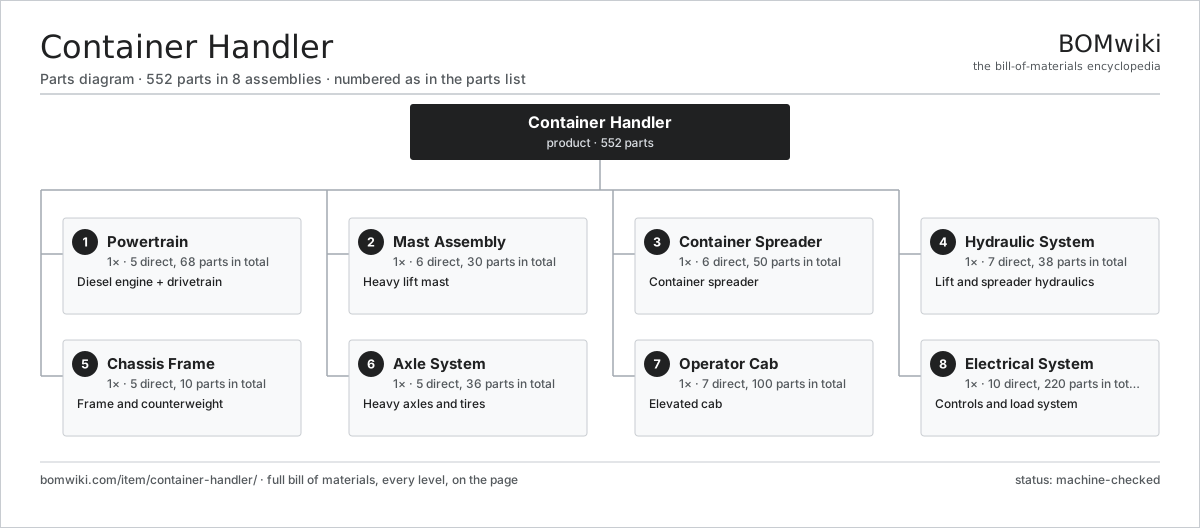
| # | Part | Qty | What it does |
|---|---|---|---|
| 1 | Powertrain 5 parts | 1× | Diesel engine + drivetrain |
| 2 | Mast Assembly 6 parts | 1× | Heavy lift mast |
| 3 | Container Spreader 6 parts | 1× | Container spreader |
| 4 | Hydraulic System 7 parts | 1× | Lift and spreader hydraulics |
| 5 | Chassis Frame 5 parts | 1× | Frame and counterweight |
| 6 | Axle System 5 parts | 1× | Heavy axles and tires |
| 7 | Operator Cab 7 parts | 1× | Elevated cab |
| 8 | Electrical System 10 parts | 1× | Controls and load system |
3D model
No 3D model yet. Have a CAD file of this? Add a 3D model — STL renders right on this page; STEP, FreeCAD, and OpenSCAD sources are welcome too (openly licensed, like all 3D models on BOMwiki).
Build & assembly graph
expand / collapse · shared sub-assemblies converge · links to related products · est. labourTap an assembly to expand/collapse · tap a part to open it · use “Open page” for any node · drag to pan, scroll to zoom.
Bill of materials for Container Handler
8 top-level lines · 103 rows shown · 552 parts total · indented to 3 levels| # | Item / sub-assembly | Part no. | Qty/assy | Ext. qty | Parts | Type |
|---|---|---|---|---|---|---|
| 1 | Powertrain 5 parts | ch-powertrain | 1× | 1 | 68 | assembly |
| 1.1 | Diesel Engine 9 parts | ch-diesel-engine | 1× | 1 | 44 | assembly |
| 1.1.1 | Cylinder Block | ch-engine-block | 1× | 1 | · | part |
| 1.1.2 | Cylinder Head 3 parts + deeper › | ch-cylinder-head | 1× | 1 | 25 | assembly |
| 1.1.3 | Piston Assembly | rtf-piston-set | 6× | 6 | · | part |
| 1.1.4 | Crankshaft | ch-crankshaft | 1× | 1 | · | part |
| 1.1.5 | Turbocharger | rtf-turbocharger | 2× | 2 | · | part |
| 1.1.6 | Injection Pump | rtf-injection-pump | 1× | 1 | · | part |
| 1.1.7 | Radiator Pack | ch-radiator | 1× | 1 | · | part |
| 1.1.8 | Oil Seal | oil-seal | 6× | 6 | · | part |
| 1.1.9 | Fastener Set | fastener-set | 1× | 1 | · | part |
| 1.2 | Torque Converter | rtf-torque-converter | 1× | 1 | · | part |
| 1.3 | Powershift Transmission 5 parts | ch-transmission | 1× | 1 | 21 | assembly |
| 1.3.1 | Clutch Pack | rtf-clutch-pack | 4× | 4 | · | part |
| 1.3.2 | Helical Gear Pair | gear-pair | 4× | 4 | · | part |
| 1.3.3 | Gearbox Housing | gearbox-housing | 1× | 1 | · | part |
| 1.3.4 | Ball Bearing | ball-bearing | 8× | 8 | · | part |
| 1.3.5 | Oil Seal | oil-seal | 4× | 4 | · | part |
| 1.4 | Driveshaft | rtf-driveshaft | 1× | 1 | · | part |
| 1.5 | Fuel Tank | ch-fuel-tank | 1× | 1 | · | part |
| 2 | Mast Assembly 6 parts | ch-mast-assembly | 1× | 1 | 30 | assembly |
| 2.1 | Outer Mast Section | ch-mast-outer | 2× | 2 | · | part |
| 2.2 | Inner Mast Section | ch-mast-inner | 2× | 2 | · | part |
| 2.3 | Lift Cylinder 4 parts | ch-lift-cylinder | 2× | 2 | 4 | assembly |
| 2.3.1 | Cylinder Barrel | ch-cylinder-barrel | 1× | 2 | · | part |
| 2.3.2 | Piston Rod | ch-piston-rod | 1× | 2 | · | part |
| 2.3.3 | O-Ring Set | oring-set | 1× | 2 | · | part |
| 2.3.4 | Rod Seal | rtf-rod-seal | 1× | 2 | · | part |
| 2.4 | Lift Chain | ch-lift-chain | 4× | 4 | · | part |
| 2.5 | Mast Roller | ch-mast-roller | 12× | 12 | · | part |
| 2.6 | Tilt Cylinder | ch-tilt-cylinder | 2× | 2 | · | part |
| 3 | Container Spreader 6 parts | ch-spreader | 1× | 1 | 50 | assembly |
| 3.1 | Spreader Frame | ch-spreader-frame | 1× | 1 | · | part |
| 3.2 | Telescope Cylinder | ch-telescope-cylinder | 2× | 2 | · | part |
| 3.3 | Twistlock 3 parts | ch-twistlock | 4× | 4 | 3 | assembly |
| 3.3.1 | Twistlock Cone | ch-twistlock-cone | 1× | 4 | · | part |
| 3.3.2 | Twistlock Cylinder | ch-twistlock-cylinder | 1× | 4 | · | part |
| 3.3.3 | Landing Sensor | ch-landing-sensor | 1× | 4 | · | part |
| 3.4 | Guide Flipper | ch-flipper | 4× | 4 | · | part |
| 3.5 | Spreader Rotator 3 parts | ch-spreader-rotator | 1× | 1 | 27 | assembly |
| 3.5.1 | Servo Motor 4 parts + deeper › | servo-motor | 1× | 1 | 24 | assembly |
| 3.5.2 | Helical Gear Pair | gear-pair | 1× | 1 | · | part |
| 3.5.3 | Ball Bearing | ball-bearing | 2× | 2 | · | part |
| 3.6 | Landing Sensor | ch-landing-sensor | 4× | 4 | · | part |
| 4 | Hydraulic System 7 parts | ch-hydraulic-system | 1× | 1 | 38 | assembly |
| 4.1 | Load-Sensing Pump | ch-hydraulic-pump | 1× | 1 | · | part |
| 4.2 | Control Valve Bank 4 parts | ch-control-valve | 1× | 1 | 14 | assembly |
| 4.2.1 | Valve Spool | rtf-valve-spool | 6× | 6 | · | part |
| 4.2.2 | Pilot Solenoid | th-solenoid | 6× | 6 | · | part |
| 4.2.3 | Relief Valve | rtf-relief-valve | 1× | 1 | · | part |
| 4.2.4 | O-Ring Set | oring-set | 1× | 1 | · | part |
| 4.3 | Hydraulic Reservoir | ch-hydraulic-tank | 1× | 1 | · | part |
| 4.4 | Oil Cooler | ch-oil-cooler | 1× | 1 | · | part |
| 4.5 | Hydraulic Filter | rtf-hydraulic-filter | 1× | 1 | · | part |
| 4.6 | Hydraulic Hose | rtf-hydraulic-hose | 16× | 16 | · | part |
| 4.7 | Pressure Sensor | pressure-sensor | 4× | 4 | · | part |
| 5 | Chassis Frame 5 parts | ch-chassis-frame | 1× | 1 | 10 | assembly |
| 5.1 | Main Frame | ch-main-frame | 1× | 1 | · | part |
| 5.2 | Counterweight | ch-counterweight | 1× | 1 | · | part |
| 5.3 | Engine Hood | ch-engine-hood | 1× | 1 | · | part |
| 5.4 | Sheet Metal Panel | sheet-panel | 6× | 6 | · | part |
| 5.5 | Fastener Set | fastener-set | 1× | 1 | · | part |
| 6 | Axle System 5 parts | ch-axle-system | 1× | 1 | 36 | assembly |
| 6.1 | Drive Axle 4 parts | ch-drive-axle | 1× | 1 | 11 | assembly |
| 6.1.1 | Differential | rtf-differential | 1× | 1 | · | part |
| 6.1.2 | Final Drive | rtf-final-drive | 2× | 2 | · | part |
| 6.1.3 | Ball Bearing | ball-bearing | 4× | 4 | · | part |
| 6.1.4 | Oil Seal | oil-seal | 4× | 4 | · | part |
| 6.2 | Steer Axle 4 parts | ch-steer-axle | 1× | 1 | 7 | assembly |
| 6.2.1 | Steering Knuckle | rtf-steer-knuckle | 2× | 2 | · | part |
| 6.2.2 | Steer Cylinder | rtf-steer-cylinder | 2× | 2 | · | part |
| 6.2.3 | Tie Rod | rtf-tie-rod | 1× | 1 | · | part |
| 6.2.4 | Ball Bearing | ball-bearing | 2× | 2 | · | part |
| 6.3 | Heavy Tire | ch-tire | 8× | 8 | · | part |
| 6.4 | Wheel Rim | ch-wheel-rim | 8× | 8 | · | part |
| 6.5 | Wet Disc Brake | ch-wet-brake | 2× | 2 | · | part |
| 7 | Operator Cab 7 parts | ch-operator-cab | 1× | 1 | 100 | assembly |
| 7.1 | Cab Frame | ch-cab-frame | 1× | 1 | · | part |
| 7.2 | Operator Seat | rtf-operator-seat | 1× | 1 | · | part |
| 7.3 | Joystick | th-joystick | 2× | 2 | · | part |
| 7.4 | Steering Column | rtf-steering-column | 1× | 1 | · | part |
| 7.5 | Pedal Set | rtf-pedal-set | 1× | 1 | · | part |
| 7.6 | Operator Display 4 parts | ch-cab-display | 1× | 1 | 93 | assembly |
| 7.6.1 | Bare PCB | pcb-bare | 1× | 1 | · | part |
| 7.6.2 | Microcontroller | mcu | 1× | 1 | · | part |
| 7.6.3 | LCD Panel | lcd-panel | 1× | 1 | · | part |
| 7.6.4 | SMD Passive (R/C/L) | smd-passives | 90× | 90 | · | part |
| 7.7 | Cab Slide | ch-cab-slide | 1× | 1 | · | part |
| 8 | Electrical System 10 parts | ch-electrical-system | 1× | 1 | 220 | assembly |
| 8.1 | Battery | rtf-battery | 2× | 2 | · | part |
| 8.2 | Alternator | rtf-alternator | 1× | 1 | · | part |
| 8.3 | Starter Motor | rtf-starter-motor | 1× | 1 | · | part |
| 8.4 | Load Controller 4 parts | ch-load-controller | 1× | 1 | 144 | assembly |
| 8.4.1 | Bare PCB | pcb-bare | 1× | 1 | · | part |
| 8.4.2 | Microcontroller | mcu | 1× | 1 | · | part |
| 8.4.3 | CAN Transceiver | can-transceiver | 2× | 2 | · | part |
| 8.4.4 | SMD Passive (R/C/L) | smd-passives | 140× | 140 | · | part |
| 8.5 | Load Cell | ch-load-cell | 2× | 2 | · | part |
| 8.6 | Camera | ch-camera | 3× | 3 | · | part |
| 8.7 | Work Light | rtf-work-light | 6× | 6 | · | part |
| 8.8 | Wire Bundle | wire-bundle | 1× | 1 | · | part |
| 8.9 | Relay | relay | 12× | 12 | · | part |
| 8.10 | Connector | connector | 48× | 48 | · | part |
Related products
same domain, ranked by shared parts Telescopic Handler
380 parts · shares 31 with this page
Telescopic Handler
380 parts · shares 31 with this page
 Rough-Terrain Forklift
247 parts · shares 30 with this page
Order Picker
708 parts · shares 9 with this page
Walkie Stacker
541 parts · shares 7 with this page
Rough-Terrain Forklift
247 parts · shares 30 with this page
Order Picker
708 parts · shares 9 with this page
Walkie Stacker
541 parts · shares 7 with this page
 Reach Truck
832 parts · shares 9 with this page
Turret Truck
664 parts · shares 9 with this page
Reach Truck
832 parts · shares 9 with this page
Turret Truck
664 parts · shares 9 with this page
Sourcing: possible vendors
Prices, MOQ, and lead times are algorithmic estimates, not quotes, and not claims about these companies. Company mappings are curated by keyword; est. price band $2k–$300k. How estimates work| Vendor | HQ | Specialty | MOQ | Lead time |
|---|---|---|---|---|
| toyota-industries.com ↗ | Kariya, JP | Forklifts & logistics | 20 units | 10–16 wks |
| kiongroup.com ↗ | Frankfurt, DE | Forklifts (Linde, STILL) | 20 units | 10–16 wks |
| jungheinrich.com ↗ | Hamburg, DE | Warehouse trucks | 20 units | 10–16 wks |
| crown.com ↗ | New Bremen, US | Forklifts | 20 units | 10–16 wks |
|
🇨🇳Hangcha
hcforklift.com ↗
|
Hangzhou, CN | Forklifts & material handling | 20 units | 10–16 wks |
897-word article