Pedestal Deck Crane
ProductOverview
A pedestal deck crane is a slewing crane mounted on a fixed vertical column rather than a travelling carriage. The pedestal is bolted or welded to a deck, jetty head, quay or platform, and the whole crane rotates on a large slew bearing at the top of that column. This arrangement suits sites where the lifting position is fixed but the load must be picked from and placed across a wide arc: cargo holds, supply boats alongside a platform, barges at a jetty, or stores on a deck.
The crane handles loads from a few tonnes on small harbour units up to 150 t on heavy offshore cranes. Radius typically runs from 6 to 40 m, and the boom luffs (raises and lowers) to set that radius while the machinery house slews continuously through 360 degrees. Because the load capacity falls as radius grows, the operator works to a load chart that the Control & Cab System enforces electronically.
Pedestal and Foundation
The Support Pedestal carries every load the crane generates: the dead weight of the rotating mass, the load moment, and the overturning moment from wind and dynamic swing. It is a rolled and welded steel cylinder, 1.2 to 2.5 m in diameter with a 20 to 40 mm wall, built from Pedestal Column Tube plate in S355 grade. Internal Internal Stiffener Ring diaphragms stop the tube ovalising where bending peaks, usually just below the slew bearing.
At its foot the Base Mounting Flange spreads the load into the deck or concrete foundation through 24 to 48 high-tensile bolts from the Fastener Set. An Internal Access Ladder runs up inside the column so a technician can reach the slew bearing and the underside of the rotating deck without external scaffolding.
Slewing System
The Slewing System sits on top of the pedestal. Its heart is the Slew Ring Bearing, a three-row roller slew ring 1.5 to 3 m in pitch diameter that takes axial, radial and moment loads simultaneously and carries internal gear teeth on its bore. Two Slew Drive Pinion pinions, each driven through a Helical Gearbox planetary reducer and a Hydraulic Slew Motor hydraulic motor, mesh with those teeth to turn the deck.
Each gearbox uses a Gearbox Housing casting, Helical Gear Pair planetary stages, Ball Bearing support bearings and Oil Seal shaft seals, giving a 60 to 120:1 reduction. A Slew Parking Brake spring-applied brake on each motor holds the deck against wind and list when slewing is not commanded, which matters on a heeling vessel or an exposed jetty.
Rotating Machinery House
The Rotating Machinery House is everything that turns. Its Rotating Structural Deck box-girder turntable bolts to the upper race of the slew ring and carries the winches, power unit and counterweight. A Machinery House Shell insulated enclosure keeps spray and weather off the hydraulics. At the rear a Counterweight Block block of 3 to 25 t balances the boom and load moment so the slew bearing is not overloaded on the back-reach.
The boom heel pivots on two Boom Heel Pivot Pin hardened pins running in self-lubricating bushes. These pins carry the full luffing reaction and are sized for the fatigue life of the crane, since they cycle on every lift.
Boom and Lifting Tackle
The Luffing Boom is a luffing boom built up from a Boom Heel Section heel section, one or more Lattice Insert Section lattice bays that set the length, and a Boom Tip Section head section carrying the Boom Tip Sheave rope sheaves. Lattice booms keep weight down for long reach; box booms are stiffer for heavy short-radius work. The boom is held by Luffing Pendant Bar forged pendant bars that transmit luffing force from the gantry to the boom point.
The lifting tackle is the Hook & Rope Rigging. Rotation-resistant Hoist Wire Rope runs from the hoist drum over the boom sheaves and reeves through a Hook Block hook block to give two to eight falls. The load hangs on a forged Safety Lifting Hook with a spring safety latch, and a Overhaul Ball keeps the rope taut on light single-fall lifts.
Winches and Hydraulic Power
Two winches do the work. The Main Hoist Winch raises the load: a Lebus-grooved Hoist Rope Drum, a Helical Gear Pair reduction, a Hoist Hydraulic Motor hydraulic motor and a fail-safe Hoist Holding Brake that clamps the moment hydraulic pressure is lost. The Luffing Winch raises and lowers the boom through its own Luffing Rope Drum, Luffing Hydraulic Motor and Luffing Holding Brake.
All of this is fed by the Hydraulic Power Unit unit. Two load-sensing Variable Axial-Piston Pump piston pumps, driven by a Pump Drive Motor or a diesel engine, draw from a baffled Hydraulic Reservoir and feed a Directional Valve Block proportional manifold. An Oil Cooler holds oil temperature below 60 deg C, and O-Ring Set seals close the circuit. Load-sensing control means the pumps only deliver the flow a given motion demands, which cuts heat and fuel during the long idle periods typical of cargo work.
Controls and Safe Operation
The operator sits in the Operator Cab, a heated glazed cab with a roof window for hook visibility. Two Proportional Joystick Hall-effect joysticks command hoist, luff and slew through a safety-rated Crane Control PLC. A Load Measuring Cell measures rope tension and a Wind Speed Sensor at the boom tip reads wind speed; both feed the rated-capacity limiter shown on the LCD Panel display.
The limiter compares measured load and radius against the stored chart and stops any motion that would exceed the safe working load, and it cuts crane operation when wind passes the in-service limit, typically 20 to 24 m/s. Cranes built to EN 13852 or DNV offshore rules add dynamic factors for vessel motion and a constant-tension or active heave function so a load can be set on a moving boat without snatch loading the rope.
Pedestal Deck Crane parts and their functions
9 top-level parts · 75 parts in total · full bill of materials below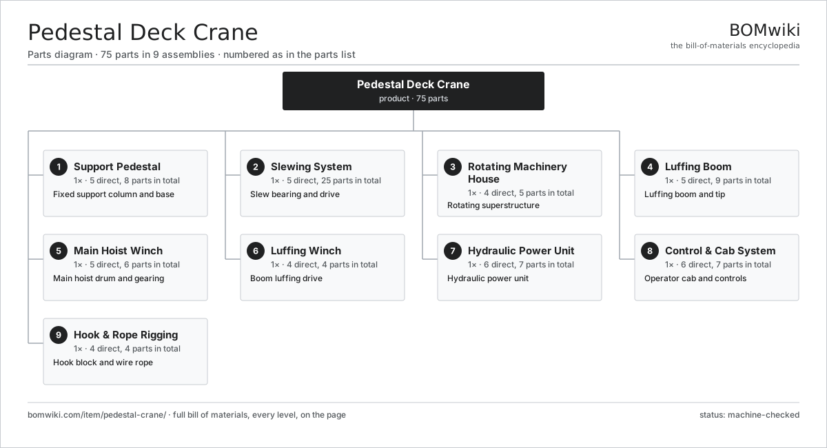
| # | Part | Qty | What it does |
|---|---|---|---|
| 1 | Support Pedestal 5 parts | 1× | Fixed support column and base |
| 2 | Slewing System 5 parts | 1× | Slew bearing and drive |
| 3 | Rotating Machinery House 4 parts | 1× | Rotating superstructure |
| 4 | Luffing Boom 5 parts | 1× | Luffing boom and tip |
| 5 | Main Hoist Winch 5 parts | 1× | Main hoist drum and gearing |
| 6 | Luffing Winch 4 parts | 1× | Boom luffing drive |
| 7 | Hydraulic Power Unit 6 parts | 1× | Hydraulic power unit |
| 8 | Control & Cab System 6 parts | 1× | Operator cab and controls |
| 9 | Hook & Rope Rigging 4 parts | 1× | Hook block and wire rope |
3D model
No 3D model yet. Have a CAD file of this? Add a 3D model — STL renders right on this page; STEP, FreeCAD, and OpenSCAD sources are welcome too (openly licensed, like all 3D models on BOMwiki).
Build & assembly graph
expand / collapse · shared sub-assemblies converge · links to related products · est. labourTap an assembly to expand/collapse · tap a part to open it · use “Open page” for any node · drag to pan, scroll to zoom.
Bill of materials for Pedestal Deck Crane
9 top-level lines · 57 rows shown · 75 parts total · indented to 3 levels| # | Item / sub-assembly | Part no. | Qty/assy | Ext. qty | Parts | Type |
|---|---|---|---|---|---|---|
| 1 | Support Pedestal 5 parts | pedestal-crane-pedestal | 1× | 1 | 8 | assembly |
| 1.1 | Pedestal Column Tube | pedestal-crane-pedestal-tube | 1× | 1 | · | part |
| 1.2 | Base Mounting Flange | pedestal-crane-base-flange | 1× | 1 | · | part |
| 1.3 | Internal Stiffener Ring | pedestal-crane-stiffener-ring | 4× | 4 | · | part |
| 1.4 | Internal Access Ladder | pedestal-crane-access-ladder | 1× | 1 | · | part |
| 1.5 | Fastener Set | fastener-set | 1× | 1 | · | part |
| 2 | Slewing System 5 parts | pedestal-crane-slew-system | 1× | 1 | 25 | assembly |
| 2.1 | Slew Ring Bearing | pedestal-crane-slew-bearing | 1× | 1 | · | part |
| 2.2 | Slew Drive Pinion | pedestal-crane-slew-pinion | 2× | 2 | · | part |
| 2.3 | Helical Gearbox 4 parts | gearbox | 2× | 2 | 9 | assembly |
| 2.3.1 | Helical Gear Pair | gear-pair | 2× | 4 | · | part |
| 2.3.2 | Gearbox Housing | gearbox-housing | 1× | 2 | · | part |
| 2.3.3 | Ball Bearing | ball-bearing | 4× | 8 | · | part |
| 2.3.4 | Oil Seal | oil-seal | 2× | 4 | · | part |
| 2.4 | Hydraulic Slew Motor | pedestal-crane-slew-motor | 2× | 2 | · | part |
| 2.5 | Slew Parking Brake | pedestal-crane-slew-brake | 2× | 2 | · | part |
| 3 | Rotating Machinery House 4 parts | pedestal-crane-machinery-house | 1× | 1 | 5 | assembly |
| 3.1 | Rotating Structural Deck | pedestal-crane-rotating-deck | 1× | 1 | · | part |
| 3.2 | Machinery House Shell | pedestal-crane-house-shell | 1× | 1 | · | part |
| 3.3 | Counterweight Block | pedestal-crane-counterweight | 1× | 1 | · | part |
| 3.4 | Boom Heel Pivot Pin | pedestal-crane-boom-foot-pin | 2× | 2 | · | part |
| 4 | Luffing Boom 5 parts | pedestal-crane-boom | 1× | 1 | 9 | assembly |
| 4.1 | Boom Heel Section | pedestal-crane-boom-base | 1× | 1 | · | part |
| 4.2 | Lattice Insert Section | pedestal-crane-boom-insert | 2× | 2 | · | part |
| 4.3 | Boom Tip Section | pedestal-crane-boom-tip | 1× | 1 | · | part |
| 4.4 | Boom Tip Sheave | pedestal-crane-boom-sheave | 3× | 3 | · | part |
| 4.5 | Luffing Pendant Bar | pedestal-crane-pendant | 2× | 2 | · | part |
| 5 | Main Hoist Winch 5 parts | pedestal-crane-hoist-winch | 1× | 1 | 6 | assembly |
| 5.1 | Hoist Rope Drum | pedestal-crane-hoist-drum | 1× | 1 | · | part |
| 5.2 | Helical Gear Pair | gear-pair | 1× | 1 | · | part |
| 5.3 | Hoist Hydraulic Motor | pedestal-crane-hoist-motor | 1× | 1 | · | part |
| 5.4 | Hoist Holding Brake | pedestal-crane-hoist-brake | 1× | 1 | · | part |
| 5.5 | Ball Bearing | ball-bearing | 2× | 2 | · | part |
| 6 | Luffing Winch 4 parts | pedestal-crane-luffing-winch | 1× | 1 | 4 | assembly |
| 6.1 | Luffing Rope Drum | pedestal-crane-luff-drum | 1× | 1 | · | part |
| 6.2 | Luffing Hydraulic Motor | pedestal-crane-luff-motor | 1× | 1 | · | part |
| 6.3 | Luffing Holding Brake | pedestal-crane-luff-brake | 1× | 1 | · | part |
| 6.4 | Helical Gear Pair | gear-pair | 1× | 1 | · | part |
| 7 | Hydraulic Power Unit 6 parts | pedestal-crane-hydraulic-power | 1× | 1 | 7 | assembly |
| 7.1 | Variable Axial-Piston Pump | pedestal-crane-main-pump | 2× | 2 | · | part |
| 7.2 | Pump Drive Motor | pedestal-crane-electric-motor | 1× | 1 | · | part |
| 7.3 | Hydraulic Reservoir | pedestal-crane-oil-reservoir | 1× | 1 | · | part |
| 7.4 | Directional Valve Block | pedestal-crane-valve-block | 1× | 1 | · | part |
| 7.5 | Oil Cooler | pedestal-crane-oil-cooler | 1× | 1 | · | part |
| 7.6 | O-Ring Set | oring-set | 1× | 1 | · | part |
| 8 | Control & Cab System 6 parts | pedestal-crane-control-system | 1× | 1 | 7 | assembly |
| 8.1 | Operator Cab | pedestal-crane-cab | 1× | 1 | · | part |
| 8.2 | Proportional Joystick | pedestal-crane-joystick | 2× | 2 | · | part |
| 8.3 | Crane Control PLC | pedestal-crane-plc | 1× | 1 | · | part |
| 8.4 | Load Measuring Cell | pedestal-crane-load-cell | 1× | 1 | · | part |
| 8.5 | Wind Speed Sensor | pedestal-crane-anemometer | 1× | 1 | · | part |
| 8.6 | LCD Panel | lcd-panel | 1× | 1 | · | part |
| 9 | Hook & Rope Rigging 4 parts | pedestal-crane-rigging | 1× | 1 | 4 | assembly |
| 9.1 | Hoist Wire Rope | pedestal-crane-wire-rope | 1× | 1 | · | part |
| 9.2 | Hook Block | pedestal-crane-hook-block | 1× | 1 | · | part |
| 9.3 | Safety Lifting Hook | pedestal-crane-hook | 1× | 1 | · | part |
| 9.4 | Overhaul Ball | pedestal-crane-overhaul-ball | 1× | 1 | · | part |
Related products
same domain, ranked by shared parts Articulated Forklift
2,417 parts · shares 2 with this page
Bulk Bag Discharger
178 parts · shares 2 with this page
Coal Yard Stacker
571 parts · shares 2 with this page
Articulated Forklift
2,417 parts · shares 2 with this page
Bulk Bag Discharger
178 parts · shares 2 with this page
Coal Yard Stacker
571 parts · shares 2 with this page
 Container Handler
552 parts · shares 2 with this page
Container Handler
552 parts · shares 2 with this page
 Counterbalance Forklift
612 parts · shares 2 with this page
Counterbalance Forklift
612 parts · shares 2 with this page
Sourcing: possible vendors
Prices, MOQ, and lead times are algorithmic estimates, not quotes, and not claims about these companies. Company mappings are curated by keyword; est. price band $2k–$300k. How estimates work| Vendor | HQ | Specialty | MOQ | Lead time |
|---|---|---|---|---|
| toyota-industries.com ↗ | Kariya, JP | Forklifts & logistics | 20 units | 10–16 wks |
| kiongroup.com ↗ | Frankfurt, DE | Forklifts (Linde, STILL) | 20 units | 10–16 wks |
| jungheinrich.com ↗ | Hamburg, DE | Warehouse trucks | 20 units | 10–16 wks |
| crown.com ↗ | New Bremen, US | Forklifts | 20 units | 10–16 wks |
|
🇨🇳Hangcha
hcforklift.com ↗
|
Hangzhou, CN | Forklifts & material handling | 20 units | 10–16 wks |
1,045-word article