Heavy Lift Gantry Crane
ProductOverview
A heavy lift gantry crane is a hydraulic lifting system used to raise, lower and move very heavy machinery and structures in places where a conventional crane cannot reach or cannot be set up. It is the standard tool for installing turbines, transformers, presses, vessels and bridge sections inside factories, power stations and refineries, and for loading and unloading heavy modules in confined yards. Instead of a boom, it uses four telescoping legs that stand around the load and raise it straight up on internal hydraulic cylinders, then slide it sideways on low-friction skid shoes.
The appeal of the gantry is that it fits where cranes do not. It can be carried in pieces through a normal doorway, assembled around a machine sitting on a factory floor, and used under a low roof. Capacities run from about 100 t for a compact unit up to 1000 t for the largest systems, and several gantries can be linked to lift even heavier loads in a coordinated operation.
Hydraulic Leg Towers
Each Hydraulic Leg Tower is a telescoping box-section column. A fixed Base Column Section of 700 to 1000 mm square holds a stack of Telescoping Section inner sections that rise in stages, each stage adding 1.5 to 2.5 m of height. The lift is staged because a single cylinder stroke cannot cover the full height: the leg lifts one stroke, a Stage Locking Pin locks the stage mechanically, the cylinder retracts and grips the next stage, and the cycle repeats until the full 6 to 12 m of lift is reached. A Foot Pad under each leg spreads the load so the floor pressure stays below 5 MPa, and a Leg Tilt Sensor reports any out-of-plumb to the controller.
Header Beams and Load Trolley
The legs are linked in pairs by a Header Lifting Beam that spans across the top and carries the load. The Header Box Girder is a welded box girder sized so its midspan deflection stays under 1/600 of the span at full load. The load hangs from Load Attachment Link links rated to 250 t each, or rides on a Load Trolley that traverses the header on Trolley Wheel wheels turning on Ball Bearing bearings, driven by a Trolley Travel Drive motor through a Gearbox Housing and Helical Gear Pair. The trolley lets the operator move the load off the gantry centreline and set it down beside the lifting position, which is how a machine is shifted from a transporter onto its foundation. Each header connects to its legs through a Header Saddle fitted with PTFE pads so the header can skid for fine alignment.
Hydraulic Lift System
The Hydraulic Lift System does the actual raising. Inside each leg is a Main Lift Cylinder with a Cylinder Tube and Rod of 350 to 600 mm bore, rated 2500 to 6000 kN at 350 bar. The Piston and Seal Carrier carries the high-pressure and bearing seals against the bore, and the seal kits use an O-Ring Set together with an Oil Seal rod wiper to keep the chromed rod clean. Two safety features back up the hydraulics: a Mechanical Lock Collar wound onto the extended rod holds the load with no oil pressure at all, and a Counterbalance Lock Valve counterbalance valve on each cylinder prevents any uncontrolled descent if a hose bursts.
Skidding System
Once a load is up, the Skidding System moves it or the whole gantry sideways under full weight. The load sits on PTFE Skid Shoe shoes whose PTFE base runs on a polished stainless Skid Track Beam track at a friction coefficient near 0.05, which means even a 500 t load needs only about 25 t of push to move. A Skid Track Gripper anchors a Skid Push-Pull Cylinder to the track, and the cylinder pushes the load forward 0.5 to 1 m per stroke. Skidding is how heavy modules are walked into position when there is no headroom to lift and carry them.
Track System
For travelling between lift positions the gantry runs on the Rolling Track and Base. Each leg sits on a Travel Bogie with Bogie Wheel wheels on Ball Bearing bearings and an equalising Equalising Bogie Frame that shares load over rail irregularities. The bogies run on Track Rail crane rail spread onto the floor by a Base Distribution Beam where the floor is weak, and a Rail Clamp holds the parked gantry against wind.
Power and Control
The Hydraulic Power Pack feeds every circuit. A Prime Mover, usually a Electric Drive Motor of 75 to 200 kW on electric units, drives Hydraulic Pump pumps delivering 350 bar. The key part is the Synchronisation Manifold, whose Proportional Valve proportional valves meter flow so all four legs rise within a few millimetres of each other, with a System Relief Valve capping pressure at 360 bar. Oil is cleaned by a Hydraulic Filter and cooled by a Air-Blast Oil Cooler during continuous skidding.
The Control and Monitoring System runs on a safety PLC in the PLC Control Cabinet built on Bare PCB boards with an Microcontroller processor and a Power Supply for the 24 V system. It reads a Load Cell on each leg for load sharing and overload protection, and a Cylinder Stroke Sensor measuring cylinder extension to 1 mm so the legs stay level through every stage. The operator works from a Radio Remote Control radio with a Radio Transmitter transmitter that includes a redundant stop channel, so they can stand clear and watch the load throughout the lift.
Heavy Lift Gantry Crane parts and their functions
7 top-level parts · 274 parts in total · full bill of materials below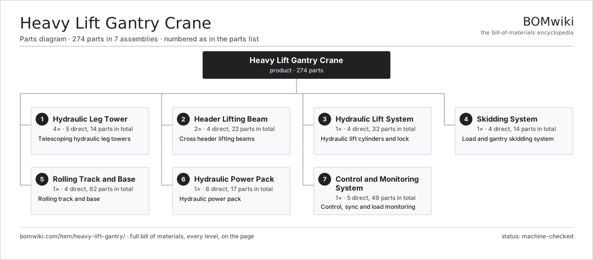
| # | Part | Qty | What it does |
|---|---|---|---|
| 1 | Hydraulic Leg Tower 5 parts | 4× | Telescoping hydraulic leg towers |
| 2 | Header Lifting Beam 4 parts | 2× | Cross header lifting beams |
| 3 | Hydraulic Lift System 4 parts | 1× | Hydraulic lift cylinders and lock |
| 4 | Skidding System 4 parts | 1× | Load and gantry skidding system |
| 5 | Rolling Track and Base 4 parts | 1× | Rolling track and base |
| 6 | Hydraulic Power Pack 6 parts | 1× | Hydraulic power pack |
| 7 | Control and Monitoring System 5 parts | 1× | Control, sync and load monitoring |
3D model
No 3D model yet. Have a CAD file of this? Add a 3D model — STL renders right on this page; STEP, FreeCAD, and OpenSCAD sources are welcome too (openly licensed, like all 3D models on BOMwiki).
Build & assembly graph
expand / collapse · shared sub-assemblies converge · links to related products · est. labourTap an assembly to expand/collapse · tap a part to open it · use “Open page” for any node · drag to pan, scroll to zoom.
Bill of materials for Heavy Lift Gantry Crane
7 top-level lines · 70 rows shown · 274 parts total · indented to 3 levels| # | Item / sub-assembly | Part no. | Qty/assy | Ext. qty | Parts | Type |
|---|---|---|---|---|---|---|
| 1 | Hydraulic Leg Tower 5 parts | heavy-lift-gantry-leg-tower | 4× | 4 | 14 | assembly |
| 1.1 | Base Column Section | heavy-lift-gantry-base-section | 1× | 4 | · | part |
| 1.2 | Telescoping Section | heavy-lift-gantry-telescope-section | 3× | 12 | · | part |
| 1.3 | Stage Locking Pin | heavy-lift-gantry-stage-pin | 8× | 32 | · | part |
| 1.4 | Foot Pad | heavy-lift-gantry-leg-pad | 1× | 4 | · | part |
| 1.5 | Leg Tilt Sensor | heavy-lift-gantry-tilt-sensor | 1× | 4 | · | part |
| 2 | Header Lifting Beam 4 parts | heavy-lift-gantry-header-beam | 2× | 2 | 22 | assembly |
| 2.1 | Header Box Girder | heavy-lift-gantry-header-girder | 1× | 2 | · | part |
| 2.2 | Load Trolley 5 parts | heavy-lift-gantry-load-trolley | 1× | 2 | 15 | assembly |
| 2.2.1 | Trolley Wheel | heavy-lift-gantry-trolley-wheel | 4× | 8 | · | part |
| 2.2.2 | Ball Bearing | ball-bearing | 8× | 16 | · | part |
| 2.2.3 | Trolley Travel Drive | heavy-lift-gantry-trolley-drive | 1× | 2 | · | part |
| 2.2.4 | Gearbox Housing | gearbox-housing | 1× | 2 | · | part |
| 2.2.5 | Helical Gear Pair | gear-pair | 1× | 2 | · | part |
| 2.3 | Load Attachment Link | heavy-lift-gantry-lift-link | 4× | 8 | · | part |
| 2.4 | Header Saddle | heavy-lift-gantry-header-saddle | 2× | 4 | · | part |
| 3 | Hydraulic Lift System 4 parts | heavy-lift-gantry-lift-system | 1× | 1 | 32 | assembly |
| 3.1 | Main Lift Cylinder 4 parts | heavy-lift-gantry-lift-cylinder | 4× | 4 | 5 | assembly |
| 3.1.1 | Cylinder Tube and Rod | heavy-lift-gantry-cyl-tube | 1× | 4 | · | part |
| 3.1.2 | Piston and Seal Carrier | heavy-lift-gantry-cyl-piston | 1× | 4 | · | part |
| 3.1.3 | O-Ring Set | oring-set | 1× | 4 | · | part |
| 3.1.4 | Oil Seal | oil-seal | 2× | 8 | · | part |
| 3.2 | Mechanical Lock Collar | heavy-lift-gantry-lock-collar | 4× | 4 | · | part |
| 3.3 | Counterbalance Lock Valve | heavy-lift-gantry-cyl-valve | 4× | 4 | · | part |
| 3.4 | Pressure Sensor | pressure-sensor | 4× | 4 | · | part |
| 4 | Skidding System 4 parts | heavy-lift-gantry-skid-system | 1× | 1 | 14 | assembly |
| 4.1 | PTFE Skid Shoe | heavy-lift-gantry-skid-shoe | 4× | 4 | · | part |
| 4.2 | Skid Push-Pull Cylinder 3 parts | heavy-lift-gantry-skid-cylinder | 2× | 2 | 3 | assembly |
| 4.2.1 | Skid Cylinder Body | heavy-lift-gantry-skid-cyl-body | 1× | 2 | · | part |
| 4.2.2 | O-Ring Set | oring-set | 1× | 2 | · | part |
| 4.2.3 | Pressure Sensor | pressure-sensor | 1× | 2 | · | part |
| 4.3 | Skid Track Gripper | heavy-lift-gantry-skid-gripper | 2× | 2 | · | part |
| 4.4 | Skid Track Beam | heavy-lift-gantry-skid-beam | 2× | 2 | · | part |
| 5 | Rolling Track and Base 4 parts | heavy-lift-gantry-track-system | 1× | 1 | 62 | assembly |
| 5.1 | Track Rail | heavy-lift-gantry-rail | 4× | 4 | · | part |
| 5.2 | Travel Bogie 3 parts | heavy-lift-gantry-bogie | 4× | 4 | 13 | assembly |
| 5.2.1 | Bogie Wheel | heavy-lift-gantry-bogie-wheel | 4× | 16 | · | part |
| 5.2.2 | Ball Bearing | ball-bearing | 8× | 32 | · | part |
| 5.2.3 | Equalising Bogie Frame | heavy-lift-gantry-bogie-frame | 1× | 4 | · | part |
| 5.3 | Base Distribution Beam | heavy-lift-gantry-base-beam | 2× | 2 | · | part |
| 5.4 | Rail Clamp | heavy-lift-gantry-rail-clamp | 4× | 4 | · | part |
| 6 | Hydraulic Power Pack 6 parts | heavy-lift-gantry-power-pack | 1× | 1 | 17 | assembly |
| 6.1 | Hydraulic Pump | heavy-lift-gantry-pump | 2× | 2 | · | part |
| 6.2 | Prime Mover 2 parts | heavy-lift-gantry-prime-mover | 1× | 1 | 2 | assembly |
| 6.2.1 | Electric Drive Motor | heavy-lift-gantry-motor | 1× | 1 | · | part |
| 6.2.2 | Pump Drive Coupling | heavy-lift-gantry-coupling | 1× | 1 | · | part |
| 6.3 | Reservoir and Cooling 2 parts | heavy-lift-gantry-tank | 1× | 1 | 3 | assembly |
| 6.3.1 | Air-Blast Oil Cooler | heavy-lift-gantry-oil-cooler | 1× | 1 | · | part |
| 6.3.2 | Hydraulic Filter | heavy-lift-gantry-filter | 2× | 2 | · | part |
| 6.4 | Synchronisation Manifold 3 parts | heavy-lift-gantry-sync-manifold | 1× | 1 | 7 | assembly |
| 6.4.1 | Proportional Valve | heavy-lift-gantry-prop-valve | 4× | 4 | · | part |
| 6.4.2 | System Relief Valve | heavy-lift-gantry-relief-valve | 2× | 2 | · | part |
| 6.4.3 | O-Ring Set | oring-set | 1× | 1 | · | part |
| 6.5 | High Pressure Hose Set | heavy-lift-gantry-hose-set | 1× | 1 | · | part |
| 6.6 | O-Ring Set | oring-set | 2× | 2 | · | part |
| 7 | Control and Monitoring System 5 parts | heavy-lift-gantry-control-system | 1× | 1 | 49 | assembly |
| 7.1 | PLC Control Cabinet 7 parts | heavy-lift-gantry-plc-cabinet | 1× | 1 | 38 | assembly |
| 7.1.1 | Bare PCB | pcb-bare | 4× | 4 | · | part |
| 7.1.2 | Microcontroller | mcu | 2× | 2 | · | part |
| 7.1.3 | SMD Passive (R/C/L) | smd-passives | 1× | 1 | · | part |
| 7.1.4 | Relay | relay | 10× | 10 | · | part |
| 7.1.5 | Connector | connector | 18× | 18 | · | part |
| 7.1.6 | Power Supply | power-supply | 2× | 2 | · | part |
| 7.1.7 | LCD Panel | lcd-panel | 1× | 1 | · | part |
| 7.2 | Radio Remote Control 2 parts | heavy-lift-gantry-remote | 1× | 1 | 2 | assembly |
| 7.2.1 | Radio Transmitter | heavy-lift-gantry-radio-tx | 1× | 1 | · | part |
| 7.2.2 | LCD Panel | lcd-panel | 1× | 1 | · | part |
| 7.3 | Load Cell | heavy-lift-gantry-load-cell | 4× | 4 | · | part |
| 7.4 | Cylinder Stroke Sensor | heavy-lift-gantry-stroke-sensor | 4× | 4 | · | part |
| 7.5 | Wire Bundle | wire-bundle | 1× | 1 | · | part |
Related products
same domain, ranked by shared parts Articulated Forklift
2,417 parts · shares 5 with this page
Coal Yard Stacker
571 parts · shares 5 with this page
Dense-Phase Conveying System
446 parts · shares 5 with this page
Order Picker
708 parts · shares 5 with this page
Articulated Forklift
2,417 parts · shares 5 with this page
Coal Yard Stacker
571 parts · shares 5 with this page
Dense-Phase Conveying System
446 parts · shares 5 with this page
Order Picker
708 parts · shares 5 with this page
 Reach Truck
832 parts · shares 5 with this page
Reach Truck
832 parts · shares 5 with this page
 Straddle Lift Crane
672 parts · shares 5 with this page
Straddle Lift Crane
672 parts · shares 5 with this page
Sourcing: possible vendors
Prices, MOQ, and lead times are algorithmic estimates, not quotes, and not claims about these companies. Company mappings are curated by keyword; est. price band $2k–$300k. How estimates work| Vendor | HQ | Specialty | MOQ | Lead time |
|---|---|---|---|---|
| toyota-industries.com ↗ | Kariya, JP | Forklifts & logistics | 20 units | 10–16 wks |
| kiongroup.com ↗ | Frankfurt, DE | Forklifts (Linde, STILL) | 20 units | 10–16 wks |
| jungheinrich.com ↗ | Hamburg, DE | Warehouse trucks | 20 units | 10–16 wks |
| crown.com ↗ | New Bremen, US | Forklifts | 20 units | 10–16 wks |
|
🇨🇳Hangcha
hcforklift.com ↗
|
Hangzhou, CN | Forklifts & material handling | 20 units | 10–16 wks |
1,029-word article