Monorail Hoist System
ProductOverview
A monorail hoist system moves loads along a fixed overhead path defined by a single runway beam. Unlike a bridge crane, which spans two parallel rails and covers a rectangular area, the monorail follows one line of travel that can run straight, curve, branch through switches, or climb gradients. This makes it the natural choice for production lines, paint shops, foundries, and warehouse aisles where material follows a defined route rather than needing coverage of a whole bay. Capacities in common use run from 500 kg up to about 12.5 tonnes.
The system has three working motions. The Wire Rope Lifting Unit raises and lowers the load on a wire rope. The Travel Trolley carries that hoist along the Monorail Track. The load itself hangs from the Hook Block. Power reaches the moving trolley through a Festoon Power Feed cable system, and the operator works the machine from a Pendant Controller hung at working height.
The runway and travel
The Monorail Track is the backbone of the installation. A standard build uses a hot-rolled I-beam, often an IPE or HEB section in S355JR steel, with the lower flange acting as the running surface for the trolley wheels. Long runs are made from several Runway Beam sections joined by bolted Track Joint Plate fishplates that keep the flange edges aligned within a millimetre so the trolley does not snag at the seam. The whole beam hangs from the building roof structure on regularly spaced Suspension Clamp units, typically every 1.5 to 3 metres depending on load and beam stiffness. Where the route must bend, a Curved Track Segment of pre-formed beam routes the path around columns or process equipment, with a minimum radius set by the trolley wheelbase.
The Travel Trolley grips the beam from below. Four flanged Trolley Wheel units, two driven and two idling, run on the flange edges, each turning on a pair of sealed Ball Bearing units. The driven pair is turned by a Travel Drive Motor, a geared brake motor whose Travel Brake holds the trolley in place when stopped. The motor feeds a Travel Reduction Gearbox that steps speed down to the travel rate. A Travel Buffer on each end of the trolley frame absorbs the impact if the carriage runs into the End Stop at the limit of travel.
How the load is lifted
Inside the Wire Rope Lifting Unit, a two-speed Lift Motor drives a Lift Gearbox that turns the Rope Drum. The drum is a grooved steel cylinder that spools the Lifting Wire Rope in a single helical layer, which keeps the rope from crushing itself and gives a predictable rope position for the limit switches. A spring-loaded Rope Guide presses against the drum and lays each turn of rope neatly into its groove as the drum rotates, preventing the rope from jumping a pitch under slack-line conditions.
When the operator releases the lift button, the Lift Brake sets. This is a spring-applied, electrically released disc brake sized to roughly 1.6 times the motor torque, so a power failure stops and holds the load rather than letting it run down. The rope passes down to the Hook Block, where it reeves around grooved Rope Sheave wheels and back up to an anchor, giving a mechanical advantage that halves the rope tension and the hook speed. The forged Load Hook swivels on a thrust bearing so a twisted sling cannot wind up the rope, and a Hook Safety Latch closes the throat.
Protection and load sensing
A Overload Limiter sits in the rope anchor or the suspension pin. It uses a Pressure Sensor to read rope tension and inhibits further lifting once the load exceeds the rated value, protecting both the rope and the runway structure. At the top and bottom of the lift range, geared Hoist Limit Switch units cut the control circuit before the hook block reaches the drum or the floor. The whole system is isolated for maintenance by a lockable Mains Isolator.
Power feed and control
Because the trolley moves, its power cannot be hard-wired. The Festoon Power Feed system solves this with a string of Cable Trolley carriers riding in a Festoon C-Rail beside the runway. They carry loops of Flat Festoon Cable that fold and stretch as the trolley moves, dragged along by a Tow Arm. The Control Panel panel holds a Variable Frequency Drive for smooth travel acceleration, reversing Reversing Contactor units for the lift motor, and a Control Transformer that supplies 48 V to the Push-Button Station. The pendant cable carries an internal strain wire so the conductors bear no mechanical load, and a Emergency Stop Button cuts all motion immediately.
Variants and use
Inverter-fed lift drives replace the two-speed motor where positioning accuracy matters, giving stepless speed and gentle load handling. Powered switches and turntables let one runway feed several branch lines, so a single hoist can serve multiple workstations. Explosion-proof builds for paint lines use sealed motors and spark-free wheels. Low-headroom versions integrate the hoist into the trolley frame to claw back lift height under a low roof. In foundries and forging shops the rope and hook are upgraded for heat exposure, while clean-process lines use stainless rope and washdown-rated enclosures.
Monorail Hoist System parts and their functions
9 top-level parts · 170 parts in total · full bill of materials below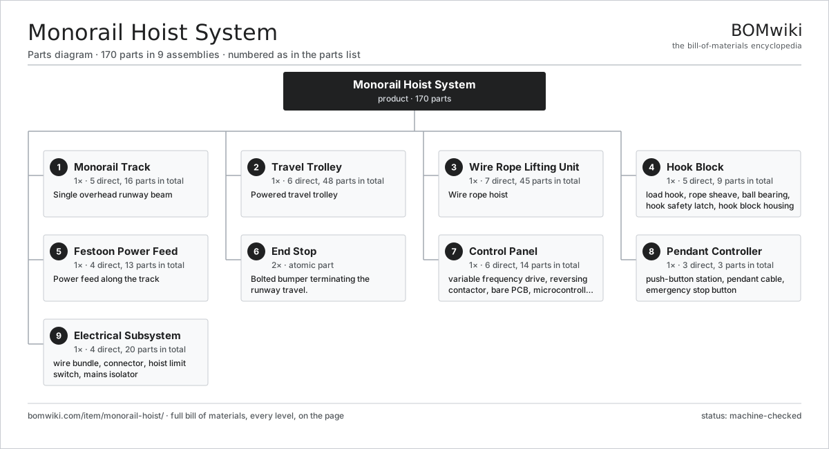
| # | Part | Qty | What it does |
|---|---|---|---|
| 1 | Monorail Track 5 parts | 1× | Single overhead runway beam |
| 2 | Travel Trolley 6 parts | 1× | Powered travel trolley |
| 3 | Wire Rope Lifting Unit 7 parts | 1× | Wire rope hoist |
| 4 | Hook Block 5 parts | 1× | Reeved sheave block carrying the load hook. |
| 5 | Festoon Power Feed 4 parts | 1× | Power feed along the track |
| 6 | End Stop | 2× | Bolted bumper terminating the runway travel. |
| 7 | Control Panel 6 parts | 1× | Contactor and inverter control for lift and travel motors. |
| 8 | Pendant Controller 3 parts | 1× | Hand-held push-button station hung from the trolley. |
| 9 | Electrical Subsystem 4 parts | 1× |
3D model
No 3D model yet. Have a CAD file of this? Add a 3D model — STL renders right on this page; STEP, FreeCAD, and OpenSCAD sources are welcome too (openly licensed, like all 3D models on BOMwiki).
Build & assembly graph
expand / collapse · shared sub-assemblies converge · links to related products · est. labourTap an assembly to expand/collapse · tap a part to open it · use “Open page” for any node · drag to pan, scroll to zoom.
Bill of materials for Monorail Hoist System
9 top-level lines · 68 rows shown · 170 parts total · indented to 3 levels| # | Item / sub-assembly | Part no. | Qty/assy | Ext. qty | Parts | Type |
|---|---|---|---|---|---|---|
| 1 | Monorail Track 5 parts | monorail-hoist-track | 1× | 1 | 16 | assembly |
| 1.1 | Runway Beam | monorail-hoist-runway-beam | 1× | 1 | · | part |
| 1.2 | Track Joint Plate | monorail-hoist-track-joint | 4× | 4 | · | part |
| 1.3 | Suspension Clamp | monorail-hoist-suspension-clamp | 8× | 8 | · | part |
| 1.4 | Curved Track Segment | monorail-hoist-curve-segment | 2× | 2 | · | part |
| 1.5 | Fastener Set | fastener-set | 1× | 1 | · | part |
| 2 | Travel Trolley 6 parts | monorail-hoist-trolley | 1× | 1 | 48 | assembly |
| 2.1 | Trolley Frame | monorail-hoist-trolley-frame | 1× | 1 | · | part |
| 2.2 | Trolley Wheel | monorail-hoist-trolley-wheel | 4× | 4 | · | part |
| 2.3 | Ball Bearing | ball-bearing | 8× | 8 | · | part |
| 2.4 | Travel Drive Motor 4 parts | monorail-hoist-travel-motor | 1× | 1 | 24 | assembly |
| 2.4.1 | Stator Assembly 3 parts + deeper › | stator-assembly | 1× | 1 | 3 | assembly |
| 2.4.2 | Rotor Assembly 4 parts + deeper › | rotor-assembly | 1× | 1 | 19 | assembly |
| 2.4.3 | Motor Housing | motor-housing | 1× | 1 | · | part |
| 2.4.4 | Travel Brake | monorail-hoist-travel-brake | 1× | 1 | · | part |
| 2.5 | Travel Reduction Gearbox 4 parts | monorail-hoist-trolley-gearbox | 1× | 1 | 9 | assembly |
| 2.5.1 | Helical Gear Pair | gear-pair | 2× | 2 | · | part |
| 2.5.2 | Gearbox Housing | gearbox-housing | 1× | 1 | · | part |
| 2.5.3 | Ball Bearing | ball-bearing | 4× | 4 | · | part |
| 2.5.4 | Oil Seal | oil-seal | 2× | 2 | · | part |
| 2.6 | Travel Buffer | monorail-hoist-buffer | 2× | 2 | · | part |
| 3 | Wire Rope Lifting Unit 7 parts | monorail-hoist-lifting-unit | 1× | 1 | 45 | assembly |
| 3.1 | Rope Drum | monorail-hoist-rope-drum | 1× | 1 | · | part |
| 3.2 | Lifting Wire Rope | monorail-hoist-wire-rope | 1× | 1 | · | part |
| 3.3 | Lift Motor 4 parts | monorail-hoist-lift-motor | 1× | 1 | 25 | assembly |
| 3.3.1 | Stator Assembly 3 parts + deeper › | stator-assembly | 1× | 1 | 3 | assembly |
| 3.3.2 | Rotor Assembly 4 parts + deeper › | rotor-assembly | 1× | 1 | 19 | assembly |
| 3.3.3 | Motor Housing | motor-housing | 1× | 1 | · | part |
| 3.3.4 | Ball Bearing | ball-bearing | 2× | 2 | · | part |
| 3.4 | Lift Gearbox 4 parts | monorail-hoist-lift-gearbox | 1× | 1 | 12 | assembly |
| 3.4.1 | Helical Gear Pair | gear-pair | 3× | 3 | · | part |
| 3.4.2 | Gearbox Housing | gearbox-housing | 1× | 1 | · | part |
| 3.4.3 | Ball Bearing | ball-bearing | 6× | 6 | · | part |
| 3.4.4 | Oil Seal | oil-seal | 2× | 2 | · | part |
| 3.5 | Lift Brake | monorail-hoist-lift-brake | 1× | 1 | · | part |
| 3.6 | Rope Guide | monorail-hoist-rope-guide | 1× | 1 | · | part |
| 3.7 | Overload Limiter 3 parts | monorail-hoist-load-limiter | 1× | 1 | 4 | assembly |
| 3.7.1 | Pressure Sensor | pressure-sensor | 1× | 1 | · | part |
| 3.7.2 | Bare PCB | pcb-bare | 1× | 1 | · | part |
| 3.7.3 | Relay | relay | 2× | 2 | · | part |
| 4 | Hook Block 5 parts | monorail-hoist-hook-block | 1× | 1 | 9 | assembly |
| 4.1 | Load Hook | monorail-hoist-hook | 1× | 1 | · | part |
| 4.2 | Rope Sheave | monorail-hoist-sheave | 2× | 2 | · | part |
| 4.3 | Ball Bearing | ball-bearing | 4× | 4 | · | part |
| 4.4 | Hook Safety Latch | monorail-hoist-safety-latch | 1× | 1 | · | part |
| 4.5 | Hook Block Housing | monorail-hoist-block-housing | 1× | 1 | · | part |
| 5 | Festoon Power Feed 4 parts | monorail-hoist-festoon | 1× | 1 | 13 | assembly |
| 5.1 | Cable Trolley | monorail-hoist-festoon-trolley | 10× | 10 | · | part |
| 5.2 | Festoon C-Rail | monorail-hoist-c-rail | 1× | 1 | · | part |
| 5.3 | Flat Festoon Cable | monorail-hoist-flat-cable | 1× | 1 | · | part |
| 5.4 | Tow Arm | monorail-hoist-tow-arm | 1× | 1 | · | part |
| 6 | End Stop | monorail-hoist-end-stops | 2× | 2 | · | part |
| 7 | Control Panel 6 parts | monorail-hoist-control | 1× | 1 | 14 | assembly |
| 7.1 | Variable Frequency Drive | monorail-hoist-vfd | 1× | 1 | · | part |
| 7.2 | Reversing Contactor | monorail-hoist-contactor | 4× | 4 | · | part |
| 7.3 | Bare PCB | pcb-bare | 1× | 1 | · | part |
| 7.4 | Microcontroller | mcu | 1× | 1 | · | part |
| 7.5 | Relay | relay | 6× | 6 | · | part |
| 7.6 | Control Transformer | monorail-hoist-transformer | 1× | 1 | · | part |
| 8 | Pendant Controller 3 parts | monorail-hoist-pendant | 1× | 1 | 3 | assembly |
| 8.1 | Push-Button Station | monorail-hoist-pendant-station | 1× | 1 | · | part |
| 8.2 | Pendant Cable | monorail-hoist-pendant-cable | 1× | 1 | · | part |
| 8.3 | Emergency Stop Button | monorail-hoist-estop | 1× | 1 | · | part |
| 9 | Electrical Subsystem 4 parts | monorail-hoist-electrical | 1× | 1 | 20 | assembly |
| 9.1 | Wire Bundle | wire-bundle | 1× | 1 | · | part |
| 9.2 | Connector | connector | 16× | 16 | · | part |
| 9.3 | Hoist Limit Switch | monorail-hoist-limit-switch | 2× | 2 | · | part |
| 9.4 | Mains Isolator | monorail-hoist-isolator | 1× | 1 | · | part |
Related products
same domain, ranked by shared parts Articulated Forklift
2,417 parts · shares 2 with this page
Articulated Forklift
2,417 parts · shares 2 with this page
 Bag Dump Station
134 parts · shares 2 with this page
Bag Dump Station
134 parts · shares 2 with this page
 Container Handler
552 parts · shares 2 with this page
Container Handler
552 parts · shares 2 with this page
 Dilute-Phase Conveying System
509 parts · shares 2 with this page
Dilute-Phase Conveying System
509 parts · shares 2 with this page
 Forklift
4,153 parts · shares 2 with this page
Forklift
4,153 parts · shares 2 with this page
 Layer Palletizer
857 parts · shares 2 with this page
Layer Palletizer
857 parts · shares 2 with this page
Sourcing: possible vendors
Prices, MOQ, and lead times are algorithmic estimates, not quotes, and not claims about these companies. Company mappings are curated by keyword; est. price band $2k–$300k. How estimates work| Vendor | HQ | Specialty | MOQ | Lead time |
|---|---|---|---|---|
| toyota-industries.com ↗ | Kariya, JP | Forklifts & logistics | 20 units | 10–16 wks |
| kiongroup.com ↗ | Frankfurt, DE | Forklifts (Linde, STILL) | 20 units | 10–16 wks |
| jungheinrich.com ↗ | Hamburg, DE | Warehouse trucks | 20 units | 10–16 wks |
| crown.com ↗ | New Bremen, US | Forklifts | 20 units | 10–16 wks |
|
🇨🇳Hangcha
hcforklift.com ↗
|
Hangzhou, CN | Forklifts & material handling | 20 units | 10–16 wks |
941-word article