Straddle Lift Crane
ProductOverview
A straddle lift crane is a self-propelled gantry on rubber tires that drives over a load, lifts it clear of the ground with four synchronized hoists, and carries it across an open yard. Unlike a rail-mounted gantry, it needs no fixed track: the four steered wheel bogies let it travel in any direction over a prepared surface, position itself around a precast beam, a boat hull, or a power transformer, and move that load to a storage bay or transport trailer. The whole machine is a portal, an inverted U of steel that straddles the load so the lifting points sit directly above it.
The design solves a specific yard problem. Precast concrete plants and boatyards produce items too heavy for a forklift and too awkward for a mobile crane to reach without long reach radii. A straddle gantry sits over the item, picks it up with vertical lift lines, and walks it away. Because the load hangs inside the leg footprint rather than out on a boom, the machine stays stable without counterweight or outriggers.
Portal Frame
The Portal Frame is the load-bearing skeleton. Two Top Box Girder box girders run the length of the machine and carry the four Hoist Unit winches at their ends. Two Cross Tie Beam members tie the left and right sides together so the frame resists the twisting that an off-center load would impose. Four Portal Leg columns drop from the top beams to the running gear, and a Corner Casting forms each knee joint, spreading the bending moment from a leg into the beam rather than concentrating it at a sharp weld. Steel grade is typically S355 for the box sections, with thicker plate at the corner regions. A Maintenance Walkway runs along each top beam so crews can reach the hoists and reeving for inspection.
Running Gear and Steering
Each corner carries a Wheel Bogie. The bogie holds a pair of Industrial Tire wheels driven by a Hydraulic Wheel Motor, a radial-piston hydraulic motor with an integral hub reduction that delivers high torque at the slow speeds a laden gantry needs. The entire bogie rotates on a Slewing Ring Bearing, a large four-point-contact slewing ring, driven by a Steering Cylinder. Because all four bogies can rotate independently, the machine has three steering modes. In crab mode every wheel points the same way and the gantry tracks sideways while staying square to the load. In coordinated mode the wheels follow an Ackermann-style geometry for normal turning. In carousel mode the wheels align tangent to a circle so the whole machine pivots about its own center, which is how an operator spins a long beam in a tight bay. A Steering Encoder on each ring reports the true bogie angle so the PLC can hold the geometry exactly.
Hoist System
Lifting is done by four Hoist Unit winches, one at each top-beam end. Each unit uses a Hoist Drive Motor driving a reduction through a Helical Gear Pair set inside a Gearbox Housing, turning a grooved Rope Drum. The Hoist Wire Rope reeves through a Sheave Block to multiply the falls and reduce line pull, then drops to the spreader corner. A spring-applied Hoist Holding Brake locks the drum whenever hoist pressure is released, so the load holds on power loss. The four winches run under synchronized control: the PLC trims each winch speed so all four corners rise at the same rate and the load stays level even if its center of gravity is off-center. Drum and shaft loads run on Ball Bearing pairs, and Oil Seal elements keep gear oil in the housings.
Power and Hydraulics
A Diesel Power Pack supplies the machine. A constant-speed Diesel Engine of 200-400 kW drives two Main Hydraulic Pump variable-displacement pumps and a belt-driven Control Generator for control and lighting power. A Cooling Pack handles engine, charge-air, and oil heat, and a Fuel Tank feeds the engine through a water-separating filter. Pump flow goes to the Hydraulic System, where a Control Valve Block manifold of proportional spool valves meters oil to the drive, steer, hoist, and brake circuits. A Hydraulic Reservoir holds the oil with return filtration, Hydraulic Accumulator units stabilize pilot and brake pressure, and a Pressure Sensor in each circuit lets the controller watch for overload or a stuck actuator. The Hose & Tube Set routes high-pressure lines down the legs to the corners, with O-Ring Set seals at the fittings.
Operator Cabin and Controls
The Operator Cabin sits high on one corner for a clear view of the load and the wheels. Inside, the operator works from a Operator Seat with two Control Joystick controls, one for travel and steering, one for the hoists, plus LCD Panel displays showing load per corner, steering geometry, and rear cameras. A Cabin HVAC Unit keeps the cabin usable through long shifts in heat or cold. The Control System behind it is built around a safety-rated Machine PLC and four Corner I/O Module corner nodes that read the Hoist Load Pin pins and the steering encoders and drive the corner valves. A Power Supply feeds the 24 V logic, and a Wire Bundle with field Connector sets links the corners back to the cabin. The controller refuses to lift if total or per-corner load exceeds the rated chart, and it blends the four hoists so the load never racks.
Lifting Attachment
The load hangs from a Lifting Spreader. A telescoping Spreader Beam adjusts the lift-point spacing to match the item width, and four Lifting Sling legs run down to the load through Hook Block hooks with self-closing latches. Lifting Shackle connectors join the slings to the spreader and to the load's cast-in lifting anchors. For long precast beams the spreader spans most of the length so the beam is lifted at its design pick points and not stressed in bending.
Use and Operation
In a precast yard the gantry drives empty over a freshly cured beam, the crew rigs the spreader to the beam anchors, and the operator lifts all four corners together until the beam clears its casting bed. The machine then crabs sideways out of the casting line and travels to the storage area, where it sets the beam on dunnage and releases the slings. In a boatyard the same machine, often called a boat hoist, lifts hulls from the water on soft slings and carries them to hardstand. Travel is slow and deliberate, ground preparation matters because the wheel loads are high, and the operator watches per-corner load continuously since an unevenly rigged load shifts weight toward one leg.
Straddle Lift Crane parts and their functions
8 top-level parts · 672 parts in total · full bill of materials below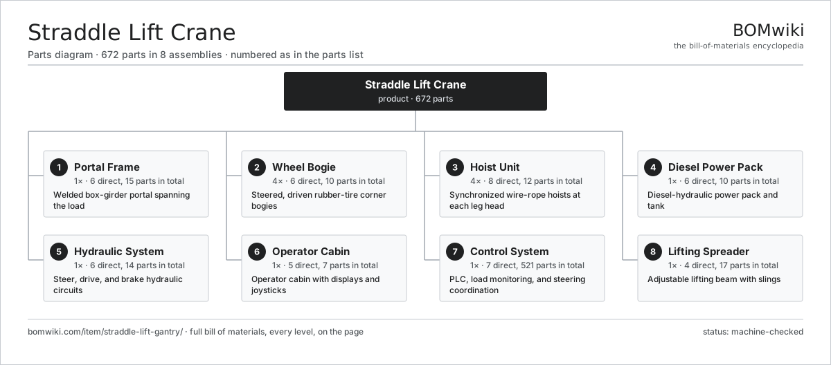
| # | Part | Qty | What it does |
|---|---|---|---|
| 1 | Portal Frame 6 parts | 1× | Welded box-girder portal spanning the load |
| 2 | Wheel Bogie 6 parts | 4× | Steered, driven rubber-tire corner bogies |
| 3 | Hoist Unit 8 parts | 4× | Synchronized wire-rope hoists at each leg head |
| 4 | Diesel Power Pack 6 parts | 1× | Diesel-hydraulic power pack and tank |
| 5 | Hydraulic System 6 parts | 1× | Steer, drive, and brake hydraulic circuits |
| 6 | Operator Cabin 5 parts | 1× | Operator cabin with displays and joysticks |
| 7 | Control System 7 parts | 1× | PLC, load monitoring, and steering coordination |
| 8 | Lifting Spreader 4 parts | 1× | Adjustable lifting beam with slings |
3D model
No 3D model yet. Have a CAD file of this? Add a 3D model — STL renders right on this page; STEP, FreeCAD, and OpenSCAD sources are welcome too (openly licensed, like all 3D models on BOMwiki).
Build & assembly graph
expand / collapse · shared sub-assemblies converge · links to related products · est. labourTap an assembly to expand/collapse · tap a part to open it · use “Open page” for any node · drag to pan, scroll to zoom.
Bill of materials for Straddle Lift Crane
8 top-level lines · 63 rows shown · 672 parts total · indented to 3 levels| # | Item / sub-assembly | Part no. | Qty/assy | Ext. qty | Parts | Type |
|---|---|---|---|---|---|---|
| 1 | Portal Frame 6 parts | straddle-lift-gantry-portal-frame | 1× | 1 | 15 | assembly |
| 1.1 | Top Box Girder | straddle-lift-gantry-top-beam | 2× | 2 | · | part |
| 1.2 | Cross Tie Beam | straddle-lift-gantry-cross-beam | 2× | 2 | · | part |
| 1.3 | Portal Leg | straddle-lift-gantry-leg | 4× | 4 | · | part |
| 1.4 | Corner Casting | straddle-lift-gantry-corner-casting | 4× | 4 | · | part |
| 1.5 | Maintenance Walkway | straddle-lift-gantry-walkway | 2× | 2 | · | part |
| 1.6 | Fastener Set | fastener-set | 1× | 1 | · | part |
| 2 | Wheel Bogie 6 parts | straddle-lift-gantry-wheel-bogie | 4× | 4 | 10 | assembly |
| 2.1 | Industrial Tire | straddle-lift-gantry-tire | 2× | 8 | · | part |
| 2.2 | Hydraulic Wheel Motor | straddle-lift-gantry-wheel-motor | 1× | 4 | · | part |
| 2.3 | Steering Cylinder | straddle-lift-gantry-steer-cylinder | 1× | 4 | · | part |
| 2.4 | Slewing Ring Bearing | straddle-lift-gantry-slew-bearing | 1× | 4 | · | part |
| 2.5 | Bogie Frame | straddle-lift-gantry-bogie-frame | 1× | 4 | · | part |
| 2.6 | Ball Bearing | ball-bearing | 4× | 16 | · | part |
| 3 | Hoist Unit 8 parts | straddle-lift-gantry-hoist-unit | 4× | 4 | 12 | assembly |
| 3.1 | Hoist Drive Motor | straddle-lift-gantry-hoist-motor | 1× | 4 | · | part |
| 3.2 | Rope Drum | straddle-lift-gantry-rope-drum | 1× | 4 | · | part |
| 3.3 | Hoist Wire Rope | straddle-lift-gantry-wire-rope | 1× | 4 | · | part |
| 3.4 | Sheave Block | straddle-lift-gantry-sheave-block | 1× | 4 | · | part |
| 3.5 | Hoist Holding Brake | straddle-lift-gantry-hoist-brake | 1× | 4 | · | part |
| 3.6 | Gearbox Housing | gearbox-housing | 1× | 4 | · | part |
| 3.7 | Helical Gear Pair | gear-pair | 2× | 8 | · | part |
| 3.8 | Ball Bearing | ball-bearing | 4× | 16 | · | part |
| 4 | Diesel Power Pack 6 parts | straddle-lift-gantry-power-unit | 1× | 1 | 10 | assembly |
| 4.1 | Diesel Engine | straddle-lift-gantry-diesel-engine | 1× | 1 | · | part |
| 4.2 | Main Hydraulic Pump | straddle-lift-gantry-main-pump | 2× | 2 | · | part |
| 4.3 | Fuel Tank | straddle-lift-gantry-fuel-tank | 1× | 1 | · | part |
| 4.4 | Cooling Pack | straddle-lift-gantry-cooling-pack | 1× | 1 | · | part |
| 4.5 | Control Generator | straddle-lift-gantry-generator | 1× | 1 | · | part |
| 4.6 | Oil Seal | oil-seal | 4× | 4 | · | part |
| 5 | Hydraulic System 6 parts | straddle-lift-gantry-hydraulic-system | 1× | 1 | 14 | assembly |
| 5.1 | Control Valve Block | straddle-lift-gantry-valve-block | 2× | 2 | · | part |
| 5.2 | Hydraulic Reservoir | straddle-lift-gantry-reservoir | 1× | 1 | · | part |
| 5.3 | Hydraulic Accumulator | straddle-lift-gantry-accumulator | 2× | 2 | · | part |
| 5.4 | Hose & Tube Set | straddle-lift-gantry-hose-set | 1× | 1 | · | part |
| 5.5 | Pressure Sensor | pressure-sensor | 6× | 6 | · | part |
| 5.6 | O-Ring Set | oring-set | 2× | 2 | · | part |
| 6 | Operator Cabin 5 parts | straddle-lift-gantry-control-cabin | 1× | 1 | 7 | assembly |
| 6.1 | Cabin Shell | straddle-lift-gantry-cabin-shell | 1× | 1 | · | part |
| 6.2 | Operator Seat | straddle-lift-gantry-operator-seat | 1× | 1 | · | part |
| 6.3 | Control Joystick | straddle-lift-gantry-joystick | 2× | 2 | · | part |
| 6.4 | LCD Panel | lcd-panel | 2× | 2 | · | part |
| 6.5 | Cabin HVAC Unit | straddle-lift-gantry-hvac-unit | 1× | 1 | · | part |
| 7 | Control System 7 parts | straddle-lift-gantry-control-system | 1× | 1 | 521 | assembly |
| 7.1 | Machine PLC 3 parts | straddle-lift-gantry-plc | 1× | 1 | 143 | assembly |
| 7.1.1 | Bare PCB | pcb-bare | 1× | 1 | · | part |
| 7.1.2 | Microcontroller | mcu | 2× | 2 | · | part |
| 7.1.3 | SMD Passive (R/C/L) | smd-passives | 140× | 140 | · | part |
| 7.2 | Corner I/O Module 4 parts | straddle-lift-gantry-io-module | 4× | 4 | 86 | assembly |
| 7.2.1 | Bare PCB | pcb-bare | 1× | 4 | · | part |
| 7.2.2 | Microcontroller | mcu | 1× | 4 | · | part |
| 7.2.3 | Relay | relay | 4× | 16 | · | part |
| 7.2.4 | SMD Passive (R/C/L) | smd-passives | 80× | 320 | · | part |
| 7.3 | Hoist Load Pin | straddle-lift-gantry-load-cell | 4× | 4 | · | part |
| 7.4 | Steering Encoder | straddle-lift-gantry-steer-encoder | 4× | 4 | · | part |
| 7.5 | Power Supply | power-supply | 1× | 1 | · | part |
| 7.6 | Wire Bundle | wire-bundle | 1× | 1 | · | part |
| 7.7 | Connector | connector | 24× | 24 | · | part |
| 8 | Lifting Spreader 4 parts | straddle-lift-gantry-spreader | 1× | 1 | 17 | assembly |
| 8.1 | Spreader Beam | straddle-lift-gantry-spreader-beam | 1× | 1 | · | part |
| 8.2 | Lifting Sling | straddle-lift-gantry-sling | 4× | 4 | · | part |
| 8.3 | Hook Block | straddle-lift-gantry-hook-block | 4× | 4 | · | part |
| 8.4 | Lifting Shackle | straddle-lift-gantry-shackle | 8× | 8 | · | part |
Related products
same domain, ranked by shared parts Articulated Forklift
2,417 parts · shares 5 with this page
Coal Yard Stacker
571 parts · shares 5 with this page
Dense-Phase Conveying System
446 parts · shares 5 with this page
Articulated Forklift
2,417 parts · shares 5 with this page
Coal Yard Stacker
571 parts · shares 5 with this page
Dense-Phase Conveying System
446 parts · shares 5 with this page
 Heavy Lift Gantry Crane
274 parts · shares 5 with this page
Order Picker
708 parts · shares 5 with this page
Heavy Lift Gantry Crane
274 parts · shares 5 with this page
Order Picker
708 parts · shares 5 with this page
 Reach Truck
832 parts · shares 5 with this page
Reach Truck
832 parts · shares 5 with this page
Sourcing: possible vendors
Prices, MOQ, and lead times are algorithmic estimates, not quotes, and not claims about these companies. Company mappings are curated by keyword; est. price band $2k–$300k. How estimates work| Vendor | HQ | Specialty | MOQ | Lead time |
|---|---|---|---|---|
| toyota-industries.com ↗ | Kariya, JP | Forklifts & logistics | 20 units | 10–16 wks |
| kiongroup.com ↗ | Frankfurt, DE | Forklifts (Linde, STILL) | 20 units | 10–16 wks |
| jungheinrich.com ↗ | Hamburg, DE | Warehouse trucks | 20 units | 10–16 wks |
| crown.com ↗ | New Bremen, US | Forklifts | 20 units | 10–16 wks |
|
🇨🇳Hangcha
hcforklift.com ↗
|
Hangzhou, CN | Forklifts & material handling | 20 units | 10–16 wks |
1,224-word article