Telescopic Handler
ProductOverview
A telescopic handler, or telehandler, is the machine that reaches where a forklift cannot. Instead of a vertical mast it carries a single extending boom that pivots up from near the cab and telescopes outward, so it can place a load high on a building or far across an obstacle from a fixed position. That one change makes it the standard lift truck on construction sites, farms, and rental fleets: with a quick-change carriage it swaps from pallet forks to a bucket, a jib crane, or a work platform in minutes. The machine combines a diesel Powertrain, the extending Boom Assembly, a load-sensing Hydraulic System, a long Chassis Frame, a four-wheel-drive Axle System, the Operator Cab, and an Electrical System built around a stability monitor.
Powertrain
The Diesel Engine is a four-cylinder turbo diesel, often near 4.4 L and 75 kW, sized to drive both the wheels and a hungry hydraulic pump at the same time. Behind it the Powershift Transmission is usually a Clutch Pack powershift unit that shifts under load, though hydrostatic drives appear on smaller models for fine inching. A Transfer Case sends torque through two Driveshaft shafts to make the machine four-wheel drive, which it needs because it works on the same broken ground as a rough-terrain forklift but carries a longer, heavier front overhang.
The telescopic boom
The Boom Assembly is what defines the machine. It is a set of nested welded box sections, the Boom Base Section, the Boom Mid Section, and the Boom Fly Section, that slide inside one another. A Boom Lift Cylinder pivots the whole boom up and down about a pin at the rear of the frame, and a Extension Cylinder inside the boom, often working through internal chains or cables, telescopes the sections out. Each section rides on replaceable Wear Pad pads so the steel boxes glide rather than grind. At the tip a Fork Carriage holds the Fork Arm forks, and a Carriage Tilt Cylinder keeps the load level as the boom rises and falls. A Quick Coupler on the carriage is what lets the same machine run forks one hour and a muck bucket the next.
Hydraulics
The boom, carriage, steering, and outriggers all run on the Hydraulic System. A Load-Sensing Pump load-sensing pump supplies only the flow each function asks for, which saves fuel and gives the operator smooth, repeatable motion. The Proportional Valve Bank proportional bank meters that flow: Pilot Solenoid pilots shift the Valve Spool spools in proportion to how far the joystick moves, and a Relief Valve caps pressure near 230 bar. Return oil passes the Hydraulic Filter before going back to the Hydraulic Reservoir, and stiff Hydraulic Hose runs route oil out along the boom.
Chassis, stability, and outriggers
The Main Frame is a long welded box that mounts the boom pivot at the rear and the engine alongside the cab, and a cast Counterweight balances the load held out front. The catch with a telescopic boom is that reaching far forward shifts the load's moment ahead of the front wheels, so stability, not motor power, sets the limit. Larger machines deploy Outrigger stabilizer legs, each with an Outrigger Cylinder and a wide Outrigger Pad, to widen the support base before lifting to full height. The Axle System uses two Drive-Steer Axle axles on Flotation Tire flotation tires, and because both axles steer, the operator can pick front-wheel, four-wheel, or crab steering to crab sideways into a tight bay.
Cab and the load-moment system
From the Operator Cab the operator runs every boom function with one Joystick, steers with the Steering Column, and watches a Display Unit that shows the live load chart. The safety core of the machine is the Load-Moment Controller load-moment indicator in the Electrical System. It reads boom elevation from a Boom Angle Sensor, reach from a Extension Sensor, and the lifted weight, then compares the resulting overturning moment to the rated chart. As the machine approaches its tipping limit the controller warns the operator and then cuts the boom functions that would make it worse, so reaching out too far simply stops rather than tipping the machine.
Variants and use
Compact models lift around 3,000 kg to 6 or 7 m for farm and yard work; large construction models reach 14 m or more and over 4,500 kg, and rotating-turret variants spin the boom 360 degrees to feed several work faces from one setup. The attachment ecosystem is the real product: forks, buckets, sweepers, jib hooks, and personnel platforms all clip to the Quick Coupler, which is why rental fleets carry telehandlers as their general-purpose lift machine.
Telescopic Handler parts and their functions
7 top-level parts · 380 parts in total · full bill of materials below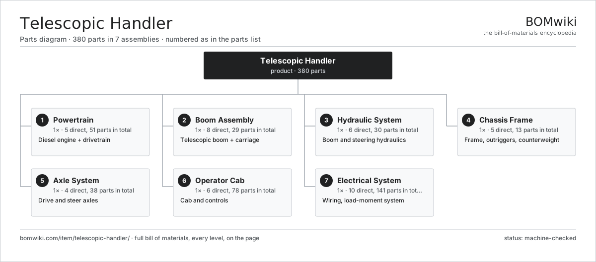
| # | Part | Qty | What it does |
|---|---|---|---|
| 1 | Powertrain 5 parts | 1× | Diesel engine + drivetrain |
| 2 | Boom Assembly 8 parts | 1× | Telescopic boom + carriage |
| 3 | Hydraulic System 6 parts | 1× | Boom and steering hydraulics |
| 4 | Chassis Frame 5 parts | 1× | Frame, outriggers, counterweight |
| 5 | Axle System 4 parts | 1× | Drive and steer axles |
| 6 | Operator Cab 6 parts | 1× | Cab and controls |
| 7 | Electrical System 10 parts | 1× | Wiring, load-moment system |
3D model
No 3D model yet. Have a CAD file of this? Add a 3D model — STL renders right on this page; STEP, FreeCAD, and OpenSCAD sources are welcome too (openly licensed, like all 3D models on BOMwiki).
Build & assembly graph
expand / collapse · shared sub-assemblies converge · links to related products · est. labourTap an assembly to expand/collapse · tap a part to open it · use “Open page” for any node · drag to pan, scroll to zoom.
Bill of materials for Telescopic Handler
7 top-level lines · 97 rows shown · 380 parts total · indented to 3 levels| # | Item / sub-assembly | Part no. | Qty/assy | Ext. qty | Parts | Type |
|---|---|---|---|---|---|---|
| 1 | Powertrain 5 parts | th-powertrain | 1× | 1 | 51 | assembly |
| 1.1 | Diesel Engine 9 parts | th-diesel-engine | 1× | 1 | 31 | assembly |
| 1.1.1 | Cylinder Block | th-engine-block | 1× | 1 | · | part |
| 1.1.2 | Cylinder Head 3 parts + deeper › | th-cylinder-head | 1× | 1 | 17 | assembly |
| 1.1.3 | Piston Assembly | rtf-piston-set | 4× | 4 | · | part |
| 1.1.4 | Crankshaft | rtf-crankshaft | 1× | 1 | · | part |
| 1.1.5 | Turbocharger | rtf-turbocharger | 1× | 1 | · | part |
| 1.1.6 | Injection Pump | rtf-injection-pump | 1× | 1 | · | part |
| 1.1.7 | Engine Radiator | rtf-radiator | 1× | 1 | · | part |
| 1.1.8 | Oil Seal | oil-seal | 4× | 4 | · | part |
| 1.1.9 | Fastener Set | fastener-set | 1× | 1 | · | part |
| 1.2 | Powershift Transmission 5 parts | th-transmission | 1× | 1 | 16 | assembly |
| 1.2.1 | Clutch Pack | rtf-clutch-pack | 3× | 3 | · | part |
| 1.2.2 | Helical Gear Pair | gear-pair | 3× | 3 | · | part |
| 1.2.3 | Gearbox Housing | gearbox-housing | 1× | 1 | · | part |
| 1.2.4 | Ball Bearing | ball-bearing | 6× | 6 | · | part |
| 1.2.5 | Oil Seal | oil-seal | 3× | 3 | · | part |
| 1.3 | Transfer Case | th-transfer-case | 1× | 1 | · | part |
| 1.4 | Driveshaft | rtf-driveshaft | 2× | 2 | · | part |
| 1.5 | Fuel Tank | th-fuel-tank | 1× | 1 | · | part |
| 2 | Boom Assembly 8 parts | th-boom-assembly | 1× | 1 | 29 | assembly |
| 2.1 | Boom Base Section | th-boom-base-section | 1× | 1 | · | part |
| 2.2 | Boom Mid Section | th-boom-mid-section | 1× | 1 | · | part |
| 2.3 | Boom Fly Section | th-boom-fly-section | 1× | 1 | · | part |
| 2.4 | Boom Lift Cylinder 4 parts | th-lift-cylinder | 1× | 1 | 4 | assembly |
| 2.4.1 | Cylinder Barrel | rtf-cylinder-barrel | 1× | 1 | · | part |
| 2.4.2 | Piston Rod | rtf-piston-rod | 1× | 1 | · | part |
| 2.4.3 | O-Ring Set | oring-set | 1× | 1 | · | part |
| 2.4.4 | Rod Seal | rtf-rod-seal | 1× | 1 | · | part |
| 2.5 | Extension Cylinder 3 parts | th-extension-cylinder | 1× | 1 | 3 | assembly |
| 2.5.1 | Cylinder Barrel | rtf-cylinder-barrel | 1× | 1 | · | part |
| 2.5.2 | Piston Rod | rtf-piston-rod | 1× | 1 | · | part |
| 2.5.3 | O-Ring Set | oring-set | 1× | 1 | · | part |
| 2.6 | Wear Pad | th-wear-pad | 12× | 12 | · | part |
| 2.7 | Fork Carriage 4 parts | th-carriage | 1× | 1 | 5 | assembly |
| 2.7.1 | Carriage Plate | rtf-carriage-plate | 1× | 1 | · | part |
| 2.7.2 | Fork Arm | rtf-fork-arm | 2× | 2 | · | part |
| 2.7.3 | Carriage Tilt Cylinder | th-carriage-tilt-cylinder | 1× | 1 | · | part |
| 2.7.4 | Quick Coupler | th-quick-coupler | 1× | 1 | · | part |
| 2.8 | Pivot Pin | th-pivot-pin | 2× | 2 | · | part |
| 3 | Hydraulic System 6 parts | th-hydraulic-system | 1× | 1 | 30 | assembly |
| 3.1 | Load-Sensing Pump | th-hydraulic-pump | 1× | 1 | · | part |
| 3.2 | Proportional Valve Bank 4 parts | th-control-valve | 1× | 1 | 12 | assembly |
| 3.2.1 | Valve Spool | rtf-valve-spool | 5× | 5 | · | part |
| 3.2.2 | Pilot Solenoid | th-solenoid | 5× | 5 | · | part |
| 3.2.3 | Relief Valve | rtf-relief-valve | 1× | 1 | · | part |
| 3.2.4 | O-Ring Set | oring-set | 1× | 1 | · | part |
| 3.3 | Hydraulic Reservoir | th-hydraulic-tank | 1× | 1 | · | part |
| 3.4 | Hydraulic Filter | rtf-hydraulic-filter | 1× | 1 | · | part |
| 3.5 | Hydraulic Hose | rtf-hydraulic-hose | 12× | 12 | · | part |
| 3.6 | Pressure Sensor | pressure-sensor | 3× | 3 | · | part |
| 4 | Chassis Frame 5 parts | th-chassis-frame | 1× | 1 | 13 | assembly |
| 4.1 | Main Frame | th-main-frame | 1× | 1 | · | part |
| 4.2 | Outrigger 3 parts | th-outrigger | 2× | 2 | 3 | assembly |
| 4.2.1 | Outrigger Cylinder | th-outrigger-cylinder | 1× | 2 | · | part |
| 4.2.2 | Outrigger Pad | th-outrigger-pad | 1× | 2 | · | part |
| 4.2.3 | Pivot Pin | rtf-pivot-pin | 1× | 2 | · | part |
| 4.3 | Counterweight | rtf-counterweight | 1× | 1 | · | part |
| 4.4 | Sheet Metal Panel | sheet-panel | 4× | 4 | · | part |
| 4.5 | Fastener Set | fastener-set | 1× | 1 | · | part |
| 5 | Axle System 4 parts | th-axle-system | 1× | 1 | 38 | assembly |
| 5.1 | Drive-Steer Axle 6 parts | th-drive-steer-axle | 2× | 2 | 14 | assembly |
| 5.1.1 | Differential | rtf-differential | 1× | 2 | · | part |
| 5.1.2 | Final Drive | rtf-final-drive | 2× | 4 | · | part |
| 5.1.3 | Steering Knuckle | rtf-steer-knuckle | 2× | 4 | · | part |
| 5.1.4 | Steer Cylinder | rtf-steer-cylinder | 1× | 2 | · | part |
| 5.1.5 | Ball Bearing | ball-bearing | 4× | 8 | · | part |
| 5.1.6 | Oil Seal | oil-seal | 4× | 8 | · | part |
| 5.2 | Flotation Tire | th-tire-flotation | 4× | 4 | · | part |
| 5.3 | Wheel Rim | rtf-wheel-rim | 4× | 4 | · | part |
| 5.4 | Wet Disc Brake | rtf-wet-brake | 2× | 2 | · | part |
| 6 | Operator Cab 6 parts | th-operator-cab | 1× | 1 | 78 | assembly |
| 6.1 | Cab Frame | th-cab-frame | 1× | 1 | · | part |
| 6.2 | Operator Seat | rtf-operator-seat | 1× | 1 | · | part |
| 6.3 | Joystick | th-joystick | 1× | 1 | · | part |
| 6.4 | Steering Column | rtf-steering-column | 1× | 1 | · | part |
| 6.5 | Pedal Set | rtf-pedal-set | 1× | 1 | · | part |
| 6.6 | Display Unit 4 parts | th-display-unit | 1× | 1 | 73 | assembly |
| 6.6.1 | Bare PCB | pcb-bare | 1× | 1 | · | part |
| 6.6.2 | Microcontroller | mcu | 1× | 1 | · | part |
| 6.6.3 | LCD Panel | lcd-panel | 1× | 1 | · | part |
| 6.6.4 | SMD Passive (R/C/L) | smd-passives | 70× | 70 | · | part |
| 7 | Electrical System 10 parts | th-electrical-system | 1× | 1 | 141 | assembly |
| 7.1 | Battery | rtf-battery | 1× | 1 | · | part |
| 7.2 | Alternator | rtf-alternator | 1× | 1 | · | part |
| 7.3 | Starter Motor | rtf-starter-motor | 1× | 1 | · | part |
| 7.4 | Load-Moment Controller 4 parts | th-lmi-controller | 1× | 1 | 93 | assembly |
| 7.4.1 | Bare PCB | pcb-bare | 1× | 1 | · | part |
| 7.4.2 | Microcontroller | mcu | 1× | 1 | · | part |
| 7.4.3 | CAN Transceiver | can-transceiver | 1× | 1 | · | part |
| 7.4.4 | SMD Passive (R/C/L) | smd-passives | 90× | 90 | · | part |
| 7.5 | Boom Angle Sensor | th-boom-angle-sensor | 1× | 1 | · | part |
| 7.6 | Extension Sensor | th-extension-sensor | 1× | 1 | · | part |
| 7.7 | Work Light | rtf-work-light | 4× | 4 | · | part |
| 7.8 | Wire Bundle | wire-bundle | 1× | 1 | · | part |
| 7.9 | Relay | relay | 8× | 8 | · | part |
| 7.10 | Connector | connector | 30× | 30 | · | part |
Related products
same domain, ranked by shared parts Rough-Terrain Forklift
247 parts · shares 37 with this page
Rough-Terrain Forklift
247 parts · shares 37 with this page
 Container Handler
552 parts · shares 31 with this page
Walkie Stacker
541 parts · shares 9 with this page
Order Picker
708 parts · shares 10 with this page
Container Handler
552 parts · shares 31 with this page
Walkie Stacker
541 parts · shares 9 with this page
Order Picker
708 parts · shares 10 with this page
 Empty Container Handler
426 parts · shares 5 with this page
Laden Container Handler
543 parts · shares 5 with this page
Empty Container Handler
426 parts · shares 5 with this page
Laden Container Handler
543 parts · shares 5 with this page
Sourcing: possible vendors
Prices, MOQ, and lead times are algorithmic estimates, not quotes, and not claims about these companies. Company mappings are curated by keyword; est. price band $2k–$300k. How estimates work| Vendor | HQ | Specialty | MOQ | Lead time |
|---|---|---|---|---|
| toyota-industries.com ↗ | Kariya, JP | Forklifts & logistics | 20 units | 10–16 wks |
| kiongroup.com ↗ | Frankfurt, DE | Forklifts (Linde, STILL) | 20 units | 10–16 wks |
| jungheinrich.com ↗ | Hamburg, DE | Warehouse trucks | 20 units | 10–16 wks |
| crown.com ↗ | New Bremen, US | Forklifts | 20 units | 10–16 wks |
|
🇨🇳Hangcha
hcforklift.com ↗
|
Hangzhou, CN | Forklifts & material handling | 20 units | 10–16 wks |
834-word article