Industrial Manipulator Arm
ProductOverview
An industrial manipulator arm lets one operator move heavy or awkward parts as if they weighed almost nothing. The arm carries the full weight of the load through a balancing system, so the operator only has to guide it. Where a hoist lifts straight up and down on a chain or rope, a manipulator holds the load rigidly in space and lets the operator push it in any direction, tilt it, and rotate it, which makes it the tool of choice for assembly lines, machine loading, and packing stations where parts must be positioned precisely and quickly. Payloads run from around 20 kg to 500 kg.
The machine is built from a few cooperating subsystems. The Base Column & Slew anchors it to the floor and lets it slew. The Parallelogram Arm reaches out and keeps the tool level. The Pneumatic Balancer cancels the weight of the load. The Wrist Module and End Effector grip and orient the part. The Pneumatic System and Control System run it, and the Safety System keeps the load from dropping.
The balancing principle
The heart of the machine is the Pneumatic Balancer. A Balance Cylinder applies an upward force to the arm linkage through its Piston Rod, and the Balance Regulator sets the air pressure so this force exactly matches the weight of the arm plus the load. When the two are balanced, the load floats: a light push from the operator moves it, and it stays wherever it is left. A Pressure Sensor reads the cylinder pressure so the system knows how much force it is applying.
Simple balancers need the operator to flip a control between the empty-tool pressure and the loaded pressure. Intelligent balancers go further: the Control System system senses when a part is picked up by the change in load, and a Proportional Valve automatically adjusts the cylinder pressure to keep the arm in balance whether it is loaded or empty. This float mode is what lets an operator move a 200 kg casting with one hand.
Keeping the tool level
The Parallelogram Arm is a parallelogram, a four-bar mechanism made from the Upper Arm, the Forearm, and two Tie Rod links. Because opposite sides of a parallelogram stay parallel as it flexes, the tool mounting at the end of the arm stays at a constant angle no matter how far the arm reaches in or out. This means a part picked up flat stays flat as the operator moves it across the workspace, without any active control. Each joint runs on hardened Pivot Pin pins and Ball Bearing units so the motion stays light and free of slop.
Reach, slew and wrist
The Base Column & Slew is a steel Column Tube on an anchored Base Plate, turning on a large Slew Bearing that gives 360 degrees of rotation, with a Slew Brake to lock a position when needed. Together the parallelogram reach and the column slew give a cylindrical working envelope around the column.
At the end of the arm, the Wrist Module adds orientation. A Wrist Tilt Axis tilts the tool up and down and a Wrist Rotate Axis spins it about its own axis, with a Wrist Brake detenting common angles. The operator works all of this from the Operator Handle, which carries the lift and grip controls under the thumb.
End effectors
The End Effector is the part that touches the load, and it mounts on a Quick-Change Coupling coupling so one arm can serve several jobs. A clamp tool uses a Gripper Cylinder to close a pair of Gripper Jaw jaws around a part, while a vacuum tool uses Vacuum Cup cups for flat or fragile work such as glass and sheet. Custom tooling, like a roll cradle, a drum clamp, or a powered nutrunner spindle, hangs from the same coupling.
Pneumatics, control and safety
The Pneumatic System starts at a Filter-Regulator-Lubricator unit that cleans, regulates, and lubricates the shop air, then routes it through Air Hose lines and Solenoid Valve valves, with a Rotary Air Union carrying air across the slew bearing so the hoses never twist. The Control System system runs on a board with an Microcontroller and a Power Supply, reading handle inputs and metering the balance pressure.
Because the load is held by air pressure, the Safety System is essential. A Drop-Check Valve locks the balance cylinder if air pressure is lost, so the arm holds its position rather than collapsing. A Grip Interlock prevents the operator from releasing a part while it is still gripped and raised, and a Emergency Stop cuts power and locks the arm at once. These measures meet the lifting-accessory requirements of EN 13155.
Variants and use
Manipulators are configured to the job. Floor-column units suit fixed workstations, wall-mounted arms save floor space, and rail or overhead-rail manipulators travel along a line to serve several stations. Tooling defines the application: engine and gearbox assembly, glass and panel handling, drum and roll loading, bag and sack palletising, and machine-tending where the arm loads and unloads a press or lathe. The common thread is removing the lifting effort and the strain injury that comes with it, while keeping the speed and precision of manual handling.
Industrial Manipulator Arm parts and their functions
8 top-level parts · 82 parts in total · full bill of materials below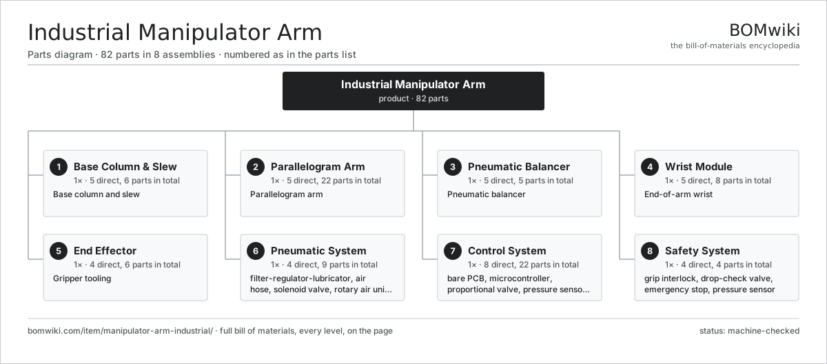
| # | Part | Qty | What it does |
|---|---|---|---|
| 1 | Base Column & Slew 5 parts | 1× | Base column and slew |
| 2 | Parallelogram Arm 5 parts | 1× | Parallelogram arm |
| 3 | Pneumatic Balancer 5 parts | 1× | Pneumatic balancer |
| 4 | Wrist Module 5 parts | 1× | End-of-arm wrist |
| 5 | End Effector 4 parts | 1× | Gripper tooling |
| 6 | Pneumatic System 4 parts | 1× | Air supply, conditioning and routing for balancer and gripper. |
| 7 | Control System 8 parts | 1× | Logic that reads handle inputs and meters balance pressure. |
| 8 | Safety System 4 parts | 1× | Drop prevention and grip interlocks for operator safety. |
3D model
No 3D model yet. Have a CAD file of this? Add a 3D model — STL renders right on this page; STEP, FreeCAD, and OpenSCAD sources are welcome too (openly licensed, like all 3D models on BOMwiki).
Build & assembly graph
expand / collapse · shared sub-assemblies converge · links to related products · est. labourTap an assembly to expand/collapse · tap a part to open it · use “Open page” for any node · drag to pan, scroll to zoom.
Bill of materials for Industrial Manipulator Arm
8 top-level lines · 48 rows shown · 82 parts total · indented to 3 levels| # | Item / sub-assembly | Part no. | Qty/assy | Ext. qty | Parts | Type |
|---|---|---|---|---|---|---|
| 1 | Base Column & Slew 5 parts | manipulator-arm-industrial-column | 1× | 1 | 6 | assembly |
| 1.1 | Base Plate | manipulator-arm-industrial-base-plate | 1× | 1 | · | part |
| 1.2 | Column Tube | manipulator-arm-industrial-column-tube | 1× | 1 | · | part |
| 1.3 | Slew Bearing | manipulator-arm-industrial-slew-bearing | 1× | 1 | · | part |
| 1.4 | Ball Bearing | ball-bearing | 2× | 2 | · | part |
| 1.5 | Slew Brake | manipulator-arm-industrial-slew-brake | 1× | 1 | · | part |
| 2 | Parallelogram Arm 5 parts | manipulator-arm-industrial-arm-linkage | 1× | 1 | 22 | assembly |
| 2.1 | Upper Arm | manipulator-arm-industrial-upper-arm | 1× | 1 | · | part |
| 2.2 | Forearm | manipulator-arm-industrial-forearm | 1× | 1 | · | part |
| 2.3 | Tie Rod | manipulator-arm-industrial-tie-rod | 2× | 2 | · | part |
| 2.4 | Pivot Pin | manipulator-arm-industrial-pivot-pin | 6× | 6 | · | part |
| 2.5 | Ball Bearing | ball-bearing | 12× | 12 | · | part |
| 3 | Pneumatic Balancer 5 parts | manipulator-arm-industrial-balancer | 1× | 1 | 5 | assembly |
| 3.1 | Balance Cylinder | manipulator-arm-industrial-balance-cylinder | 1× | 1 | · | part |
| 3.2 | Piston Rod | manipulator-arm-industrial-piston-rod | 1× | 1 | · | part |
| 3.3 | O-Ring Set | oring-set | 1× | 1 | · | part |
| 3.4 | Balance Regulator | manipulator-arm-industrial-regulator | 1× | 1 | · | part |
| 3.5 | Pressure Sensor | pressure-sensor | 1× | 1 | · | part |
| 4 | Wrist Module 5 parts | manipulator-arm-industrial-wrist | 1× | 1 | 8 | assembly |
| 4.1 | Wrist Tilt Axis | manipulator-arm-industrial-wrist-pivot | 1× | 1 | · | part |
| 4.2 | Wrist Rotate Axis | manipulator-arm-industrial-wrist-rotate | 1× | 1 | · | part |
| 4.3 | Ball Bearing | ball-bearing | 4× | 4 | · | part |
| 4.4 | Wrist Brake | manipulator-arm-industrial-wrist-brake | 1× | 1 | · | part |
| 4.5 | Operator Handle | manipulator-arm-industrial-handle | 1× | 1 | · | part |
| 5 | End Effector 4 parts | manipulator-arm-industrial-end-effector | 1× | 1 | 6 | assembly |
| 5.1 | Gripper Jaw | manipulator-arm-industrial-gripper-jaw | 2× | 2 | · | part |
| 5.2 | Gripper Cylinder | manipulator-arm-industrial-gripper-cylinder | 1× | 1 | · | part |
| 5.3 | Vacuum Cup | manipulator-arm-industrial-vacuum-cup | 2× | 2 | · | part |
| 5.4 | Quick-Change Coupling | manipulator-arm-industrial-quick-change | 1× | 1 | · | part |
| 6 | Pneumatic System 4 parts | manipulator-arm-industrial-air-system | 1× | 1 | 9 | assembly |
| 6.1 | Filter-Regulator-Lubricator | manipulator-arm-industrial-frl | 1× | 1 | · | part |
| 6.2 | Air Hose | manipulator-arm-industrial-air-hose | 4× | 4 | · | part |
| 6.3 | Solenoid Valve | manipulator-arm-industrial-solenoid-valve | 3× | 3 | · | part |
| 6.4 | Rotary Air Union | manipulator-arm-industrial-rotary-union | 1× | 1 | · | part |
| 7 | Control System 8 parts | manipulator-arm-industrial-control | 1× | 1 | 22 | assembly |
| 7.1 | Bare PCB | pcb-bare | 1× | 1 | · | part |
| 7.2 | Microcontroller | mcu | 1× | 1 | · | part |
| 7.3 | Proportional Valve | manipulator-arm-industrial-proportional-valve | 1× | 1 | · | part |
| 7.4 | Pressure Sensor | pressure-sensor | 1× | 1 | · | part |
| 7.5 | Relay | relay | 4× | 4 | · | part |
| 7.6 | Power Supply | power-supply | 1× | 1 | · | part |
| 7.7 | Wire Bundle | wire-bundle | 1× | 1 | · | part |
| 7.8 | Connector | connector | 12× | 12 | · | part |
| 8 | Safety System 4 parts | manipulator-arm-industrial-safety-system | 1× | 1 | 4 | assembly |
| 8.1 | Grip Interlock | manipulator-arm-industrial-grip-interlock | 1× | 1 | · | part |
| 8.2 | Drop-Check Valve | manipulator-arm-industrial-drop-check-valve | 1× | 1 | · | part |
| 8.3 | Emergency Stop | manipulator-arm-industrial-estop | 1× | 1 | · | part |
| 8.4 | Pressure Sensor | pressure-sensor | 1× | 1 | · | part |
Related products
same domain, ranked by shared parts Articulated Forklift
2,417 parts · shares 3 with this page
Coal Yard Stacker
571 parts · shares 3 with this page
Articulated Forklift
2,417 parts · shares 3 with this page
Coal Yard Stacker
571 parts · shares 3 with this page
 Container Tilter
71 parts · shares 3 with this page
Dense-Phase Conveying System
446 parts · shares 3 with this page
Container Tilter
71 parts · shares 3 with this page
Dense-Phase Conveying System
446 parts · shares 3 with this page
 Heavy Lift Gantry Crane
274 parts · shares 3 with this page
Order Picker
708 parts · shares 3 with this page
Heavy Lift Gantry Crane
274 parts · shares 3 with this page
Order Picker
708 parts · shares 3 with this page
Sourcing: possible vendors
Prices, MOQ, and lead times are algorithmic estimates, not quotes, and not claims about these companies. Company mappings are curated by keyword; est. price band $2k–$300k. How estimates work| Vendor | HQ | Specialty | MOQ | Lead time |
|---|---|---|---|---|
| toyota-industries.com ↗ | Kariya, JP | Forklifts & logistics | 20 units | 10–16 wks |
| kiongroup.com ↗ | Frankfurt, DE | Forklifts (Linde, STILL) | 20 units | 10–16 wks |
| jungheinrich.com ↗ | Hamburg, DE | Warehouse trucks | 20 units | 10–16 wks |
| crown.com ↗ | New Bremen, US | Forklifts | 20 units | 10–16 wks |
|
🇨🇳Hangcha
hcforklift.com ↗
|
Hangzhou, CN | Forklifts & material handling | 20 units | 10–16 wks |
991-word article