Rotary Airlock Valve
ProductOverview
A rotary airlock valve, also called a rotary feeder, does two jobs at once: it meters a steady stream of bulk solids out of a hopper or duct, and it maintains a pressure seal so that air does not blow backward through the opening. It is the standard component for letting powder pass between a section at one pressure and a section at another, which is exactly the problem at the feed and discharge points of a pneumatic conveying system, under a dust filter, or at the outlet of a silo. The valve is built from a housing assembly that encloses a vaned rotor, a bearing and seal assembly that supports the shaft, a drive unit that turns it slowly, and a vent system.
The idea is simple but the engineering is in the clearances. The rotor turns inside the housing with a gap of a few hundredths of a millimetre. Each pocket fills with product at the top, carries it around as the rotor turns, and empties at the bottom, while the close fit between the vane tips and the bore limits how much air can leak past. Get the clearance wrong and the valve either jams on the product or leaks so much air that the upstream process loses its seal.
How it meters and seals
The rotor is a hub with radial vanes forming pockets, much like a revolving door. As it turns, product drops into the open pocket at the inlet, the pocket rotates past the sealed sides of the body, and the product falls out at the outlet. Because each revolution moves a fixed pocket volume, the feed rate is set directly by the rotor speed, which makes the valve a volumetric feeder as well as a seal.
Sealing comes from the running clearance plus the vane tip seals at the edge of each blade. On abrasive product the tips wear and the gap opens up, so they are replaceable; for tight sealing or fragile rotors the tips can be adjustable steel or flexible polyurethane that wipes the bore. Some air always carries over: each pocket that rotates from the high-pressure side back to the inlet brings a small charge of air with it, which is why the vent system bleeds that air away through a filtered vent so it does not blow up through the incoming product and choke the feed.
Housing and wear
The body is usually cast iron bored to a precise diameter, closed by two end covers sealed with gaskets. For abrasive materials such as cement, sand, or alumina the bore carries a replaceable wear liner of hard chrome or ceramic, since the constant scrubbing of product against the wall would otherwise enlarge the clearance and ruin the seal. Stainless bodies serve food and pharmaceutical duty where cleanability and corrosion resistance matter.
Bearings, seals, and shaft
The rotor shaft runs in ball bearings mounted in outboard bearing housings, kept off the end covers so the bearings sit clear of the product zone. Between the bearing and the product, a shaft seal, a packing gland or lip seal, stops powder migrating along the shaft into the bearing and stops air or product escaping at the penetration. For fine or hazardous powders an air purge port injects a trickle of clean air at the seal to push product back into the valve.
Drive
The rotor turns slowly and steadily, so the drive unit uses a helical gearmotor with a large reduction, coupled to the shaft either directly or through sprockets and a roller chain under a guard. An overload slip clutch protects the rotor and gearbox: if a tramp object wedges between a vane and the bore, the clutch slips rather than shearing the shaft or stripping the gears.
Variants and explosion isolation
Rotary valves come in drop-through and blow-through styles, the latter routing conveying air directly across the rotor outlet to sweep each pocket clean. Open-end rotors fill easily for free-flowing powders; closed-end or reduced-tip rotors handle sticky or shear-sensitive product. A major variant is the flameproof valve used as an explosion barrier: the rotor gap and vane count are set so that a dust explosion on one side cannot propagate a flame front through the valve to the other, which lets it serve as a certified isolation device under ATEX rules. Across all these forms the valve is one of the most common single components in bulk solids handling, appearing in nearly every pneumatic conveying system and dust collector.
Rotary Airlock Valve parts and their functions
6 top-level parts · 78 parts in total · full bill of materials below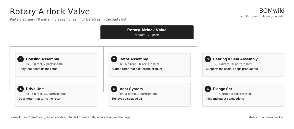
| # | Part | Qty | What it does |
|---|---|---|---|
| 1 | Housing Assembly 5 parts | 1× | Body that contains the rotor |
| 2 | Rotor Assembly 5 parts | 1× | Vaned rotor that carries the product |
| 3 | Bearing & Seal Assembly 5 parts | 1× | Supports the shaft, keeps product out |
| 4 | Drive Unit 5 parts | 1× | Gearmotor that turns the rotor |
| 5 | Vent System 3 parts | 1× | Relieves displaced air |
| 6 | Flange Set 4 parts | 1× | Inlet and outlet connections |
3D model
No 3D model yet. Have a CAD file of this? Add a 3D model — STL renders right on this page; STEP, FreeCAD, and OpenSCAD sources are welcome too (openly licensed, like all 3D models on BOMwiki).
Build & assembly graph
expand / collapse · shared sub-assemblies converge · links to related products · est. labourTap an assembly to expand/collapse · tap a part to open it · use “Open page” for any node · drag to pan, scroll to zoom.
Bill of materials for Rotary Airlock Valve
6 top-level lines · 39 rows shown · 78 parts total · indented to 3 levels| # | Item / sub-assembly | Part no. | Qty/assy | Ext. qty | Parts | Type |
|---|---|---|---|---|---|---|
| 1 | Housing Assembly 5 parts | rotary-airlock-valve-housing-assembly | 1× | 1 | 7 | assembly |
| 1.1 | Valve Body | rotary-airlock-valve-body | 1× | 1 | · | part |
| 1.2 | End Cover | rotary-airlock-valve-end-cover | 2× | 2 | · | part |
| 1.3 | Wear Liner | rotary-airlock-valve-housing-liner | 1× | 1 | · | part |
| 1.4 | Cover Gasket | rotary-airlock-valve-cover-gasket | 2× | 2 | · | part |
| 1.5 | Fastener Set | fastener-set | 1× | 1 | · | part |
| 2 | Rotor Assembly 5 parts | rotary-airlock-valve-rotor-assembly | 1× | 1 | 20 | assembly |
| 2.1 | Rotor Hub | rotary-airlock-valve-rotor-hub | 1× | 1 | · | part |
| 2.2 | Rotor Vane | rotary-airlock-valve-rotor-vane | 8× | 8 | · | part |
| 2.3 | Vane Tip Seal | rotary-airlock-valve-vane-tip | 8× | 8 | · | part |
| 2.4 | Rotor Shaft | rotary-airlock-valve-rotor-shaft | 1× | 1 | · | part |
| 2.5 | Shaft Key | rotary-airlock-valve-shaft-key | 2× | 2 | · | part |
| 3 | Bearing & Seal Assembly 5 parts | rotary-airlock-valve-bearing-seal-assembly | 1× | 1 | 10 | assembly |
| 3.1 | Ball Bearing | ball-bearing | 2× | 2 | · | part |
| 3.2 | Bearing Housing | rotary-airlock-valve-bearing-housing | 2× | 2 | · | part |
| 3.3 | Shaft Seal | rotary-airlock-valve-shaft-seal | 2× | 2 | · | part |
| 3.4 | Air Purge Port | rotary-airlock-valve-air-purge-port | 2× | 2 | · | part |
| 3.5 | Seal Spacer | rotary-airlock-valve-seal-spacer | 2× | 2 | · | part |
| 4 | Drive Unit 5 parts | rotary-airlock-valve-drive-unit | 1× | 1 | 33 | assembly |
| 4.1 | Helical Gearmotor 6 parts | rotary-airlock-valve-gearmotor | 1× | 1 | 28 | assembly |
| 4.1.1 | Stator Assembly 3 parts + deeper › | stator-assembly | 1× | 1 | 3 | assembly |
| 4.1.2 | Rotor Assembly 4 parts + deeper › | rotor-assembly | 1× | 1 | 19 | assembly |
| 4.1.3 | Helical Gear Pair | gear-pair | 1× | 1 | · | part |
| 4.1.4 | Gearbox Housing | gearbox-housing | 1× | 1 | · | part |
| 4.1.5 | Ball Bearing | ball-bearing | 2× | 2 | · | part |
| 4.1.6 | Oil Seal | oil-seal | 2× | 2 | · | part |
| 4.2 | Roller Chain | rotary-airlock-valve-chain-coupling | 1× | 1 | · | part |
| 4.3 | Drive Sprocket | rotary-airlock-valve-drive-sprocket | 2× | 2 | · | part |
| 4.4 | Chain Guard | rotary-airlock-valve-chain-guard | 1× | 1 | · | part |
| 4.5 | Overload Slip Clutch | rotary-airlock-valve-overload-clutch | 1× | 1 | · | part |
| 5 | Vent System 3 parts | rotary-airlock-valve-vent-system | 1× | 1 | 3 | assembly |
| 5.1 | Vent Port | rotary-airlock-valve-vent-port | 1× | 1 | · | part |
| 5.2 | Vent Pipe | rotary-airlock-valve-vent-pipe | 1× | 1 | · | part |
| 5.3 | Vent Filter | rotary-airlock-valve-vent-filter | 1× | 1 | · | part |
| 6 | Flange Set 4 parts | rotary-airlock-valve-flange-set | 1× | 1 | 5 | assembly |
| 6.1 | Inlet Flange | rotary-airlock-valve-inlet-flange | 1× | 1 | · | part |
| 6.2 | Outlet Flange | rotary-airlock-valve-outlet-flange | 1× | 1 | · | part |
| 6.3 | Flange Gasket | rotary-airlock-valve-flange-gasket | 2× | 2 | · | part |
| 6.4 | Fastener Set | fastener-set | 1× | 1 | · | part |
Sourcing: possible vendors
Prices, MOQ, and lead times are algorithmic estimates, not quotes, and not claims about these companies. Company mappings are curated by keyword; est. price band $2k–$300k. How estimates work| Vendor | HQ | Specialty | MOQ | Lead time |
|---|---|---|---|---|
| toyota-industries.com ↗ | Kariya, JP | Forklifts & logistics | 20 units | 10–16 wks |
| kiongroup.com ↗ | Frankfurt, DE | Forklifts (Linde, STILL) | 20 units | 10–16 wks |
| jungheinrich.com ↗ | Hamburg, DE | Warehouse trucks | 20 units | 10–16 wks |
| crown.com ↗ | New Bremen, US | Forklifts | 20 units | 10–16 wks |
|
🇨🇳Hangcha
hcforklift.com ↗
|
Hangzhou, CN | Forklifts & material handling | 20 units | 10–16 wks |
891-word article