Pallet Shuttle System
ProductOverview
A pallet shuttle system is a battery-powered, radio-controlled cart that runs inside deep storage channels in a pallet-racking structure. It carries no operator. A forklift or stacker crane places the shuttle into the entry position of a channel, and from there the cart drives itself along a pair of rails that run the full depth of the lane. The shuttle slides beneath a pallet, raises it a few centimetres off the supporting rails with its lifting deck, and carries it to a free position or back to the channel mouth. This approach lets a single lane hold a continuous row of pallets with no aisle between them, which raises storage density well above conventional selective racking.
Shuttle systems are used for high-volume storage of uniform goods: beverages, canned food, frozen products, paper reels, and similar palletised stock. They suit both first-in-first-out and last-in-first-out flows depending on whether the channel is loaded from one end or two. Because the cart does the in-lane travel, the lift truck only handles the channel entry, so truck movement and aisle space both fall.
Chassis and frame
The chassis is a welded steel structure kept under 200 mm tall so the whole cart fits in the gap between the rail tops and the bottom of a seated pallet. The base frame weldment carries every other subsystem and takes the full pallet weight through the top cover plate when the deck is lowered. Folded side skirts shield the wheels and wiring from debris that collects in storage channels. Four guide rollers with polyurethane tyres run against the side faces of the channel rails and keep the cart centred, which stops the running wheels from rubbing or climbing the rail edge during travel.
Traction drive
The traction drive moves the loaded cart along the channel at 0.5-1.0 m/s. A geared brushless motor of 0.75-1.5 kW feeds a planetary Helical Gearbox that turns the drive axle. Two of the four running wheels are powered through that axle, and a toothed Drive Belt links them to the idler wheels so the cart tracks straight under load. The wheels are steel-rimmed with a flat tread matched to the rail width, and they ride on ball bearings sized for the rated 1,000-1,500 kg pallet plus the cart mass. A spring-applied parking brake grips the axle whenever power is removed, so the cart holds position on a slight grade or during a power loss rather than rolling free.
Lifting deck
The lifting deck raises the pallet 25-50 mm clear of the channel rails so the cart can carry it. A dedicated lift motor turns a ball screw that drives a carriage along two linear guides. The carriage pushes four wedge cam blocks horizontally, and the cam follower rollers under the lift platform ride up the cam ramps. Converting horizontal screw travel into a short vertical lift gives a high mechanical advantage, which is why a modest 0.5-1.0 kW motor can raise a full pallet in 2-4 seconds. Four return springs pull the deck back down if power is cut mid-lift, so a stalled cart lowers its load onto the rails rather than dropping it.
Battery pack and BMS
Power comes from a lithium-ion pack built from 21700 cells in a series-parallel array, giving 24-48 VDC at 30-50 Ah. High-discharge cells are used because the traction and lift motors draw heavy peak current during acceleration and during a lift cycle. A battery management board tracks each cell group for voltage and temperature, balances the cells during charge, and cuts the pack on over-current or over-discharge. A pressure sensor in the pack watches for cell venting so a thermal fault can be flagged early. The cells sit in a sealed, finned aluminium enclosure and are joined by a spot-welded nickel busbar set. A typical pack supports 300-600 pallet moves before it needs a recharge.
Control electronics and positioning
The control unit runs the cart. Its motion control board uses an ARM controller for travel and lift sequencing and an application processor for the fleet protocol that ties many shuttles to one warehouse management system. Two motor drive modules, each built around an IGBT power module with a DC-link capacitor and Encoder feedback, deliver controlled three-phase current to the traction and lift motors. An RF receiver with its antenna takes store and retrieve commands from a handheld remote or from the warehouse system over a 2.4 GHz link. A DC-DC converter steps the pack voltage down to the logic and sensor rails.
The sensor suite tells the controller where the cart is and whether a pallet is present. Two channel position sensors count rail features or floor markers, and an Encoder on the drive axle measures travel distance, so the cart knows how far it has run into the lane. Four pallet presence sensors confirm a pallet is correctly seated before the deck lifts and remains seated during transport. Limit switches mark the ends of the channel and the lift travel limits. Combining the encoder count with the position markers lets the cart stop at a precise pallet slot and detect the last occupied position when consolidating a lane.
Safety and charging
The safety system stops the cart if it meets an obstruction. Front and rear impact bumpers on compliance springs trip a switch on contact, and two obstacle sensors scan the channel ahead. A latching emergency stop and a safety Relay cut motor power directly when tripped, independent of the firmware. Recharging uses the charging interface: sprung contact plates meet fixed electrodes at the channel mouth, and a charge controller regulates current into the pack and guards against arcing as the plates engage. This opportunity charging keeps the cart in service through a shift, with a full charge taking 1-2 hours when the shuttle is parked.
Pallet Shuttle System parts and their functions
8 top-level parts · 208 parts in total · full bill of materials below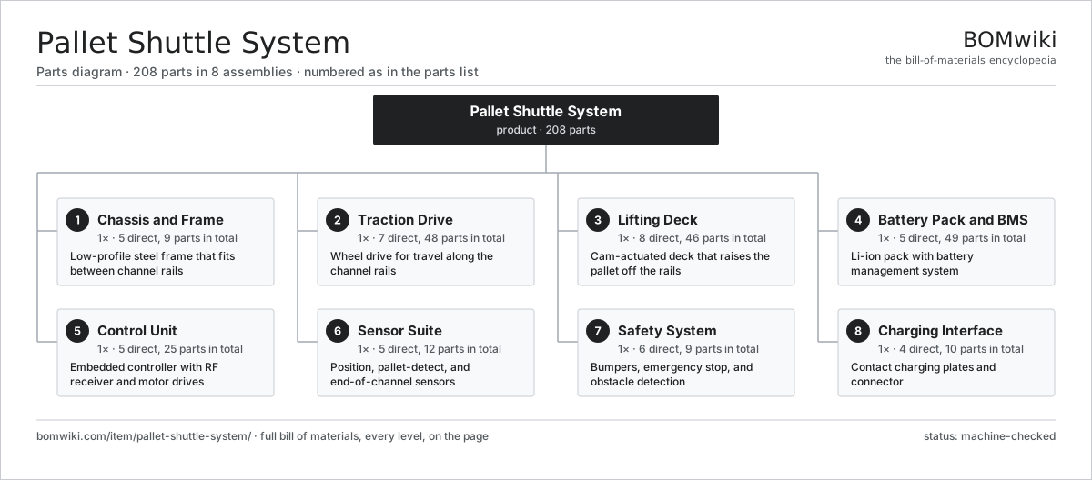
| # | Part | Qty | What it does |
|---|---|---|---|
| 1 | Chassis and Frame 5 parts | 1× | Low-profile steel frame that fits between channel rails |
| 2 | Traction Drive 7 parts | 1× | Wheel drive for travel along the channel rails |
| 3 | Lifting Deck 8 parts | 1× | Cam-actuated deck that raises the pallet off the rails |
| 4 | Battery Pack and BMS 5 parts | 1× | Li-ion pack with battery management system |
| 5 | Control Unit 5 parts | 1× | Embedded controller with RF receiver and motor drives |
| 6 | Sensor Suite 5 parts | 1× | Position, pallet-detect, and end-of-channel sensors |
| 7 | Safety System 6 parts | 1× | Bumpers, emergency stop, and obstacle detection |
| 8 | Charging Interface 4 parts | 1× | Contact charging plates and connector |
3D model
No 3D model yet. Have a CAD file of this? Add a 3D model — STL renders right on this page; STEP, FreeCAD, and OpenSCAD sources are welcome too (openly licensed, like all 3D models on BOMwiki).
Build & assembly graph
expand / collapse · shared sub-assemblies converge · links to related products · est. labourTap an assembly to expand/collapse · tap a part to open it · use “Open page” for any node · drag to pan, scroll to zoom.
Bill of materials for Pallet Shuttle System
8 top-level lines · 89 rows shown · 208 parts total · indented to 3 levels| # | Item / sub-assembly | Part no. | Qty/assy | Ext. qty | Parts | Type |
|---|---|---|---|---|---|---|
| 1 | Chassis and Frame 5 parts | pallet-shuttle-system-chassis | 1× | 1 | 9 | assembly |
| 1.1 | Base Frame Weldment | pallet-shuttle-system-base-frame | 1× | 1 | · | part |
| 1.2 | Side Skirt Panel | pallet-shuttle-system-side-skirt | 2× | 2 | · | part |
| 1.3 | Top Cover Plate | pallet-shuttle-system-top-cover | 1× | 1 | · | part |
| 1.4 | Channel Guide Roller | pallet-shuttle-system-guide-roller | 4× | 4 | · | part |
| 1.5 | Fastener Set | fastener-set | 1× | 1 | · | part |
| 2 | Traction Drive 7 parts | pallet-shuttle-system-traction-drive | 1× | 1 | 48 | assembly |
| 2.1 | Servo Motor 4 parts | servo-motor | 1× | 1 | 24 | assembly |
| 2.1.1 | Stator Assembly 3 parts + deeper › | stator-assembly | 1× | 1 | 3 | assembly |
| 2.1.2 | Rotor Assembly 4 parts + deeper › | rotor-assembly | 1× | 1 | 19 | assembly |
| 2.1.3 | Encoder | encoder | 1× | 1 | · | part |
| 2.1.4 | Motor Housing | motor-housing | 1× | 1 | · | part |
| 2.2 | Helical Gearbox 4 parts | gearbox | 1× | 1 | 9 | assembly |
| 2.2.1 | Helical Gear Pair | gear-pair | 2× | 2 | · | part |
| 2.2.2 | Gearbox Housing | gearbox-housing | 1× | 1 | · | part |
| 2.2.3 | Ball Bearing | ball-bearing | 4× | 4 | · | part |
| 2.2.4 | Oil Seal | oil-seal | 2× | 2 | · | part |
| 2.3 | Drive Axle | pallet-shuttle-system-drive-axle | 1× | 1 | · | part |
| 2.4 | Running Wheel | pallet-shuttle-system-running-wheel | 4× | 4 | · | part |
| 2.5 | Drive Belt | drive-belt | 1× | 1 | · | part |
| 2.6 | Ball Bearing | ball-bearing | 8× | 8 | · | part |
| 2.7 | Parking Brake | pallet-shuttle-system-wheel-brake | 1× | 1 | · | part |
| 3 | Lifting Deck 8 parts | pallet-shuttle-system-lift-deck | 1× | 1 | 46 | assembly |
| 3.1 | Lift Platform | pallet-shuttle-system-lift-platform | 1× | 1 | · | part |
| 3.2 | Wedge Cam Block | pallet-shuttle-system-wedge-cam | 4× | 4 | · | part |
| 3.3 | Servo Motor 4 parts | servo-motor | 1× | 1 | 24 | assembly |
| 3.3.1 | Stator Assembly 3 parts + deeper › | stator-assembly | 1× | 1 | 3 | assembly |
| 3.3.2 | Rotor Assembly 4 parts + deeper › | rotor-assembly | 1× | 1 | 19 | assembly |
| 3.3.3 | Encoder | encoder | 1× | 1 | · | part |
| 3.3.4 | Motor Housing | motor-housing | 1× | 1 | · | part |
| 3.4 | Ball Screw | ball-screw | 1× | 1 | · | part |
| 3.5 | Linear Guide Rail | linear-guide | 2× | 2 | · | part |
| 3.6 | Cam Follower Roller | pallet-shuttle-system-lift-roller | 8× | 8 | · | part |
| 3.7 | Coil Spring | coil-spring | 4× | 4 | · | part |
| 3.8 | Ball Bearing | ball-bearing | 2× | 2 | · | part |
| 4 | Battery Pack and BMS 5 parts | pallet-shuttle-system-battery-pack | 1× | 1 | 49 | assembly |
| 4.1 | Li-ion Cell, 21700 | li-cell-21700 | 40× | 40 | · | part |
| 4.2 | Battery Management Board 5 parts | pallet-shuttle-system-bms-board | 1× | 1 | 5 | assembly |
| 4.2.1 | Bare PCB | pcb-bare | 1× | 1 | · | part |
| 4.2.2 | Microcontroller | mcu | 1× | 1 | · | part |
| 4.2.3 | SMD Passive (R/C/L) | smd-passives | 1× | 1 | · | part |
| 4.2.4 | Pressure Sensor | pressure-sensor | 1× | 1 | · | part |
| 4.2.5 | Connector | connector | 1× | 1 | · | part |
| 4.3 | Pack Enclosure | pallet-shuttle-system-pack-enclosure | 1× | 1 | · | part |
| 4.4 | Cell Busbar Set | pallet-shuttle-system-cell-busbar | 1× | 1 | · | part |
| 4.5 | Connector | connector | 2× | 2 | · | part |
| 5 | Control Unit 5 parts | pallet-shuttle-system-control-unit | 1× | 1 | 25 | assembly |
| 5.1 | Motion Control Board 5 parts | pallet-shuttle-system-main-board | 1× | 1 | 6 | assembly |
| 5.1.1 | Microcontroller | mcu | 1× | 1 | · | part |
| 5.1.2 | Compute SoC Module | soc-module | 1× | 1 | · | part |
| 5.1.3 | Bare PCB | pcb-bare | 1× | 1 | · | part |
| 5.1.4 | SMD Passive (R/C/L) | smd-passives | 1× | 1 | · | part |
| 5.1.5 | Relay | relay | 2× | 2 | · | part |
| 5.2 | Motor Drive Module 5 parts | pallet-shuttle-system-motor-driver | 2× | 2 | 5 | assembly |
| 5.2.1 | IGBT Power Module | igbt-module | 1× | 2 | · | part |
| 5.2.2 | DC-Link Capacitor | dc-link-cap | 1× | 2 | · | part |
| 5.2.3 | Bare PCB | pcb-bare | 1× | 2 | · | part |
| 5.2.4 | Encoder | encoder | 1× | 2 | · | part |
| 5.2.5 | SMD Passive (R/C/L) | smd-passives | 1× | 2 | · | part |
| 5.3 | RF Receiver Module 4 parts | pallet-shuttle-system-rf-receiver | 1× | 1 | 4 | assembly |
| 5.3.1 | Compute SoC Module | soc-module | 1× | 1 | · | part |
| 5.3.2 | Bare PCB | pcb-bare | 1× | 1 | · | part |
| 5.3.3 | Radio Antenna | pallet-shuttle-system-antenna | 1× | 1 | · | part |
| 5.3.4 | Connector | connector | 1× | 1 | · | part |
| 5.4 | Power Supply | power-supply | 1× | 1 | · | part |
| 5.5 | Connector | connector | 4× | 4 | · | part |
| 6 | Sensor Suite 5 parts | pallet-shuttle-system-sensor-suite | 1× | 1 | 12 | assembly |
| 6.1 | Channel Position Sensor | pallet-shuttle-system-position-sensor | 2× | 2 | · | part |
| 6.2 | Pallet Presence Sensor | pallet-shuttle-system-pallet-detector | 4× | 4 | · | part |
| 6.3 | Limit Switch | limit-switch | 4× | 4 | · | part |
| 6.4 | Encoder | encoder | 1× | 1 | · | part |
| 6.5 | Wire Bundle | wire-bundle | 1× | 1 | · | part |
| 7 | Safety System 6 parts | pallet-shuttle-system-safety-system | 1× | 1 | 9 | assembly |
| 7.1 | Impact Bumper | pallet-shuttle-system-bumper | 2× | 2 | · | part |
| 7.2 | Emergency Stop Switch | pallet-shuttle-system-estop-switch | 1× | 1 | · | part |
| 7.3 | Obstacle Sensor | pallet-shuttle-system-obstacle-sensor | 2× | 2 | · | part |
| 7.4 | Coil Spring | coil-spring | 2× | 2 | · | part |
| 7.5 | Relay | relay | 1× | 1 | · | part |
| 7.6 | Wire Bundle | wire-bundle | 1× | 1 | · | part |
| 8 | Charging Interface 4 parts | pallet-shuttle-system-charging-interface | 1× | 1 | 10 | assembly |
| 8.1 | Charging Contact Plate | pallet-shuttle-system-contact-plate | 2× | 2 | · | part |
| 8.2 | Charge Controller Board 5 parts | pallet-shuttle-system-charge-controller | 1× | 1 | 5 | assembly |
| 8.2.1 | Bare PCB | pcb-bare | 1× | 1 | · | part |
| 8.2.2 | Microcontroller | mcu | 1× | 1 | · | part |
| 8.2.3 | Relay | relay | 1× | 1 | · | part |
| 8.2.4 | SMD Passive (R/C/L) | smd-passives | 1× | 1 | · | part |
| 8.2.5 | Connector | connector | 1× | 1 | · | part |
| 8.3 | Coil Spring | coil-spring | 2× | 2 | · | part |
| 8.4 | Connector | connector | 1× | 1 | · | part |
Related products
same domain, ranked by shared parts Reach Truck
832 parts · shares 12 with this page
Reach Truck
832 parts · shares 12 with this page
 Articulated Forklift
2,417 parts · shares 10 with this page
Articulated Forklift
2,417 parts · shares 10 with this page
 Bag Palletizer
951 parts · shares 10 with this page
Bag Palletizer
951 parts · shares 10 with this page
 Layer Palletizer
857 parts · shares 10 with this page
Layer Palletizer
857 parts · shares 10 with this page
 Vertical Lift Module
978 parts · shares 9 with this page
Vertical Lift Module
978 parts · shares 9 with this page
Sourcing: possible vendors
Prices, MOQ, and lead times are algorithmic estimates, not quotes, and not claims about these companies. Company mappings are curated by keyword; est. price band $2k–$300k. How estimates work| Vendor | HQ | Specialty | MOQ | Lead time |
|---|---|---|---|---|
| toyota-industries.com ↗ | Kariya, JP | Forklifts & logistics | 20 units | 10–16 wks |
| kiongroup.com ↗ | Frankfurt, DE | Forklifts (Linde, STILL) | 20 units | 10–16 wks |
| jungheinrich.com ↗ | Hamburg, DE | Warehouse trucks | 20 units | 10–16 wks |
| crown.com ↗ | New Bremen, US | Forklifts | 20 units | 10–16 wks |
|
🇨🇳Hangcha
hcforklift.com ↗
|
Hangzhou, CN | Forklifts & material handling | 20 units | 10–16 wks |
1,198-word article