Rubber-Tyred Gantry Crane
ProductOverview
A rubber-tyred gantry crane, or RTG, stacks shipping containers in the storage blocks of a port without running on fixed rails. It is a portal: a steel frame that straddles several rows of containers plus a truck lane, with a hoist that runs across the top and lifts boxes down onto a road chassis or up onto a stack. Because it rolls on rubber tires rather than rails, an RTG can be driven to a different block as traffic shifts, which makes a terminal's yard layout flexible in a way a rail-mounted crane is not. A typical RTG spans six or seven rows of containers and stacks them five or six high.
The Gantry Structure is the portal frame, the Gantry Travel System system moves the whole crane, the Hoist Machinery raises and lowers the load, the Trolley positions it across the span, the Spreader grips the box, the Power and Drive system supplies energy, and the Control and Automation system coordinates everything from the Operator Cab.
Structure and travel
The Gantry Structure is a rigid portal of four Gantry Leg columns tied by Sill Beam beams at the bottom and two Top Girder girders at the top, squared by Tie Beam cross beams. What makes the crane mobile is the Gantry Travel System system: each corner sits on a Wheel Bogie that equalizes the load across four Crane Tire tires, sixteen in all, each driven by a geared Travel Drive Motor. To move from one block to another, a Steering Unit rotates the bogies ninety degrees so the crane crabs sideways across the yard, and Travel Brake units hold it in place while it works.
Hoist and trolley
Lifting is done by the Hoist Machinery. A variable-speed Hoist Motor drives a Hoist Gearbox and a pair of Rope Drum drums, which spool Wire Rope wire ropes reeved over Sheave pulleys down to the spreader. A fail-safe Hoist Brake holds the load if power is lost, and an Encoder on the motor reports drum rotation for height and anti-sway control. The Trolley carries the sheaves and runs along the top girder on Trolley Wheel wheels driven by Trolley Drive Motor motors, positioning the load across the span. A Festoon Cable System cable carrier feeds power and signals to the moving trolley.
Spreader
The Spreader hangs from the ropes and grips a container the same way the spreader on a handler does, with four Twistlock cones turned by Twistlock Cylinder rams into the corner castings. A Spreader Frame telescopes on Telescope Cylinder rams to fit 20 ft and 40 ft boxes, Guide Flipper guides funnel it onto the box, and a Landing Sensor at each corner confirms seating before the locks turn. Because the spreader hangs far from the machinery, a local Spreader Power Unit unit with its own Spreader Pump supplies the spreader hydraulics.
Power and drives
An RTG needs no fixed conductor rail, so it carries its own power. The Power and Drive system is usually a Diesel Generator Set with a Diesel Engine driving a Generator, though many cranes now add a Shore-Power Connection to run on grid power and cut fuel and emissions. Power feeds a Drive Cabinet of Variable-Frequency Drive variable-frequency drives that control the hoist, trolley, and travel motors. When the operator lowers a box, the hoist motor acts as a generator, and a Braking Resistor dumps that energy, or on a shore-connected crane it can be returned to the grid.
Control and automation
The Control and Automation system turns separate motions into a clean pick and place. A Crane PLC sequences hoist, trolley, gantry, and spreader interlocks, while an Anti-Sway System system reads a Sway Sensor and shapes the motion so the load does not swing as the trolley accelerates and stops. Because a rubber-tired crane has no rails to keep it straight, a Position System with Laser Scanner scanners and a GNSS Unit holds the crane aligned along a row and steers it accurately between blocks. Load Cell sensors in the reeving weigh the load. The operator works from a trolley-mounted Operator Cab with a downward floor window that looks straight at the pick.
Use and place in the fleet
RTGs are the standard yard-stacking crane of most container terminals because they combine high stacking density with the freedom to relocate between blocks. They lift full boxes that a Laden Container Handler handles only at the fringe of a block, and stack denser than any Empty Container Handler, while avoiding the fixed runway of a Rail-Mounted Gantry Crane. Their limits are the tire and pavement loads they impose, the diesel fuel burn when not shore-connected, and the need for accurate auto-steering to keep a tire-borne crane tracking straight. A terminal chooses RTGs when it wants dense stacking with a yard layout it can change, and switches to rail-mounted cranes only where the highest density and fully automated operation justify the rails.
Rubber-Tyred Gantry Crane parts and their functions
8 top-level parts · 1,417 parts in total · full bill of materials below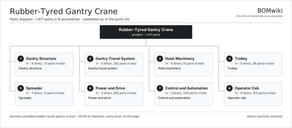
| # | Part | Qty | What it does |
|---|---|---|---|
| 1 | Gantry Structure 6 parts | 1× | Gantry structure |
| 2 | Gantry Travel System 5 parts | 1× | Gantry travel system |
| 3 | Hoist Machinery 6 parts | 1× | Hoist machinery |
| 4 | Trolley 5 parts | 1× | Trolley |
| 5 | Spreader 7 parts | 1× | Spreader |
| 6 | Power and Drive 5 parts | 1× | Power and drive |
| 7 | Control and Automation 5 parts | 1× | Control and automation |
| 8 | Operator Cab 6 parts | 1× | Operator cab |
3D model
No 3D model yet. Have a CAD file of this? Add a 3D model — STL renders right on this page; STEP, FreeCAD, and OpenSCAD sources are welcome too (openly licensed, like all 3D models on BOMwiki).
Build & assembly graph
expand / collapse · shared sub-assemblies converge · links to related products · est. labourTap an assembly to expand/collapse · tap a part to open it · use “Open page” for any node · drag to pan, scroll to zoom.
Bill of materials for Rubber-Tyred Gantry Crane
8 top-level lines · 105 rows shown · 1,417 parts total · indented to 3 levels| # | Item / sub-assembly | Part no. | Qty/assy | Ext. qty | Parts | Type |
|---|---|---|---|---|---|---|
| 1 | Gantry Structure 6 parts | rubber-tyred-gantry-crane-structure | 1× | 1 | 13 | assembly |
| 1.1 | Gantry Leg | rubber-tyred-gantry-crane-leg | 4× | 4 | · | part |
| 1.2 | Sill Beam | rubber-tyred-gantry-crane-sill-beam | 2× | 2 | · | part |
| 1.3 | Top Girder | rubber-tyred-gantry-crane-top-girder | 2× | 2 | · | part |
| 1.4 | Tie Beam | rubber-tyred-gantry-crane-tie-beam | 2× | 2 | · | part |
| 1.5 | Access Ladder | rubber-tyred-gantry-crane-ladder | 2× | 2 | · | part |
| 1.6 | Fastener Set | fastener-set | 1× | 1 | · | part |
| 2 | Gantry Travel System 5 parts | rubber-tyred-gantry-crane-travel | 1× | 1 | 292 | assembly |
| 2.1 | Wheel Bogie 3 parts | rubber-tyred-gantry-crane-bogie | 4× | 4 | 13 | assembly |
| 2.1.1 | Bogie Frame | rubber-tyred-gantry-crane-bogie-frame | 1× | 4 | · | part |
| 2.1.2 | Crane Tire | rubber-tyred-gantry-crane-tire | 4× | 16 | · | part |
| 2.1.3 | Ball Bearing | ball-bearing | 8× | 32 | · | part |
| 2.2 | Travel Drive Motor 5 parts | rubber-tyred-gantry-crane-travel-motor | 8× | 8 | 26 | assembly |
| 2.2.1 | Stator Assembly 3 parts + deeper › | stator-assembly | 1× | 8 | 3 | assembly |
| 2.2.2 | Rotor Assembly 4 parts + deeper › | rotor-assembly | 1× | 8 | 19 | assembly |
| 2.2.3 | Gearbox Housing | gearbox-housing | 1× | 8 | · | part |
| 2.2.4 | Helical Gear Pair | gear-pair | 1× | 8 | · | part |
| 2.2.5 | Ball Bearing | ball-bearing | 2× | 16 | · | part |
| 2.3 | Crane Tire | rubber-tyred-gantry-crane-tire | 16× | 16 | · | part |
| 2.4 | Steering Unit 2 parts | rubber-tyred-gantry-crane-steer-unit | 4× | 4 | 2 | assembly |
| 2.4.1 | Steer Cylinder | rubber-tyred-gantry-crane-steer-cylinder | 1× | 4 | · | part |
| 2.4.2 | Slew Bearing | rubber-tyred-gantry-crane-slew-bearing | 1× | 4 | · | part |
| 2.5 | Travel Brake | rubber-tyred-gantry-crane-travel-brake | 8× | 8 | · | part |
| 3 | Hoist Machinery 6 parts | rubber-tyred-gantry-crane-hoist | 1× | 1 | 51 | assembly |
| 3.1 | Hoist Motor 5 parts | rubber-tyred-gantry-crane-hoist-motor | 1× | 1 | 26 | assembly |
| 3.1.1 | Stator Assembly 3 parts + deeper › | stator-assembly | 1× | 1 | 3 | assembly |
| 3.1.2 | Rotor Assembly 4 parts + deeper › | rotor-assembly | 1× | 1 | 19 | assembly |
| 3.1.3 | Motor Housing | motor-housing | 1× | 1 | · | part |
| 3.1.4 | Ball Bearing | ball-bearing | 2× | 2 | · | part |
| 3.1.5 | Encoder | rubber-tyred-gantry-crane-encoder | 1× | 1 | · | part |
| 3.2 | Hoist Gearbox 4 parts | rubber-tyred-gantry-crane-hoist-gearbox | 1× | 1 | 9 | assembly |
| 3.2.1 | Helical Gear Pair | gear-pair | 2× | 2 | · | part |
| 3.2.2 | Gearbox Housing | gearbox-housing | 1× | 1 | · | part |
| 3.2.3 | Ball Bearing | ball-bearing | 4× | 4 | · | part |
| 3.2.4 | Oil Seal | oil-seal | 2× | 2 | · | part |
| 3.3 | Rope Drum | rubber-tyred-gantry-crane-rope-drum | 2× | 2 | · | part |
| 3.4 | Wire Rope | rubber-tyred-gantry-crane-hoist-rope | 4× | 4 | · | part |
| 3.5 | Sheave | rubber-tyred-gantry-crane-sheave | 8× | 8 | · | part |
| 3.6 | Hoist Brake | rubber-tyred-gantry-crane-hoist-brake | 2× | 2 | · | part |
| 4 | Trolley 5 parts | rubber-tyred-gantry-crane-trolley | 1× | 1 | 58 | assembly |
| 4.1 | Trolley Frame | rubber-tyred-gantry-crane-trolley-frame | 1× | 1 | · | part |
| 4.2 | Trolley Wheel | rubber-tyred-gantry-crane-trolley-wheel | 4× | 4 | · | part |
| 4.3 | Trolley Drive Motor 4 parts | rubber-tyred-gantry-crane-trolley-motor | 2× | 2 | 25 | assembly |
| 4.3.1 | Stator Assembly 3 parts + deeper › | stator-assembly | 1× | 2 | 3 | assembly |
| 4.3.2 | Rotor Assembly 4 parts + deeper › | rotor-assembly | 1× | 2 | 19 | assembly |
| 4.3.3 | Helical Gear Pair | gear-pair | 1× | 2 | · | part |
| 4.3.4 | Ball Bearing | ball-bearing | 2× | 4 | · | part |
| 4.4 | Trolley Brake | rubber-tyred-gantry-crane-trolley-brake | 2× | 2 | · | part |
| 4.5 | Festoon Cable System | rubber-tyred-gantry-crane-festoon | 1× | 1 | · | part |
| 5 | Spreader 7 parts | rubber-tyred-gantry-crane-spreader | 1× | 1 | 21 | assembly |
| 5.1 | Spreader Frame | rubber-tyred-gantry-crane-spreader-frame | 1× | 1 | · | part |
| 5.2 | Twistlock | rubber-tyred-gantry-crane-twistlock | 4× | 4 | · | part |
| 5.3 | Twistlock Cylinder | rubber-tyred-gantry-crane-twistlock-cylinder | 4× | 4 | · | part |
| 5.4 | Telescope Cylinder | rubber-tyred-gantry-crane-telescope-cylinder | 2× | 2 | · | part |
| 5.5 | Guide Flipper | rubber-tyred-gantry-crane-flipper | 4× | 4 | · | part |
| 5.6 | Landing Sensor | rubber-tyred-gantry-crane-landing-sensor | 4× | 4 | · | part |
| 5.7 | Spreader Power Unit 2 parts | rubber-tyred-gantry-crane-spreader-power | 1× | 1 | 2 | assembly |
| 5.7.1 | Spreader Pump | rubber-tyred-gantry-crane-spreader-pump | 1× | 1 | · | part |
| 5.7.2 | O-Ring Set | oring-set | 1× | 1 | · | part |
| 6 | Power and Drive 5 parts | rubber-tyred-gantry-crane-power | 1× | 1 | 550 | assembly |
| 6.1 | Diesel Generator Set 4 parts | rubber-tyred-gantry-crane-genset | 1× | 1 | 4 | assembly |
| 6.1.1 | Diesel Engine | rubber-tyred-gantry-crane-genset-engine | 1× | 1 | · | part |
| 6.1.2 | Generator | rubber-tyred-gantry-crane-generator | 1× | 1 | · | part |
| 6.1.3 | Fuel Tank | rubber-tyred-gantry-crane-fuel-tank | 1× | 1 | · | part |
| 6.1.4 | Radiator | rubber-tyred-gantry-crane-radiator | 1× | 1 | · | part |
| 6.2 | Drive Cabinet 4 parts | rubber-tyred-gantry-crane-drive-cabinet | 1× | 1 | 542 | assembly |
| 6.2.1 | Variable-Frequency Drive 5 parts + deeper › | rubber-tyred-gantry-crane-vfd | 4× | 4 | 131 | assembly |
| 6.2.2 | Braking Resistor | rubber-tyred-gantry-crane-braking-resistor | 1× | 1 | · | part |
| 6.2.3 | Relay | relay | 16× | 16 | · | part |
| 6.2.4 | Wire Bundle | wire-bundle | 1× | 1 | · | part |
| 6.3 | Transformer | rubber-tyred-gantry-crane-transformer | 1× | 1 | · | part |
| 6.4 | Shore-Power Connection | rubber-tyred-gantry-crane-shore-connection | 1× | 1 | · | part |
| 6.5 | Power Supply | power-supply | 2× | 2 | · | part |
| 7 | Control and Automation 5 parts | rubber-tyred-gantry-crane-control | 1× | 1 | 330 | assembly |
| 7.1 | Crane PLC 5 parts | rubber-tyred-gantry-crane-plc | 1× | 1 | 217 | assembly |
| 7.1.1 | Bare PCB | pcb-bare | 1× | 1 | · | part |
| 7.1.2 | Microcontroller | mcu | 2× | 2 | · | part |
| 7.1.3 | CAN Transceiver | can-transceiver | 2× | 2 | · | part |
| 7.1.4 | SMD Passive (R/C/L) | smd-passives | 200× | 200 | · | part |
| 7.1.5 | Connector | connector | 12× | 12 | · | part |
| 7.2 | Anti-Sway System 4 parts | rubber-tyred-gantry-crane-anti-sway | 1× | 1 | 63 | assembly |
| 7.2.1 | Bare PCB | pcb-bare | 1× | 1 | · | part |
| 7.2.2 | Microcontroller | mcu | 1× | 1 | · | part |
| 7.2.3 | Sway Sensor | rubber-tyred-gantry-crane-sway-sensor | 1× | 1 | · | part |
| 7.2.4 | SMD Passive (R/C/L) | smd-passives | 60× | 60 | · | part |
| 7.3 | Position System 4 parts | rubber-tyred-gantry-crane-position-system | 1× | 1 | 5 | assembly |
| 7.3.1 | Laser Scanner | rubber-tyred-gantry-crane-laser-scanner | 2× | 2 | · | part |
| 7.3.2 | GNSS Unit | rubber-tyred-gantry-crane-gps-unit | 1× | 1 | · | part |
| 7.3.3 | Bare PCB | pcb-bare | 1× | 1 | · | part |
| 7.3.4 | Microcontroller | mcu | 1× | 1 | · | part |
| 7.4 | Load Cell | rubber-tyred-gantry-crane-load-cell | 4× | 4 | · | part |
| 7.5 | Control Harness 2 parts | rubber-tyred-gantry-crane-harness | 1× | 1 | 41 | assembly |
| 7.5.1 | Wire Bundle | wire-bundle | 1× | 1 | · | part |
| 7.5.2 | Connector | connector | 40× | 40 | · | part |
| 8 | Operator Cab 6 parts | rubber-tyred-gantry-crane-cab | 1× | 1 | 102 | assembly |
| 8.1 | Cab Shell | rubber-tyred-gantry-crane-cab-shell | 1× | 1 | · | part |
| 8.2 | Operator Seat | rubber-tyred-gantry-crane-seat | 1× | 1 | · | part |
| 8.3 | Control Joystick | rubber-tyred-gantry-crane-joystick | 2× | 2 | · | part |
| 8.4 | Operator Display 4 parts | rubber-tyred-gantry-crane-display | 1× | 1 | 93 | assembly |
| 8.4.1 | LCD Panel | lcd-panel | 1× | 1 | · | part |
| 8.4.2 | Bare PCB | pcb-bare | 1× | 1 | · | part |
| 8.4.3 | Microcontroller | mcu | 1× | 1 | · | part |
| 8.4.4 | SMD Passive (R/C/L) | smd-passives | 90× | 90 | · | part |
| 8.5 | Cab HVAC | rubber-tyred-gantry-crane-hvac | 1× | 1 | · | part |
| 8.6 | Glazing | rubber-tyred-gantry-crane-glass | 4× | 4 | · | part |
Related products
same domain, ranked by shared parts Rail-Mounted Gantry Crane
1,474 parts · shares 8 with this page
Rail-Mounted Gantry Crane
1,474 parts · shares 8 with this page
 Articulated Forklift
2,417 parts · shares 7 with this page
Articulated Forklift
2,417 parts · shares 7 with this page
 Reach Truck
832 parts · shares 7 with this page
Reach Truck
832 parts · shares 7 with this page
 Vertical Lift Module
978 parts · shares 6 with this page
Turret Truck
664 parts · shares 6 with this page
Pallet Shuttle System
208 parts · shares 5 with this page
Vertical Lift Module
978 parts · shares 6 with this page
Turret Truck
664 parts · shares 6 with this page
Pallet Shuttle System
208 parts · shares 5 with this page
Sourcing: possible vendors
Prices, MOQ, and lead times are algorithmic estimates, not quotes, and not claims about these companies. Company mappings are curated by keyword; est. price band $2k–$300k. How estimates work| Vendor | HQ | Specialty | MOQ | Lead time |
|---|---|---|---|---|
| toyota-industries.com ↗ | Kariya, JP | Forklifts & logistics | 20 units | 10–16 wks |
| kiongroup.com ↗ | Frankfurt, DE | Forklifts (Linde, STILL) | 20 units | 10–16 wks |
| jungheinrich.com ↗ | Hamburg, DE | Warehouse trucks | 20 units | 10–16 wks |
| crown.com ↗ | New Bremen, US | Forklifts | 20 units | 10–16 wks |
|
🇨🇳Hangcha
hcforklift.com ↗
|
Hangzhou, CN | Forklifts & material handling | 20 units | 10–16 wks |
1,032-word article