Pneumatic Conveying System
ProductOverview
A pneumatic conveying system moves dry bulk material such as powder or granules through a sealed pipeline by entraining it in a stream of air. Instead of belts, chains, or screws, the only moving thing in the line is the air and the product it carries, which makes the route flexible: the pipe can climb walls, cross roads, and turn corners that a mechanical conveyor cannot follow. The system has an air mover to generate flow, a feed station to introduce material, a conveying line of pipe and bends, a receiving vessel to drop the product out, and a filtration unit to clean the spent air before it is vented.
Plants use pneumatic conveying because it is dust-tight, needs little floor space, and routes around obstacles. Cement works, plastics plants, food factories, and chemical sites all rely on it. The trade-off is that air is an inefficient carrier compared with a belt, so the power per tonne is higher and abrasive or fragile materials need careful handling.
Dilute phase and dense phase
The two operating regimes differ in how much air carries how much product. In dilute phase, a high air velocity of 18 to 30 m/s keeps the particles fully suspended, like dust in a wind. It tolerates almost any free-flowing material and runs at low pressure from a Roots blower, but the high velocity grinds abrasive powders and shatters fragile ones. In dense phase, the line runs slowly at 3 to 8 m/s and pushes the material along as moving slugs or a sliding bed at higher pressure, typically from a compressor. Dense phase is gentler and uses less air per tonne, but it needs a pressure vessel feeder and works best with materials that hold a slug together. The system here is built around dilute phase with a blower, the most common configuration.
Air mover
The air mover package is built around a Roots blower, a positive-displacement machine in which two tri-lobe rotors mesh inside a casing and trap air between the lobes and the wall. A timing gear pair keeps the rotors synchronized so they never touch. The blower delivers a steady airflow against the line resistance and is driven by a three-phase motor through a drive belt. Because the rotors clatter, the package carries an inlet silencer and a discharge silencer, plus a pressure relief valve to protect against a blocked line.
Feeding and the rotary valve
Getting powder into a pressurized airstream without leaking air is the job of the rotary airlock valve at the bottom of the feed hopper. A vaned rotor turns inside a close-fitting housing; each pocket fills with powder at the top, rotates around, and empties into the line at the bottom, while the vanes maintain a running seal against the pressure difference. A gearmotor turns the rotor at a controlled speed, which sets the feed rate. A bin vibrator on the hopper stops the powder from bridging, and level probes tell the controller when the hopper is full or empty.
Pipeline and routing
The conveying line is mostly straight pipe joined by quick-release couplings, but the long-radius bends take the abuse. At every elbow the abrasive product slams into the outer wall, so bends are cast or hardened to resist erosion and are the most replaced parts in the system. Where one source feeds several destinations, a diverter valve swings an internal tunnel to route the flow down a chosen branch under a pneumatic actuator.
Separation and filtration
At the destination the air-product mixture enters a cyclone separator, which spins the flow so the heavier particles are thrown outward and fall into the receiver hopper, discharging through a butterfly valve. The air still carries fine dust, so it passes through the filtration unit, where pleated cartridges catch particles down to a micron. The cartridges are cleaned on the run by pulse-jet valves that fire bursts of compressed air to shake the dust cake off into a collection hopper. The whole sequence is run by the control panel, where a PLC reads line pressure and adjusts the blower through a variable frequency drive to keep the conveying velocity in the right band.
Materials and wear
The material being conveyed sets most of the design choices. Abrasive powders such as cement, sand, and alumina drive hardened bends and chrome-lined valves, and they push designers toward dense phase to cut velocity. Fragile granules such as plastic pellets and sugar crystals break into fines at high speed, so they too favor lower velocity or a stepped pipe bore. Sticky or hygroscopic powders need dried air and smooth product paths to avoid build-up. Many fine organic and metal powders are also combustible, so a system handling flour, sugar, or aluminium dust is built to ATEX rules with explosion isolation valves, vent panels, and earthing throughout. Matching the conveying mode, the air velocity, the pipe material, and the bend type to the specific powder is what separates a system that runs for years from one that plugs, wears out, or fails its dust-explosion assessment.
Pneumatic Conveying System parts and their functions
6 top-level parts · 388 parts in total · full bill of materials below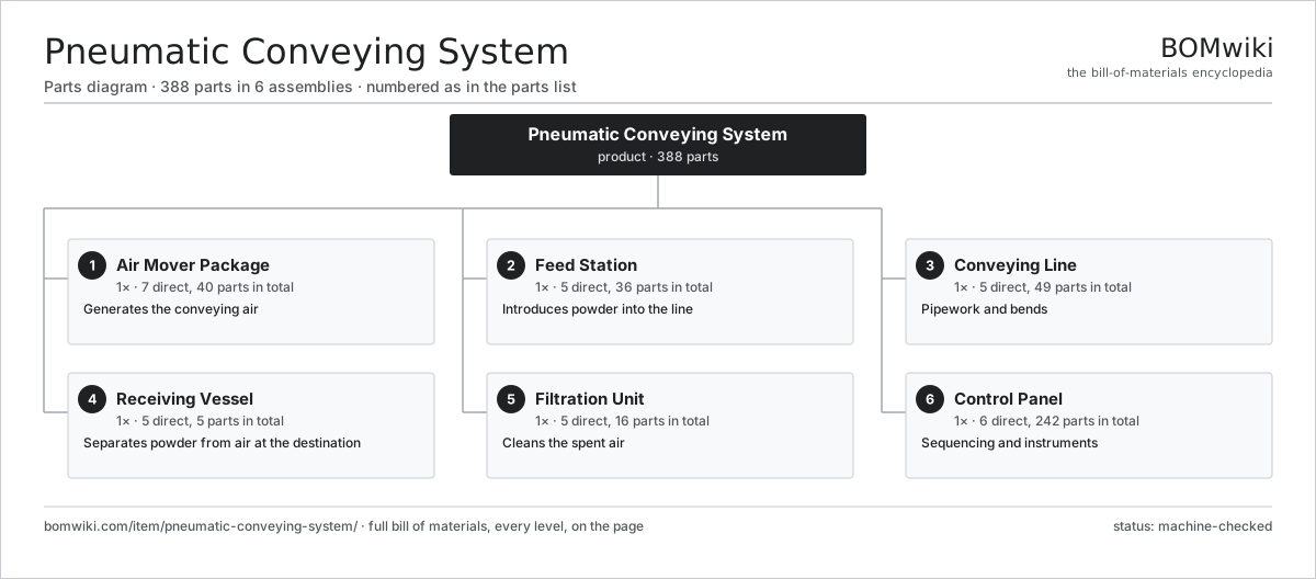
| # | Part | Qty | What it does |
|---|---|---|---|
| 1 | Air Mover Package 7 parts | 1× | Generates the conveying air |
| 2 | Feed Station 5 parts | 1× | Introduces powder into the line |
| 3 | Conveying Line 5 parts | 1× | Pipework and bends |
| 4 | Receiving Vessel 5 parts | 1× | Separates powder from air at the destination |
| 5 | Filtration Unit 5 parts | 1× | Cleans the spent air |
| 6 | Control Panel 6 parts | 1× | Sequencing and instruments |
3D model
No 3D model yet. Have a CAD file of this? Add a 3D model — STL renders right on this page; STEP, FreeCAD, and OpenSCAD sources are welcome too (openly licensed, like all 3D models on BOMwiki).
Build & assembly graph
expand / collapse · shared sub-assemblies converge · links to related products · est. labourTap an assembly to expand/collapse · tap a part to open it · use “Open page” for any node · drag to pan, scroll to zoom.
Bill of materials for Pneumatic Conveying System
6 top-level lines · 67 rows shown · 388 parts total · indented to 3 levels| # | Item / sub-assembly | Part no. | Qty/assy | Ext. qty | Parts | Type |
|---|---|---|---|---|---|---|
| 1 | Air Mover Package 7 parts | pneumatic-conveying-system-air-mover | 1× | 1 | 40 | assembly |
| 1.1 | Roots Blower 5 parts | pneumatic-conveying-system-roots-blower | 1× | 1 | 10 | assembly |
| 1.1.1 | Tri-Lobe Rotor | pneumatic-conveying-system-blower-rotor | 2× | 2 | · | part |
| 1.1.2 | Blower Casing | pneumatic-conveying-system-blower-casing | 1× | 1 | · | part |
| 1.1.3 | Helical Gear Pair | gear-pair | 1× | 1 | · | part |
| 1.1.4 | Ball Bearing | ball-bearing | 4× | 4 | · | part |
| 1.1.5 | Oil Seal | oil-seal | 2× | 2 | · | part |
| 1.2 | Blower Drive Motor 4 parts | pneumatic-conveying-system-blower-motor | 1× | 1 | 25 | assembly |
| 1.2.1 | Stator Assembly 3 parts + deeper › | stator-assembly | 1× | 1 | 3 | assembly |
| 1.2.2 | Rotor Assembly 4 parts + deeper › | rotor-assembly | 1× | 1 | 19 | assembly |
| 1.2.3 | Motor Housing | motor-housing | 1× | 1 | · | part |
| 1.2.4 | Ball Bearing | ball-bearing | 2× | 2 | · | part |
| 1.3 | Inlet Silencer | pneumatic-conveying-system-inlet-silencer | 1× | 1 | · | part |
| 1.4 | Discharge Silencer | pneumatic-conveying-system-discharge-silencer | 1× | 1 | · | part |
| 1.5 | Pressure Relief Valve | pneumatic-conveying-system-relief-valve | 1× | 1 | · | part |
| 1.6 | Non-Return Valve | pneumatic-conveying-system-non-return-valve | 1× | 1 | · | part |
| 1.7 | Drive Belt | drive-belt | 1× | 1 | · | part |
| 2 | Feed Station 5 parts | pneumatic-conveying-system-feed-station | 1× | 1 | 36 | assembly |
| 2.1 | Feed Hopper | pneumatic-conveying-system-feed-hopper | 1× | 1 | · | part |
| 2.2 | Rotary Airlock Valve 6 parts | pneumatic-conveying-system-rotary-valve | 1× | 1 | 31 | assembly |
| 2.2.1 | Vaned Rotor | pneumatic-conveying-system-rotor-vane | 1× | 1 | · | part |
| 2.2.2 | Valve Housing | pneumatic-conveying-system-valve-housing | 1× | 1 | · | part |
| 2.2.3 | Valve Gearmotor 4 parts + deeper › | pneumatic-conveying-system-valve-motor | 1× | 1 | 24 | assembly |
| 2.2.4 | Gearbox Housing | gearbox-housing | 1× | 1 | · | part |
| 2.2.5 | Ball Bearing | ball-bearing | 2× | 2 | · | part |
| 2.2.6 | Oil Seal | oil-seal | 2× | 2 | · | part |
| 2.3 | Protection Screen | pneumatic-conveying-system-screen-grate | 1× | 1 | · | part |
| 2.4 | Bin Vibrator | pneumatic-conveying-system-vibrator | 1× | 1 | · | part |
| 2.5 | Level Probe | pneumatic-conveying-system-level-probe | 2× | 2 | · | part |
| 3 | Conveying Line 5 parts | pneumatic-conveying-system-conveying-line | 1× | 1 | 49 | assembly |
| 3.1 | Conveying Pipe | pneumatic-conveying-system-conveying-pipe | 12× | 12 | · | part |
| 3.2 | Long-Radius Bend | pneumatic-conveying-system-long-radius-bend | 6× | 6 | · | part |
| 3.3 | Quick-Release Coupling | pneumatic-conveying-system-pipe-coupling | 18× | 18 | · | part |
| 3.4 | Diverter Valve 4 parts | pneumatic-conveying-system-diverter-valve | 1× | 1 | 5 | assembly |
| 3.4.1 | Diverter Body | pneumatic-conveying-system-diverter-body | 1× | 1 | · | part |
| 3.4.2 | Swing Tunnel | pneumatic-conveying-system-diverter-tunnel | 1× | 1 | · | part |
| 3.4.3 | Pneumatic Actuator | pneumatic-conveying-system-pneumatic-actuator | 1× | 1 | · | part |
| 3.4.4 | O-Ring Set | oring-set | 2× | 2 | · | part |
| 3.5 | Pipe Support Clamp | pneumatic-conveying-system-pipe-support | 8× | 8 | · | part |
| 4 | Receiving Vessel 5 parts | pneumatic-conveying-system-receiver | 1× | 1 | 5 | assembly |
| 4.1 | Cyclone Separator | pneumatic-conveying-system-cyclone | 1× | 1 | · | part |
| 4.2 | Receiver Hopper | pneumatic-conveying-system-receiver-hopper | 1× | 1 | · | part |
| 4.3 | Discharge Butterfly Valve | pneumatic-conveying-system-discharge-valve | 1× | 1 | · | part |
| 4.4 | Sight Glass | pneumatic-conveying-system-sight-glass | 1× | 1 | · | part |
| 4.5 | Pressure Sensor | pressure-sensor | 1× | 1 | · | part |
| 5 | Filtration Unit 5 parts | pneumatic-conveying-system-filtration | 1× | 1 | 16 | assembly |
| 5.1 | Filter Housing | pneumatic-conveying-system-filter-housing | 1× | 1 | · | part |
| 5.2 | Filter Cartridge | pneumatic-conveying-system-filter-cartridge | 8× | 8 | · | part |
| 5.3 | Pulse-Jet Valve | pneumatic-conveying-system-pulse-valve | 4× | 4 | · | part |
| 5.4 | Dust Collection Hopper | pneumatic-conveying-system-dust-collector | 1× | 1 | · | part |
| 5.5 | Pressure Sensor | pressure-sensor | 2× | 2 | · | part |
| 6 | Control Panel 6 parts | pneumatic-conveying-system-control-panel | 1× | 1 | 242 | assembly |
| 6.1 | PLC Controller 4 parts | pneumatic-conveying-system-plc | 1× | 1 | 134 | assembly |
| 6.1.1 | Bare PCB | pcb-bare | 1× | 1 | · | part |
| 6.1.2 | Microcontroller | mcu | 1× | 1 | · | part |
| 6.1.3 | Connector | connector | 12× | 12 | · | part |
| 6.1.4 | SMD Passive (R/C/L) | smd-passives | 120× | 120 | · | part |
| 6.2 | Variable Frequency Drive 5 parts | pneumatic-conveying-system-vfd | 1× | 1 | 99 | assembly |
| 6.2.1 | Bare PCB | pcb-bare | 1× | 1 | · | part |
| 6.2.2 | Power MOSFET | mosfet | 6× | 6 | · | part |
| 6.2.3 | Gate Driver IC | gate-driver-ic | 1× | 1 | · | part |
| 6.2.4 | Power Supply | power-supply | 1× | 1 | · | part |
| 6.2.5 | SMD Passive (R/C/L) | smd-passives | 90× | 90 | · | part |
| 6.3 | Emergency Stop Button | pneumatic-conveying-system-emergency-stop | 1× | 1 | · | part |
| 6.4 | Power Supply | power-supply | 1× | 1 | · | part |
| 6.5 | Relay | relay | 6× | 6 | · | part |
| 6.6 | Wire Bundle | wire-bundle | 1× | 1 | · | part |
Related products
same domain, ranked by shared parts Dilute-Phase Conveying System
509 parts · shares 7 with this page
Dilute-Phase Conveying System
509 parts · shares 7 with this page
 Cross-Belt Sorter
25,040 parts · shares 6 with this page
Cross-Belt Sorter
25,040 parts · shares 6 with this page
 Sliding-Shoe Sorter
4,321 parts · shares 6 with this page
Sliding-Shoe Sorter
4,321 parts · shares 6 with this page
 Tilt-Tray Sorter
6,031 parts · shares 6 with this page
Tilt-Tray Sorter
6,031 parts · shares 6 with this page
 Vertical Spiral Conveyor
2,482 parts · shares 6 with this page
Order Picker
708 parts · shares 6 with this page
Vertical Spiral Conveyor
2,482 parts · shares 6 with this page
Order Picker
708 parts · shares 6 with this page
Sourcing: possible vendors
Prices, MOQ, and lead times are algorithmic estimates, not quotes, and not claims about these companies. Company mappings are curated by keyword; est. price band $2k–$300k. How estimates work| Vendor | HQ | Specialty | MOQ | Lead time |
|---|---|---|---|---|
| toyota-industries.com ↗ | Kariya, JP | Forklifts & logistics | 20 units | 10–16 wks |
| kiongroup.com ↗ | Frankfurt, DE | Forklifts (Linde, STILL) | 20 units | 10–16 wks |
| jungheinrich.com ↗ | Hamburg, DE | Warehouse trucks | 20 units | 10–16 wks |
| crown.com ↗ | New Bremen, US | Forklifts | 20 units | 10–16 wks |
|
🇨🇳Hangcha
hcforklift.com ↗
|
Hangzhou, CN | Forklifts & material handling | 20 units | 10–16 wks |
1,044-word article