Vertical Lift Module
ProductOverview
A vertical lift module is an enclosed storage tower that holds goods on trays and delivers any tray to an operator at a waist-height window on demand. It replaces rows of static shelving with a single tall cabinet, recovering the empty air above a person's reach that ordinary racking wastes. The principle is goods-to-person picking: instead of the operator walking to the stock, the Vertical Lift Drive brings the stock to the operator, who stays at one Pick Station. A unit can reclaim up to 85 percent of the floor area that the same inventory would occupy on shelves, because the storage runs vertically through the full building height.
Inside the Cabinet Structure, goods sit on flat steel Storage Tray units parked in two facing racks, one at the front and one at the rear. A shuttle called the Tray Extractor rides up and down the central shaft between the two racks. When the operator requests an item, the extractor travels to the tray, pulls it out of its rack slot, carries it down to the bay opening, and presents it. After the pick, the tray returns to any free slot. Because the machine tracks where every tray is, it does not need a fixed slot per tray; it stores each one wherever there is room of the right height, which packs the trays tightly and uses the cabinet efficiently.
Cabinet and Trays
The Cabinet Structure is the structural shell. Four Frame Column uprights set the height, and bolted Sheet Metal Panel skins close the sides to keep dust and unauthorized hands out. The two storage faces are the Front Tray Rack and the Rear Tray Rack, each a column of Rack Rail pairs notched at a fixed pitch. A Tray Position Tab at each level lets the machine confirm that a tray is fully seated.
The Storage Tray is where goods live. Its Tray Pan is a pressed steel base, and two Tray Edge Profile folds along the long edges give the extractor something to grip. Operators split a tray into bins with slide-in Tray Divider partitions, so one tray can hold many small parts kept apart. A single tray carries 250 to 1000 kg depending on the cabinet size, and a tall machine holds 30 to 90 trays, which is why the stored weight per unit can reach 90 t.
Tray Extractor
The Tray Extractor is the moving heart of the machine. Its Extractor Frame rides the lift carriage and carries two Toothbar bars, one toward each rack. To fetch a tray, the Toothbar Drive pushes a toothbar out under the tray edge, engages the Tray Edge Profile, and drags the tray across a bed of Extractor Roller idlers onto the deck. The toothbar drive uses a Geared Motor turning a chain, and the rollers run on Ball Bearing units so a loaded tray slides with little force.
Two Tray Presence Sensor photocells confirm the tray is square on the deck before the carriage moves. The same mechanism works in reverse to return a tray, pushing it off the deck into a free rack slot. Because the toothbars can reach either rack, the extractor services both storage faces from one shaft, which is what lets the design pack twice the trays into one footprint.
Vertical Lift Drive
Raising the loaded carriage is the job of the Vertical Lift Drive. A Lift Motor with a built-in Holding Brake turns two Lift Pulley wheels, which haul the carriage on toothed Drive Belt hoist belts. Two Counterweight masses balance the carriage so the motor only has to move the net difference between the carriage and its load, which cuts both motor size and energy use.
The carriage stays aligned through four Carriage Guide Roller roller sets running on the shaft guides, each turning on a Guide Wheel and Ball Bearing. An Encoder on the motor reports position so the controller can stop the carriage within a few millimetres of any of the dozens of tray levels or the bay opening. The holding brake is spring-applied, so a power loss locks the carriage in place rather than letting it drift.
Pick Station
The Pick Station is the human side of the machine. The presented tray arrives at the Bay Opening Frame at a height the operator sets for comfortable reach, which is the ergonomic point of the whole machine: no bending to low shelves, no reaching to high ones. A Laser Light Pointer projects a laser spot from its Laser Pointer Head onto the exact cell of the tray to pick from, and the LCD Panel shows the item and quantity. A fixed Barcode Scanner confirms the operator took the right part. Together these cut pick errors well below what manual shelf picking gives, because the machine points to the item and checks the result rather than trusting the operator to read a list.
Control and Inventory
The Machine Controller runs the show. It holds the inventory database that records which tray sits in which slot and what each tray cell contains, drives the Servo Drive units for the lift and extractor motors, and serves the HMI Touchscreen touchscreen where the operator requests items. Because the controller chooses storage slots by height, it can compress trays as goods are removed, freeing room for new stock without an operator deciding where anything goes.
The machine talks to a warehouse host over the network, so picks can be driven by orders sent from a higher system rather than typed in at the screen. Several units in a row can share one operator, who picks from whichever bay opening presents a tray next, keeping the person working while the other machines fetch in the background.
Safety
Because the Tray Extractor and carriage move fast inside the shaft, the Safety System system guards the one opening a person can reach into. A Bay Light Curtain across the Bay Opening Frame stops the lift instantly if a hand or arm breaks the beam while the shaft is live. A Safety Relay with force-guided contacts cuts drive power on any fault, and Limit Switch units define the ends of carriage travel so the carriage cannot run into the roof cap or the floor. Two Emergency Stop Button buttons let anyone halt the machine at once. These measures let the cabinet run at high lift speeds while keeping the operator at the open bay safe from the moving mechanism behind the curtain.
Vertical Lift Module parts and their functions
9 top-level parts · 978 parts in total · full bill of materials below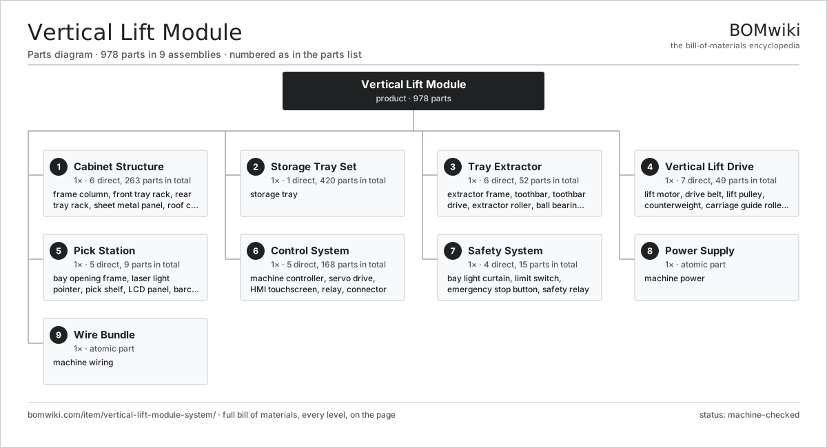
| # | Part | Qty | What it does |
|---|---|---|---|
| 1 | Cabinet Structure 6 parts | 1× | Bolted steel column enclosing the front and rear tray racks and the central lift shaft. |
| 2 | Storage Tray Set 1 parts | 1× | Steel trays that hold stored goods and ride between racks and the extractor. |
| 3 | Tray Extractor 6 parts | 1× | Shuttle on the lift carriage that pulls a tray from a rack and pushes it back into a slot. |
| 4 | Vertical Lift Drive 7 parts | 1× | Belt-and-counterweight hoist that raises the extractor carriage to any tray level or the pick window. |
| 5 | Pick Station 5 parts | 1× | Ergonomic delivery window with light pointer and bar enclosure where the operator picks from a presented tray. |
| 6 | Control System 5 parts | 1× | Machine controller, servo drives and HMI managing tray inventory and lift motions. |
| 7 | Safety System 4 parts | 1× | Bay light curtain, interlocks and emergency stop guarding the operator at the pick window. |
| 8 | Power Supply | 1× | machine power |
| 9 | Wire Bundle | 1× | machine wiring |
3D model
No 3D model yet. Have a CAD file of this? Add a 3D model — STL renders right on this page; STEP, FreeCAD, and OpenSCAD sources are welcome too (openly licensed, like all 3D models on BOMwiki).
Build & assembly graph
expand / collapse · shared sub-assemblies converge · links to related products · est. labourTap an assembly to expand/collapse · tap a part to open it · use “Open page” for any node · drag to pan, scroll to zoom.
Bill of materials for Vertical Lift Module
9 top-level lines · 88 rows shown · 978 parts total · indented to 3 levels| # | Item / sub-assembly | Part no. | Qty/assy | Ext. qty | Parts | Type |
|---|---|---|---|---|---|---|
| 1 | Cabinet Structure 6 parts | vertical-lift-module-system-cabinet | 1× | 1 | 263 | assembly |
| 1.1 | Frame Column | vertical-lift-module-system-frame-column | 4× | 4 | · | part |
| 1.2 | Front Tray Rack 2 parts | vertical-lift-module-system-front-rack | 1× | 1 | 120 | assembly |
| 1.2.1 | Rack Rail | vertical-lift-module-system-rack-rail | 40× | 40 | · | part |
| 1.2.2 | Tray Position Tab | vertical-lift-module-system-tray-position-tab | 80× | 80 | · | part |
| 1.3 | Rear Tray Rack 2 parts | vertical-lift-module-system-rear-rack | 1× | 1 | 120 | assembly |
| 1.3.1 | Rack Rail | vertical-lift-module-system-rack-rail | 40× | 40 | · | part |
| 1.3.2 | Tray Position Tab | vertical-lift-module-system-tray-position-tab | 80× | 80 | · | part |
| 1.4 | Sheet Metal Panel | sheet-panel | 12× | 12 | · | part |
| 1.5 | Roof Cap | vertical-lift-module-system-roof-cap | 1× | 1 | · | part |
| 1.6 | Fastener Set | fastener-set | 6× | 6 | · | part |
| 2 | Storage Tray Set 1 parts | vertical-lift-module-system-tray-set | 1× | 1 | 420 | assembly |
| 2.1 | Storage Tray 3 parts | vertical-lift-module-system-tray | 60× | 60 | 7 | assembly |
| 2.1.1 | Tray Pan | vertical-lift-module-system-tray-pan | 1× | 60 | · | part |
| 2.1.2 | Tray Edge Profile | vertical-lift-module-system-tray-edge-profile | 2× | 120 | · | part |
| 2.1.3 | Tray Divider | vertical-lift-module-system-tray-divider | 4× | 240 | · | part |
| 3 | Tray Extractor 6 parts | vertical-lift-module-system-extractor | 1× | 1 | 52 | assembly |
| 3.1 | Extractor Frame | vertical-lift-module-system-extractor-frame | 1× | 1 | · | part |
| 3.2 | Toothbar | vertical-lift-module-system-toothbar | 2× | 2 | · | part |
| 3.3 | Toothbar Drive 3 parts | vertical-lift-module-system-toothbar-drive | 1× | 1 | 29 | assembly |
| 3.3.1 | Geared Motor 6 parts + deeper › | vertical-lift-module-system-geared-motor | 1× | 1 | 27 | assembly |
| 3.3.2 | Drive Belt | drive-belt | 1× | 1 | · | part |
| 3.3.3 | Helical Gear Pair | gear-pair | 1× | 1 | · | part |
| 3.4 | Extractor Roller | vertical-lift-module-system-extractor-roller | 8× | 8 | · | part |
| 3.5 | Ball Bearing | ball-bearing | 8× | 8 | · | part |
| 3.6 | Tray Presence Sensor 2 parts | vertical-lift-module-system-tray-sensor | 2× | 2 | 2 | assembly |
| 3.6.1 | Bare PCB | pcb-bare | 1× | 2 | · | part |
| 3.6.2 | Connector | connector | 1× | 2 | · | part |
| 4 | Vertical Lift Drive 7 parts | vertical-lift-module-system-lift-drive | 1× | 1 | 49 | assembly |
| 4.1 | Lift Motor 8 parts | vertical-lift-module-system-lift-motor | 1× | 1 | 30 | assembly |
| 4.1.1 | Stator Assembly 3 parts + deeper › | stator-assembly | 1× | 1 | 3 | assembly |
| 4.1.2 | Rotor Assembly 4 parts + deeper › | rotor-assembly | 1× | 1 | 19 | assembly |
| 4.1.3 | Motor Housing | motor-housing | 1× | 1 | · | part |
| 4.1.4 | Ball Bearing | ball-bearing | 2× | 2 | · | part |
| 4.1.5 | Gearbox Housing | gearbox-housing | 1× | 1 | · | part |
| 4.1.6 | Helical Gear Pair | gear-pair | 2× | 2 | · | part |
| 4.1.7 | Holding Brake | vertical-lift-module-system-holding-brake | 1× | 1 | · | part |
| 4.1.8 | Encoder | encoder | 1× | 1 | · | part |
| 4.2 | Drive Belt | drive-belt | 2× | 2 | · | part |
| 4.3 | Lift Pulley | vertical-lift-module-system-lift-pulley | 2× | 2 | · | part |
| 4.4 | Counterweight | vertical-lift-module-system-counterweight | 2× | 2 | · | part |
| 4.5 | Carriage Guide Roller 2 parts | vertical-lift-module-system-carriage-guide | 4× | 4 | 2 | assembly |
| 4.5.1 | Guide Wheel | vertical-lift-module-system-guide-wheel | 1× | 4 | · | part |
| 4.5.2 | Ball Bearing | ball-bearing | 1× | 4 | · | part |
| 4.6 | Encoder | encoder | 1× | 1 | · | part |
| 4.7 | Ball Bearing | ball-bearing | 4× | 4 | · | part |
| 5 | Pick Station 5 parts | vertical-lift-module-system-pick-station | 1× | 1 | 9 | assembly |
| 5.1 | Bay Opening Frame | vertical-lift-module-system-bay-opening | 1× | 1 | · | part |
| 5.2 | Laser Light Pointer 3 parts | vertical-lift-module-system-light-pointer | 1× | 1 | 3 | assembly |
| 5.2.1 | Bare PCB | pcb-bare | 1× | 1 | · | part |
| 5.2.2 | Microcontroller | mcu | 1× | 1 | · | part |
| 5.2.3 | Laser Pointer Head | vertical-lift-module-system-laser-head | 1× | 1 | · | part |
| 5.3 | Pick Shelf | vertical-lift-module-system-pick-shelf | 1× | 1 | · | part |
| 5.4 | LCD Panel | lcd-panel | 1× | 1 | · | part |
| 5.5 | Barcode Scanner 3 parts | vertical-lift-module-system-barcode-scanner | 1× | 1 | 3 | assembly |
| 5.5.1 | Bare PCB | pcb-bare | 1× | 1 | · | part |
| 5.5.2 | Microcontroller | mcu | 1× | 1 | · | part |
| 5.5.3 | Connector | connector | 1× | 1 | · | part |
| 6 | Control System 5 parts | vertical-lift-module-system-control | 1× | 1 | 168 | assembly |
| 6.1 | Machine Controller 5 parts | vertical-lift-module-system-controller | 1× | 1 | 130 | assembly |
| 6.1.1 | Bare PCB | pcb-bare | 1× | 1 | · | part |
| 6.1.2 | Compute SoC Module | soc-module | 1× | 1 | · | part |
| 6.1.3 | Microcontroller | mcu | 2× | 2 | · | part |
| 6.1.4 | SMD Passive (R/C/L) | smd-passives | 120× | 120 | · | part |
| 6.1.5 | Connector | connector | 6× | 6 | · | part |
| 6.2 | Servo Drive 4 parts | vertical-lift-module-system-servo-drive | 2× | 2 | 10 | assembly |
| 6.2.1 | Bare PCB | pcb-bare | 1× | 2 | · | part |
| 6.2.2 | IGBT Power Module | igbt-module | 6× | 12 | · | part |
| 6.2.3 | Microcontroller | mcu | 1× | 2 | · | part |
| 6.2.4 | DC-Link Capacitor | dc-link-cap | 2× | 4 | · | part |
| 6.3 | HMI Touchscreen 4 parts | vertical-lift-module-system-hmi | 1× | 1 | 4 | assembly |
| 6.3.1 | LCD Panel | lcd-panel | 1× | 1 | · | part |
| 6.3.2 | Touch Digitizer | touch-digitizer | 1× | 1 | · | part |
| 6.3.3 | Bare PCB | pcb-bare | 1× | 1 | · | part |
| 6.3.4 | Microcontroller | mcu | 1× | 1 | · | part |
| 6.4 | Relay | relay | 6× | 6 | · | part |
| 6.5 | Connector | connector | 8× | 8 | · | part |
| 7 | Safety System 4 parts | vertical-lift-module-system-safety | 1× | 1 | 15 | assembly |
| 7.1 | Bay Light Curtain 2 parts | vertical-lift-module-system-light-curtain | 1× | 1 | 4 | assembly |
| 7.1.1 | Bare PCB | pcb-bare | 2× | 2 | · | part |
| 7.1.2 | Connector | connector | 2× | 2 | · | part |
| 7.2 | Limit Switch | limit-switch | 4× | 4 | · | part |
| 7.3 | Emergency Stop Button | vertical-lift-module-system-estop | 2× | 2 | · | part |
| 7.4 | Safety Relay 2 parts | vertical-lift-module-system-safety-relay | 1× | 1 | 5 | assembly |
| 7.4.1 | Bare PCB | pcb-bare | 1× | 1 | · | part |
| 7.4.2 | Relay | relay | 4× | 4 | · | part |
| 8 | Power Supply | power-supply | 1× | 1 | · | part |
| 9 | Wire Bundle | wire-bundle | 1× | 1 | · | part |
Related products
same domain, ranked by shared parts Reach Truck
832 parts · shares 10 with this page
Pallet Shuttle System
208 parts · shares 9 with this page
Reach Truck
832 parts · shares 10 with this page
Pallet Shuttle System
208 parts · shares 9 with this page
 Conveyor Sorter
2,957 parts · shares 7 with this page
Turret Truck
664 parts · shares 9 with this page
Conveyor Sorter
2,957 parts · shares 7 with this page
Turret Truck
664 parts · shares 9 with this page
 Bag Palletizer
951 parts · shares 9 with this page
Bag Palletizer
951 parts · shares 9 with this page
 Layer Palletizer
857 parts · shares 9 with this page
Layer Palletizer
857 parts · shares 9 with this page
Sourcing: possible vendors
Prices, MOQ, and lead times are algorithmic estimates, not quotes, and not claims about these companies. Company mappings are curated by keyword; est. price band $2k–$300k. How estimates work| Vendor | HQ | Specialty | MOQ | Lead time |
|---|---|---|---|---|
| toyota-industries.com ↗ | Kariya, JP | Forklifts & logistics | 20 units | 10–16 wks |
| kiongroup.com ↗ | Frankfurt, DE | Forklifts (Linde, STILL) | 20 units | 10–16 wks |
| jungheinrich.com ↗ | Hamburg, DE | Warehouse trucks | 20 units | 10–16 wks |
| crown.com ↗ | New Bremen, US | Forklifts | 20 units | 10–16 wks |
|
🇨🇳Hangcha
hcforklift.com ↗
|
Hangzhou, CN | Forklifts & material handling | 20 units | 10–16 wks |
1,234-word article