Rough-Terrain Forklift
ProductOverview
A rough-terrain forklift does the work of a warehouse forklift in places that have no warehouse floor. Construction sites, lumber yards, brickworks, and farms have soft, broken, sloping ground that would bog or tip a smooth-tired industrial truck, so this machine trades the small cushion tires for tall pneumatic tires, raises the whole body on a high-clearance frame, and drives all four wheels. The job is otherwise the same: pick a palletized load on a pair of forks, carry it, and place it, often several meters up. The machine is built around a Chassis Frame that carries a diesel Powertrain, a lifting Mast Assembly, the Hydraulic System that powers the lift, an Axle System on big tires, the Operator Cab, and the Electrical System.
Powertrain
Power comes from a Diesel Engine, typically a four-cylinder turbo diesel near 3.4 L producing about 55 kW. Diesel suits the duty because the engine spends much of its time at part load pushing through soft ground and driving the hydraulic pump, where its torque and fuel economy matter more than peak speed. The engine drives a Torque Converter, a fluid coupling that multiplies torque at low speed and lets the machine push into a pile or up a grade without stalling. Behind it, the Powershift Transmission uses hydraulically engaged Clutch Pack stacks to change between forward and reverse ranges under load, so the operator shuttles direction repeatedly during stacking without touching a manual clutch. A Transfer Case splits the drive and sends it through front and rear Driveshaft shafts to make the machine four-wheel drive, which is what keeps it moving when one axle loses grip.
Mast and lifting
The Mast Assembly is the visible front structure that raises the load. Two nested pairs of channel-section rails, the fixed Outer Mast Rail and the sliding Inner Mast Rail, telescope to roughly double the closed height. A hydraulic Lift Cylinder pushes the inner rail up, and a pair of Lift Chain chains run over sheaves so the Fork Carriage travels twice as far as the cylinder rod extends. The carriage rides on Mast Roller bearings against the rails to keep it square under an off-center load, and it carries two forged Fork Arm tines on the Carriage Plate. Two Tilt Cylinder rams tilt the whole mast forward to deposit a load and back to cradle it during travel over rough ground, which matters far more here than on a flat warehouse floor.
Hydraulics
The Hydraulic System is what does the lifting, tilting, and steering. An engine-driven Hydraulic Pump gear pump draws oil from the Hydraulic Reservoir and sends it to the Control Valve Bank bank, where sliding Valve Spool sections route flow to each cylinder as the operator moves the levers. A Relief Valve caps system pressure near 140 bar so a stalled cylinder or an overload cannot burst a line. Return oil passes through a Hydraulic Filter to keep grit out of the close-tolerance valves, and the high-pressure Hydraulic Hose runs carry oil out to the mast and axle. Steering is hydrostatic: turning the wheel meters oil to the rear Steer Cylinder rather than mechanically linking to the wheels.
Axles, wheels, and clearance
The defining feature is the Axle System. The front Drive Axle carries a Differential and a Final Drive planetary reduction in each hub, multiplying torque so the large wheels can claw through mud. The rear Steer Axle both steers and oscillates: it pivots on a center trunnion so all four wheels stay loaded when the machine crosses a rut, which keeps traction and stops the load from lurching. Tall Pneumatic Tire tires with deep lugs on steel Wheel Rim rims provide the grip and the ground clearance, and braking uses Wet Disc Brake oil-immersed discs sealed inside the axle so dust and water never reach the friction surfaces.
Cab, structure, and stability
The Operator Cab gives the operator a seated station with a suspension Operator Seat, a hydrostatic Steering Column, the hydraulic Control Levers, a Pedal Set, and an Instrument Cluster reporting engine and hydraulic status. The whole machine sits on the welded Main Frame, and a cast Counterweight at the rear balances the moment of a load held out on the forks: lifting capacity is set by how far that counterweight and the wheelbase can resist tipping forward. An Overhead Guard cage protects the operator from falling material. The Electrical System runs on 12 V, with a Battery, an Alternator, a Starter Motor, and Work Light lamps for low-light sites.
Variants and use
Capacities run from about 2,500 kg up to 4,500 kg at a 500 mm load center, with two-stage masts reaching 3 to 6 m. Some models add a side-shift carriage or a fork positioner to align loads without repositioning the truck, and many builders offer a free-lift mast that raises the forks without raising the closed mast height for work under low roofs. Operators are mostly outdoor contractors handling building materials, pipe, and bagged or palletized goods where a paved-surface forklift simply cannot go.
Rough-Terrain Forklift parts and their functions
7 top-level parts · 247 parts in total · full bill of materials below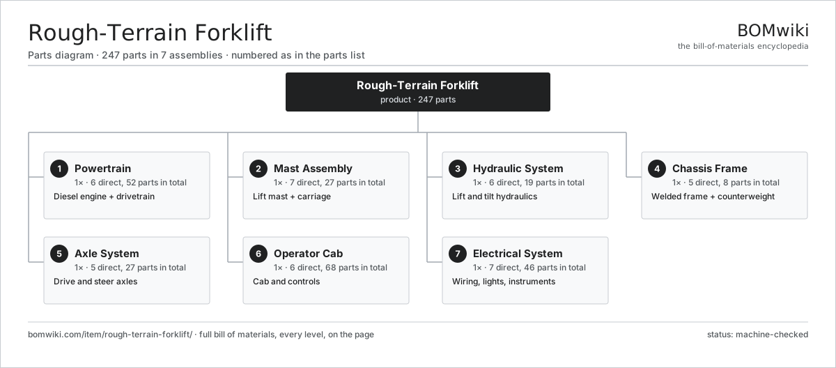
| # | Part | Qty | What it does |
|---|---|---|---|
| 1 | Powertrain 6 parts | 1× | Diesel engine + drivetrain |
| 2 | Mast Assembly 7 parts | 1× | Lift mast + carriage |
| 3 | Hydraulic System 6 parts | 1× | Lift and tilt hydraulics |
| 4 | Chassis Frame 5 parts | 1× | Welded frame + counterweight |
| 5 | Axle System 5 parts | 1× | Drive and steer axles |
| 6 | Operator Cab 6 parts | 1× | Cab and controls |
| 7 | Electrical System 7 parts | 1× | Wiring, lights, instruments |
3D model
No 3D model yet. Have a CAD file of this? Add a 3D model — STL renders right on this page; STEP, FreeCAD, and OpenSCAD sources are welcome too (openly licensed, like all 3D models on BOMwiki).
Build & assembly graph
expand / collapse · shared sub-assemblies converge · links to related products · est. labourTap an assembly to expand/collapse · tap a part to open it · use “Open page” for any node · drag to pan, scroll to zoom.
Bill of materials for Rough-Terrain Forklift
7 top-level lines · 85 rows shown · 247 parts total · indented to 3 levels| # | Item / sub-assembly | Part no. | Qty/assy | Ext. qty | Parts | Type |
|---|---|---|---|---|---|---|
| 1 | Powertrain 6 parts | rtf-powertrain | 1× | 1 | 52 | assembly |
| 1.1 | Diesel Engine 9 parts | rtf-diesel-engine | 1× | 1 | 31 | assembly |
| 1.1.1 | Cylinder Block | rtf-engine-block | 1× | 1 | · | part |
| 1.1.2 | Cylinder Head 3 parts + deeper › | rtf-cylinder-head | 1× | 1 | 17 | assembly |
| 1.1.3 | Piston Assembly | rtf-piston-set | 4× | 4 | · | part |
| 1.1.4 | Crankshaft | rtf-crankshaft | 1× | 1 | · | part |
| 1.1.5 | Turbocharger | rtf-turbocharger | 1× | 1 | · | part |
| 1.1.6 | Injection Pump | rtf-injection-pump | 1× | 1 | · | part |
| 1.1.7 | Engine Radiator | rtf-radiator | 1× | 1 | · | part |
| 1.1.8 | Oil Seal | oil-seal | 4× | 4 | · | part |
| 1.1.9 | Fastener Set | fastener-set | 1× | 1 | · | part |
| 1.2 | Torque Converter | rtf-torque-converter | 1× | 1 | · | part |
| 1.3 | Powershift Transmission 5 parts | rtf-powershift-transmission | 1× | 1 | 16 | assembly |
| 1.3.1 | Clutch Pack | rtf-clutch-pack | 3× | 3 | · | part |
| 1.3.2 | Helical Gear Pair | gear-pair | 3× | 3 | · | part |
| 1.3.3 | Gearbox Housing | gearbox-housing | 1× | 1 | · | part |
| 1.3.4 | Ball Bearing | ball-bearing | 6× | 6 | · | part |
| 1.3.5 | Oil Seal | oil-seal | 3× | 3 | · | part |
| 1.4 | Transfer Case | rtf-transfer-case | 1× | 1 | · | part |
| 1.5 | Driveshaft | rtf-driveshaft | 2× | 2 | · | part |
| 1.6 | Fuel Tank | rtf-fuel-tank | 1× | 1 | · | part |
| 2 | Mast Assembly 7 parts | rtf-mast-assembly | 1× | 1 | 27 | assembly |
| 2.1 | Outer Mast Rail | rtf-outer-mast-rail | 2× | 2 | · | part |
| 2.2 | Inner Mast Rail | rtf-inner-mast-rail | 2× | 2 | · | part |
| 2.3 | Lift Cylinder 4 parts | rtf-lift-cylinder | 1× | 1 | 4 | assembly |
| 2.3.1 | Cylinder Barrel | rtf-cylinder-barrel | 1× | 1 | · | part |
| 2.3.2 | Piston Rod | rtf-piston-rod | 1× | 1 | · | part |
| 2.3.3 | O-Ring Set | oring-set | 1× | 1 | · | part |
| 2.3.4 | Rod Seal | rtf-rod-seal | 1× | 1 | · | part |
| 2.4 | Lift Chain | rtf-lift-chain | 2× | 2 | · | part |
| 2.5 | Mast Roller | rtf-mast-roller | 8× | 8 | · | part |
| 2.6 | Fork Carriage 3 parts | rtf-fork-carriage | 1× | 1 | 7 | assembly |
| 2.6.1 | Carriage Plate | rtf-carriage-plate | 1× | 1 | · | part |
| 2.6.2 | Fork Arm | rtf-fork-arm | 2× | 2 | · | part |
| 2.6.3 | Mast Roller | rtf-mast-roller | 4× | 4 | · | part |
| 2.7 | Tilt Cylinder | rtf-tilt-cylinder | 2× | 2 | · | part |
| 3 | Hydraulic System 6 parts | rtf-hydraulic-system | 1× | 1 | 19 | assembly |
| 3.1 | Hydraulic Pump | rtf-hydraulic-pump | 1× | 1 | · | part |
| 3.2 | Control Valve Bank 3 parts | rtf-control-valve | 1× | 1 | 6 | assembly |
| 3.2.1 | Valve Spool | rtf-valve-spool | 4× | 4 | · | part |
| 3.2.2 | Relief Valve | rtf-relief-valve | 1× | 1 | · | part |
| 3.2.3 | O-Ring Set | oring-set | 1× | 1 | · | part |
| 3.3 | Hydraulic Reservoir | rtf-hydraulic-tank | 1× | 1 | · | part |
| 3.4 | Hydraulic Filter | rtf-hydraulic-filter | 1× | 1 | · | part |
| 3.5 | Hydraulic Hose | rtf-hydraulic-hose | 8× | 8 | · | part |
| 3.6 | Pressure Sensor | pressure-sensor | 2× | 2 | · | part |
| 4 | Chassis Frame 5 parts | rtf-chassis-frame | 1× | 1 | 8 | assembly |
| 4.1 | Main Frame | rtf-main-frame | 1× | 1 | · | part |
| 4.2 | Counterweight | rtf-counterweight | 1× | 1 | · | part |
| 4.3 | Overhead Guard | rtf-overhead-guard | 1× | 1 | · | part |
| 4.4 | Sheet Metal Panel | sheet-panel | 4× | 4 | · | part |
| 4.5 | Fastener Set | fastener-set | 1× | 1 | · | part |
| 5 | Axle System 5 parts | rtf-axle-system | 1× | 1 | 27 | assembly |
| 5.1 | Drive Axle 4 parts | rtf-drive-axle | 1× | 1 | 11 | assembly |
| 5.1.1 | Differential | rtf-differential | 1× | 1 | · | part |
| 5.1.2 | Final Drive | rtf-final-drive | 2× | 2 | · | part |
| 5.1.3 | Ball Bearing | ball-bearing | 4× | 4 | · | part |
| 5.1.4 | Oil Seal | oil-seal | 4× | 4 | · | part |
| 5.2 | Steer Axle 4 parts | rtf-steer-axle | 1× | 1 | 6 | assembly |
| 5.2.1 | Steering Knuckle | rtf-steer-knuckle | 2× | 2 | · | part |
| 5.2.2 | Steer Cylinder | rtf-steer-cylinder | 1× | 1 | · | part |
| 5.2.3 | Tie Rod | rtf-tie-rod | 1× | 1 | · | part |
| 5.2.4 | Ball Bearing | ball-bearing | 2× | 2 | · | part |
| 5.3 | Pneumatic Tire | rtf-tire-pneumatic | 4× | 4 | · | part |
| 5.4 | Wheel Rim | rtf-wheel-rim | 4× | 4 | · | part |
| 5.5 | Wet Disc Brake | rtf-wet-brake | 2× | 2 | · | part |
| 6 | Operator Cab 6 parts | rtf-operator-cab | 1× | 1 | 68 | assembly |
| 6.1 | Cab Frame | rtf-cab-frame | 1× | 1 | · | part |
| 6.2 | Operator Seat | rtf-operator-seat | 1× | 1 | · | part |
| 6.3 | Steering Column | rtf-steering-column | 1× | 1 | · | part |
| 6.4 | Control Levers | rtf-control-levers | 1× | 1 | · | part |
| 6.5 | Pedal Set | rtf-pedal-set | 1× | 1 | · | part |
| 6.6 | Instrument Cluster 4 parts | rtf-instrument-cluster | 1× | 1 | 63 | assembly |
| 6.6.1 | Bare PCB | pcb-bare | 1× | 1 | · | part |
| 6.6.2 | Microcontroller | mcu | 1× | 1 | · | part |
| 6.6.3 | LCD Panel | lcd-panel | 1× | 1 | · | part |
| 6.6.4 | SMD Passive (R/C/L) | smd-passives | 60× | 60 | · | part |
| 7 | Electrical System 7 parts | rtf-electrical-system | 1× | 1 | 46 | assembly |
| 7.1 | Battery | rtf-battery | 1× | 1 | · | part |
| 7.2 | Alternator | rtf-alternator | 1× | 1 | · | part |
| 7.3 | Starter Motor | rtf-starter-motor | 1× | 1 | · | part |
| 7.4 | Work Light | rtf-work-light | 4× | 4 | · | part |
| 7.5 | Wire Bundle | wire-bundle | 1× | 1 | · | part |
| 7.6 | Relay | relay | 8× | 8 | · | part |
| 7.7 | Connector | connector | 30× | 30 | · | part |
Related products
same domain, ranked by shared parts Telescopic Handler
380 parts · shares 37 with this page
Telescopic Handler
380 parts · shares 37 with this page
 Container Handler
552 parts · shares 30 with this page
Walkie Stacker
541 parts · shares 11 with this page
Order Picker
708 parts · shares 11 with this page
Container Handler
552 parts · shares 30 with this page
Walkie Stacker
541 parts · shares 11 with this page
Order Picker
708 parts · shares 11 with this page
 Articulated Forklift
2,417 parts · shares 6 with this page
Articulated Forklift
2,417 parts · shares 6 with this page
 Reach Truck
832 parts · shares 6 with this page
Reach Truck
832 parts · shares 6 with this page
Sourcing: possible vendors
Prices, MOQ, and lead times are algorithmic estimates, not quotes, and not claims about these companies. Company mappings are curated by keyword; est. price band $2k–$300k. How estimates work| Vendor | HQ | Specialty | MOQ | Lead time |
|---|---|---|---|---|
| toyota-industries.com ↗ | Kariya, JP | Forklifts & logistics | 20 units | 10–16 wks |
| kiongroup.com ↗ | Frankfurt, DE | Forklifts (Linde, STILL) | 20 units | 10–16 wks |
| jungheinrich.com ↗ | Hamburg, DE | Warehouse trucks | 20 units | 10–16 wks |
| crown.com ↗ | New Bremen, US | Forklifts | 20 units | 10–16 wks |
|
🇨🇳Hangcha
hcforklift.com ↗
|
Hangzhou, CN | Forklifts & material handling | 20 units | 10–16 wks |
909-word article