Counterbalance Forklift
ProductOverview
A counterbalance forklift is the most common lift truck in any warehouse, and its whole design follows from one principle: balance. When the forks pick up a load at the front of the truck, that weight tries to tip the truck forward over its front wheels. To stop that, the truck carries a heavy mass at the rear, so the front wheels act as a pivot with the load on one side and the counterweight on the other, like a seesaw. Getting that balance right at every lift height and reach is what the rest of the machine is built around, because the forks reach straight out from the front with no outriggers in the way, which is what lets the truck drive right up to a pallet.
The truck is built on a Chassis & Counterweight that carries the Counterweight. Mounted on it are the Mast Assembly that lifts, the Hydraulic System that powers the lift, the Powertrain that drives the truck, the Steering Axle, the Braking System, the Operator Station, and the Electrical System system that ties everything together.
Chassis and counterweight
The Chassis & Counterweight starts with a heavy welded Truck Frame that takes the concentrated loads from the mast and spreads them into the axles. At the rear sits the Counterweight, a large cast-iron block whose only job is to balance the load. On electric trucks the Battery Tray and battery double as part of this mass, which is why electric forklift batteries are so heavy. An Overhead Guard cage protects the operator from anything that might fall off a raised load. The front Drive Axle both drives and carries the bulk of the weight, riding on Forklift Tire units chosen for the floor: solid cushion tires for smooth indoor concrete, pneumatic tires for rough yards.
Mast and forks
The Mast Assembly is the lifting structure at the front. It is made of nested channels: a fixed Outer Mast Rail bolted to the truck and an Inner Mast Rail that telescopes up out of it. A Fork Carriage rides up these rails on Mast Roller bearings, and the two Fork Arm tines that go under the pallet hang from the carriage. Lifting is done by hydraulic cylinders working through Lift Chain leaf chains over sheaves, which multiplies a short cylinder stroke into a much longer carriage travel, so the truck can lift several meters with a compact cylinder. A Load Backrest keeps tall loads from tipping back toward the driver, and the whole mast can be tilted slightly to cradle the load or set it down level.
Hydraulics
The Hydraulic System is the muscle behind both lifting and steering. A Hydraulic Pump driven by the powertrain pressurizes oil from the Oil Reservoir, and the operator's levers move spools in a Control Valve Bank bank that directs that oil. To lift, oil flows to the Lift Cylinder units; to tilt the mast, it goes to the Tilt Cylinder units; to steer, it feeds the steering cylinder. A Relief Valve caps the pressure so an overload cannot burst anything, Hydraulic Hose lines carry the oil to each cylinder, and a Hydraulic Filter keeps the oil clean on its way back to the tank, since dirty oil is the main killer of hydraulic components.
Powertrain and steering
The Powertrain moves the truck. On an electric model, a Traction Motor draws from the Traction Battery through a Motor Controller and drives the front axle through a Transmission; engine-powered models swap the motor and battery for an engine and torque converter but keep the same layout. A Cooling Package package keeps the controller and powertrain from overheating during a hard shift.
The Steering Axle is at the rear, which is what gives a counterbalance truck its tight turning circle. A single Steering Cylinder swings the rear Steer Wheel units through a wide angle on their Steering Knuckle pivots, linked by Tie Rod arms. Steering from the rear lets the front of the truck, where the load is, swing into a pallet position while the tail pivots tightly, so the truck works in aisles only a little wider than its length plus the load.
Brakes, operator station, and electrical
The Braking System has to stop a truck that may weigh several tonnes with a load up high. A Master Cylinder driven by the Brake Pedal sends fluid to Wheel Brake drum brakes on the drive axle, and a Parking Brake holds the truck on grades. The Operator Station is built so one person can drive and lift at once: a suspended Operator Seat with a presence Seat Switch that cuts travel when nobody is sitting, a Steering Wheel, a row of Control Lever handles for lift and tilt, a Pedal Set, and a Instrument Display showing battery or fuel, hours, and warnings. A Seat Belt is critical, since the safest place in a tip-over is staying in the seat under the guard.
The Electrical System system links it all. A Vehicle Controller reads the operator inputs and the Sensor Set, which includes a Tilt Angle Sensor for mast tilt and a Speed Sensor that lets the truck slow itself when lifted high. A Wire Bundle harness, Work Light lamps, a Horn, and a Fuse & Relay Box complete the system. Variants run from compact three-wheel electric trucks for narrow indoor aisles to large pneumatic-tire diesel trucks that handle heavy loads outdoors, but the seesaw balance, the telescoping mast, and the rear-wheel steering are common to all of them.
Counterbalance Forklift parts and their functions
8 top-level parts · 612 parts in total · full bill of materials below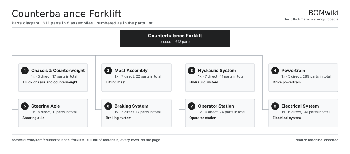
| # | Part | Qty | What it does |
|---|---|---|---|
| 1 | Chassis & Counterweight 5 parts | 1× | Truck chassis and counterweight |
| 2 | Mast Assembly 7 parts | 1× | Lifting mast |
| 3 | Hydraulic System 7 parts | 1× | Hydraulic system |
| 4 | Powertrain 5 parts | 1× | Drive powertrain |
| 5 | Steering Axle 5 parts | 1× | Steering axle |
| 6 | Braking System 5 parts | 1× | Braking system |
| 7 | Operator Station 6 parts | 1× | Operator station |
| 8 | Electrical System 6 parts | 1× | Electrical system |
3D model
No 3D model yet. Have a CAD file of this? Add a 3D model — STL renders right on this page; STEP, FreeCAD, and OpenSCAD sources are welcome too (openly licensed, like all 3D models on BOMwiki).
Build & assembly graph
expand / collapse · shared sub-assemblies converge · links to related products · est. labourTap an assembly to expand/collapse · tap a part to open it · use “Open page” for any node · drag to pan, scroll to zoom.
Bill of materials for Counterbalance Forklift
8 top-level lines · 121 rows shown · 612 parts total · indented to 3 levels| # | Item / sub-assembly | Part no. | Qty/assy | Ext. qty | Parts | Type |
|---|---|---|---|---|---|---|
| 1 | Chassis & Counterweight 5 parts | fork-chassis | 1× | 1 | 17 | assembly |
| 1.1 | Truck Frame | fork-frame | 1× | 1 | · | part |
| 1.2 | Counterweight | fork-counterweight | 1× | 1 | · | part |
| 1.3 | Overhead Guard | fork-overhead-guard | 1× | 1 | · | part |
| 1.4 | Drive Axle 5 parts | fork-drive-axle | 1× | 1 | 10 | assembly |
| 1.4.1 | Axle Housing | fork-axle-housing | 1× | 1 | · | part |
| 1.4.2 | Helical Gear Pair | gear-pair | 1× | 1 | · | part |
| 1.4.3 | Wheel Hub | fork-wheel-hub | 2× | 2 | · | part |
| 1.4.4 | Ball Bearing | ball-bearing | 4× | 4 | · | part |
| 1.4.5 | Oil Seal | oil-seal | 2× | 2 | · | part |
| 1.5 | Forklift Tire | fork-tire | 4× | 4 | · | part |
| 2 | Mast Assembly 7 parts | fork-mast-assembly | 1× | 1 | 22 | assembly |
| 2.1 | Inner Mast Rail | fork-inner-rail | 1× | 1 | · | part |
| 2.2 | Outer Mast Rail | fork-outer-rail | 1× | 1 | · | part |
| 2.3 | Fork Carriage 3 parts | fork-carriage | 1× | 1 | 7 | assembly |
| 2.3.1 | Carriage Plate | fork-carriage-plate | 1× | 1 | · | part |
| 2.3.2 | Carriage Hook | fork-carriage-hook | 2× | 2 | · | part |
| 2.3.3 | Mast Roller | fork-mast-roller | 4× | 4 | · | part |
| 2.4 | Mast Roller | fork-mast-roller | 8× | 8 | · | part |
| 2.5 | Lift Chain | fork-lift-chain | 2× | 2 | · | part |
| 2.6 | Fork Arm | fork-fork-arm | 2× | 2 | · | part |
| 2.7 | Load Backrest | fork-load-backrest | 1× | 1 | · | part |
| 3 | Hydraulic System 7 parts | fork-hydraulic-system | 1× | 1 | 41 | assembly |
| 3.1 | Hydraulic Pump 4 parts | fork-hydraulic-pump | 1× | 1 | 5 | assembly |
| 3.1.1 | Helical Gear Pair | gear-pair | 1× | 1 | · | part |
| 3.1.2 | Pump Housing | fork-pump-housing | 1× | 1 | · | part |
| 3.1.3 | Oil Seal | oil-seal | 2× | 2 | · | part |
| 3.1.4 | O-Ring Set | oring-set | 1× | 1 | · | part |
| 3.2 | Control Valve Bank 4 parts | fork-control-valve | 1× | 1 | 6 | assembly |
| 3.2.1 | Valve Body | fork-valve-body | 1× | 1 | · | part |
| 3.2.2 | Valve Spool | fork-valve-spool | 3× | 3 | · | part |
| 3.2.3 | Relief Valve | fork-relief-valve | 1× | 1 | · | part |
| 3.2.4 | O-Ring Set | oring-set | 1× | 1 | · | part |
| 3.3 | Lift Cylinder 4 parts | fork-lift-cylinder | 2× | 2 | 5 | assembly |
| 3.3.1 | Cylinder Tube | fork-cylinder-tube | 1× | 2 | · | part |
| 3.3.2 | Piston Rod | fork-piston-rod | 1× | 2 | · | part |
| 3.3.3 | O-Ring Set | oring-set | 2× | 4 | · | part |
| 3.3.4 | Oil Seal | oil-seal | 1× | 2 | · | part |
| 3.4 | Tilt Cylinder 4 parts | fork-tilt-cylinder | 2× | 2 | 5 | assembly |
| 3.4.1 | Cylinder Tube | fork-cylinder-tube | 1× | 2 | · | part |
| 3.4.2 | Piston Rod | fork-piston-rod | 1× | 2 | · | part |
| 3.4.3 | O-Ring Set | oring-set | 2× | 4 | · | part |
| 3.4.4 | Oil Seal | oil-seal | 1× | 2 | · | part |
| 3.5 | Oil Reservoir | fork-hydraulic-tank | 1× | 1 | · | part |
| 3.6 | Hydraulic Hose | fork-hydraulic-hose | 8× | 8 | · | part |
| 3.7 | Hydraulic Filter | fork-hydraulic-filter | 1× | 1 | · | part |
| 4 | Powertrain 5 parts | fork-powertrain | 1× | 1 | 289 | assembly |
| 4.1 | Traction Motor 5 parts | fork-traction-motor | 1× | 1 | 26 | assembly |
| 4.1.1 | Stator Assembly 3 parts + deeper › | stator-assembly | 1× | 1 | 3 | assembly |
| 4.1.2 | Rotor Assembly 4 parts + deeper › | rotor-assembly | 1× | 1 | 19 | assembly |
| 4.1.3 | Motor Housing | fork-motor-housing | 1× | 1 | · | part |
| 4.1.4 | Ball Bearing | ball-bearing | 2× | 2 | · | part |
| 4.1.5 | Motor Encoder | fork-motor-encoder | 1× | 1 | · | part |
| 4.2 | Transmission 4 parts | fork-transmission | 1× | 1 | 9 | assembly |
| 4.2.1 | Helical Gear Pair | gear-pair | 2× | 2 | · | part |
| 4.2.2 | Gearbox Housing | gearbox-housing | 1× | 1 | · | part |
| 4.2.3 | Ball Bearing | ball-bearing | 4× | 4 | · | part |
| 4.2.4 | Oil Seal | oil-seal | 2× | 2 | · | part |
| 4.3 | Motor Controller 4 parts | fork-motor-controller | 1× | 1 | 143 | assembly |
| 4.3.1 | Bare PCB | pcb-bare | 1× | 1 | · | part |
| 4.3.2 | Microcontroller | mcu | 1× | 1 | · | part |
| 4.3.3 | Power Module | fork-power-module | 1× | 1 | · | part |
| 4.3.4 | SMD Passive (R/C/L) | smd-passives | 140× | 140 | · | part |
| 4.4 | Traction Battery 3 parts | fork-battery-pack | 1× | 1 | 107 | assembly |
| 4.4.1 | Battery Cell | fork-battery-cell | 24× | 24 | · | part |
| 4.4.2 | Battery Management 3 parts + deeper › | fork-bms | 1× | 1 | 82 | assembly |
| 4.4.3 | Battery Tray | fork-battery-tray | 1× | 1 | · | part |
| 4.5 | Cooling Package 3 parts | fork-cooling | 1× | 1 | 4 | assembly |
| 4.5.1 | Radiator | fork-radiator | 1× | 1 | · | part |
| 4.5.2 | Cooling Fan | fork-cooling-fan | 1× | 1 | · | part |
| 4.5.3 | Coolant Hose | fork-coolant-hose | 2× | 2 | · | part |
| 5 | Steering Axle 5 parts | fork-steer-axle | 1× | 1 | 11 | assembly |
| 5.1 | Steer Axle Housing | fork-steer-housing | 1× | 1 | · | part |
| 5.2 | Steering Cylinder 3 parts | fork-steer-cylinder | 1× | 1 | 4 | assembly |
| 5.2.1 | Cylinder Tube | fork-cylinder-tube | 1× | 1 | · | part |
| 5.2.2 | Piston Rod | fork-piston-rod | 1× | 1 | · | part |
| 5.2.3 | O-Ring Set | oring-set | 2× | 2 | · | part |
| 5.3 | Steering Knuckle | fork-steer-knuckle | 2× | 2 | · | part |
| 5.4 | Steer Wheel | fork-steer-wheel | 2× | 2 | · | part |
| 5.5 | Tie Rod | fork-tie-rod | 2× | 2 | · | part |
| 6 | Braking System 5 parts | fork-brake-system | 1× | 1 | 17 | assembly |
| 6.1 | Master Cylinder 3 parts | fork-master-cylinder | 1× | 1 | 4 | assembly |
| 6.1.1 | Cylinder Tube | fork-cylinder-tube | 1× | 1 | · | part |
| 6.1.2 | Piston Rod | fork-piston-rod | 1× | 1 | · | part |
| 6.1.3 | O-Ring Set | oring-set | 2× | 2 | · | part |
| 6.2 | Wheel Brake 3 parts | fork-wheel-brake | 2× | 2 | 5 | assembly |
| 6.2.1 | Brake Drum | fork-brake-drum | 1× | 2 | · | part |
| 6.2.2 | Brake Shoe | fork-brake-shoe | 2× | 4 | · | part |
| 6.2.3 | Coil Spring | coil-spring | 2× | 4 | · | part |
| 6.3 | Parking Brake | fork-parking-brake | 1× | 1 | · | part |
| 6.4 | Brake Pedal | fork-brake-pedal | 1× | 1 | · | part |
| 6.5 | Brake Line Set | fork-brake-line | 1× | 1 | · | part |
| 7 | Operator Station 6 parts | fork-operator-station | 1× | 1 | 74 | assembly |
| 7.1 | Operator Seat 4 parts | fork-seat | 1× | 1 | 5 | assembly |
| 7.1.1 | Seat Frame | fork-seat-frame | 1× | 1 | · | part |
| 7.1.2 | Coil Spring | coil-spring | 2× | 2 | · | part |
| 7.1.3 | Seat Cushion | fork-seat-cushion | 1× | 1 | · | part |
| 7.1.4 | Seat Switch | fork-seat-switch | 1× | 1 | · | part |
| 7.2 | Steering Wheel | fork-steering-wheel | 1× | 1 | · | part |
| 7.3 | Control Lever | fork-control-lever | 3× | 3 | · | part |
| 7.4 | Pedal Set | fork-pedal-set | 1× | 1 | · | part |
| 7.5 | Instrument Display 4 parts | fork-display | 1× | 1 | 63 | assembly |
| 7.5.1 | Bare PCB | pcb-bare | 1× | 1 | · | part |
| 7.5.2 | Microcontroller | mcu | 1× | 1 | · | part |
| 7.5.3 | LCD Panel | lcd-panel | 1× | 1 | · | part |
| 7.5.4 | SMD Passive (R/C/L) | smd-passives | 60× | 60 | · | part |
| 7.6 | Seat Belt | fork-seatbelt | 1× | 1 | · | part |
| 8 | Electrical System 6 parts | fork-electrical | 1× | 1 | 141 | assembly |
| 8.1 | Vehicle Controller 4 parts | fork-vehicle-controller | 1× | 1 | 130 | assembly |
| 8.1.1 | Bare PCB | pcb-bare | 1× | 1 | · | part |
| 8.1.2 | Microcontroller | mcu | 1× | 1 | · | part |
| 8.1.3 | Relay | relay | 8× | 8 | · | part |
| 8.1.4 | SMD Passive (R/C/L) | smd-passives | 120× | 120 | · | part |
| 8.2 | Wire Bundle | wire-bundle | 1× | 1 | · | part |
| 8.3 | Work Light | fork-work-light | 4× | 4 | · | part |
| 8.4 | Horn | fork-horn | 1× | 1 | · | part |
| 8.5 | Sensor Set 3 parts | fork-sensor-set | 1× | 1 | 4 | assembly |
| 8.5.1 | Pressure Sensor | pressure-sensor | 2× | 2 | · | part |
| 8.5.2 | Tilt Angle Sensor | fork-angle-sensor | 1× | 1 | · | part |
| 8.5.3 | Speed Sensor | fork-speed-sensor | 1× | 1 | · | part |
| 8.6 | Fuse & Relay Box | fork-fuse-box | 1× | 1 | · | part |
Related products
same domain, ranked by shared parts Articulated Forklift
2,417 parts · shares 5 with this page
Articulated Forklift
2,417 parts · shares 5 with this page
 Container Handler
552 parts · shares 5 with this page
Open-Mouth Sack Filler
214 parts · shares 5 with this page
Container Handler
552 parts · shares 5 with this page
Open-Mouth Sack Filler
214 parts · shares 5 with this page
 Reach Truck
832 parts · shares 5 with this page
Reach Truck
832 parts · shares 5 with this page
 Rough-Terrain Forklift
247 parts · shares 5 with this page
Rough-Terrain Forklift
247 parts · shares 5 with this page
 Telescopic Handler
380 parts · shares 5 with this page
Telescopic Handler
380 parts · shares 5 with this page
Sourcing: possible vendors
Prices, MOQ, and lead times are algorithmic estimates, not quotes, and not claims about these companies. Company mappings are curated by keyword; est. price band $2k–$300k. How estimates work| Vendor | HQ | Specialty | MOQ | Lead time |
|---|---|---|---|---|
| toyota-industries.com ↗ | Kariya, JP | Forklifts & logistics | 20 units | 10–16 wks |
| kiongroup.com ↗ | Frankfurt, DE | Forklifts (Linde, STILL) | 20 units | 10–16 wks |
| jungheinrich.com ↗ | Hamburg, DE | Warehouse trucks | 20 units | 10–16 wks |
| crown.com ↗ | New Bremen, US | Forklifts | 20 units | 10–16 wks |
|
🇨🇳Hangcha
hcforklift.com ↗
|
Hangzhou, CN | Forklifts & material handling | 20 units | 10–16 wks |
970-word article