Vibrating Feeder
ProductOverview
A vibrating feeder meters bulk material out of a hopper at a controlled rate by shaking a steel tray. The tray vibrates with a directional linear motion that throws the material forward in a series of tiny hops, so the bed creeps toward the discharge while the feeder stays mechanically simple. By changing the vibration intensity the feed rate can be set anywhere from a trickle to full flow, which makes the vibrating feeder the standard way to draw ore, aggregate, coal, or granules from a bin and pass them to a crusher, screen, or downstream conveyor at a steady rate.
The feeder is built around a Vibrating Tray that carries the material, a Vibration Exciter that generates the vibration, a set of Isolation Springs that let the tray shake freely, and a Base Frame that supports it all. A Hopper Interface joins the moving tray to the static hopper, the Drive & Power spins the exciter, the Control Panel panel sets the rate, and Tray Liners protect the tray.
How it works
The motion is a directional linear vibration. The Vibration Exciter holds two Eccentric Shaft shafts that spin in opposite directions, kept in phase by Synchronizing Gear gears. The sideways components of their eccentric forces cancel and the in-line components add, leaving a single oscillating force along one axis tilted slightly above horizontal. The Vibrating Tray vibrates along that axis, so each cycle pitches the material up and forward, then drops away beneath it. The bed advances in small hops at a speed set by the amplitude and frequency, and because the tray surface is moving away from the grain during part of each cycle, abrasion is low compared with a dragged or scraped feeder.
The feed rate is tuned two ways. The Eccentric Weight settings change the amplitude mechanically, and the Variable-Frequency Drive varies the drive frequency electrically for fine real-time control.
Exciter and isolation
The Vibration Exciter is the engine of the feeder. Its Exciter Housing is an oil-filled casting carrying the eccentric shafts on Ball Bearing units sealed by Oil Seal rings against the oil bath and dust. The whole vibrating mass, tray plus exciter, is hung on Isolation Springs. The Coil Spring isolation springs let the tray oscillate at its working amplitude while Rubber Buffer buffers limit travel and damp shock. Without proper isolation the shaking force would pass into the supporting structure and shake the whole plant, so the springs are tuned so the operating frequency sits well above the natural frequency of the suspension.
Tray, liners, and wear
The Vibrating Tray is a stiff welded pan. A Tray Pan floor carries the material, Side Wall walls contain it, and Cross Stiffener ribs keep the pan from flexing under the cyclic load, which would crack it by fatigue. Because abrasive ore and aggregate wear the pan, bolt-in Tray Liners cover the working surfaces. A Floor Liner takes the sliding wear and a Side Liner protects the walls, both replaceable without scrapping the tray.
Hopper interface
The tray vibrates but the hopper above it does not, so the Hopper Interface bridges the gap. A Flexible Seal boot contains the material across the moving joint while passing no vibration into the bin. A Flow Gate at the hopper outlet sets the head of material on the tray, and adjustable Side Skirt skirts control the bed depth at the inlet so the feeder draws an even slice across its width rather than rat-holing.
Drive and control
The Drive & Power spins the exciter shafts through a Drive Belt V-belt from the Drive Motor, enclosed by a Belt Guard. The Control Panel panel sets the feed rate: the Variable-Frequency Drive varies the motor speed and therefore the vibration frequency, while the Controller Board carries an Microcontroller that runs the rate setpoint, interlocks the feeder with upstream and downstream equipment, and switches the Relay outputs. Tying feed rate to a downstream weigher lets the feeder hold a constant tonnage automatically.
Variants and use
Vibrating feeders are used to draw run-of-mine ore from a dump pocket to a primary crusher, to meter aggregate onto a screen, to feed coal to a boiler, and to dose granules and powders into a process. The linear twin-shaft exciter shown here gives high capacity and a tunable rate; lighter electromagnetic feeders use an oscillating armature instead of rotating eccentrics for fine dosing of small flows. Grizzly versions add bar spacing to the tray so the feeder scalps oversize while it feeds. The feeder is chosen over a belt or apron feeder when the duty calls for simple, low-maintenance metering of free-flowing or moderately sticky material, and the Control Panel makes it straightforward to integrate into an automated plant where the draw rate must track demand.
Vibrating Feeder parts and their functions
8 top-level parts · 176 parts in total · full bill of materials below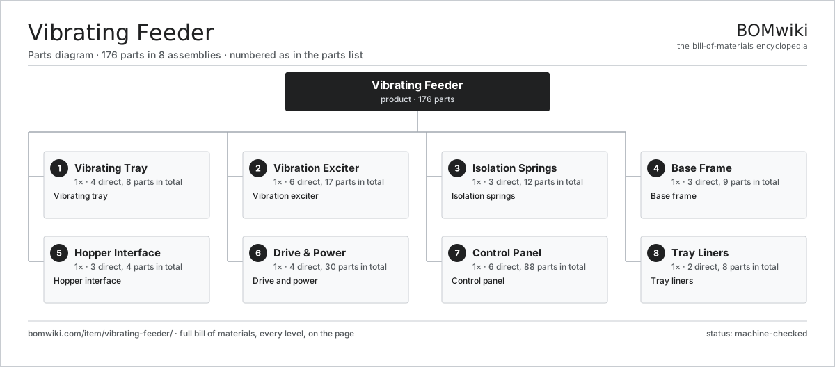
| # | Part | Qty | What it does |
|---|---|---|---|
| 1 | Vibrating Tray 4 parts | 1× | Vibrating tray |
| 2 | Vibration Exciter 6 parts | 1× | Vibration exciter |
| 3 | Isolation Springs 3 parts | 1× | Isolation springs |
| 4 | Base Frame 3 parts | 1× | Base frame |
| 5 | Hopper Interface 3 parts | 1× | Hopper interface |
| 6 | Drive & Power 4 parts | 1× | Drive and power |
| 7 | Control Panel 6 parts | 1× | Control panel |
| 8 | Tray Liners 2 parts | 1× | Tray liners |
3D model
No 3D model yet. Have a CAD file of this? Add a 3D model — STL renders right on this page; STEP, FreeCAD, and OpenSCAD sources are welcome too (openly licensed, like all 3D models on BOMwiki).
Build & assembly graph
expand / collapse · shared sub-assemblies converge · links to related products · est. labourTap an assembly to expand/collapse · tap a part to open it · use “Open page” for any node · drag to pan, scroll to zoom.
Bill of materials for Vibrating Feeder
8 top-level lines · 47 rows shown · 176 parts total · indented to 3 levels| # | Item / sub-assembly | Part no. | Qty/assy | Ext. qty | Parts | Type |
|---|---|---|---|---|---|---|
| 1 | Vibrating Tray 4 parts | vibrating-feeder-tray | 1× | 1 | 8 | assembly |
| 1.1 | Tray Pan | vibrating-feeder-tray-pan | 1× | 1 | · | part |
| 1.2 | Side Wall | vibrating-feeder-tray-side | 2× | 2 | · | part |
| 1.3 | Back Plate | vibrating-feeder-back-plate | 1× | 1 | · | part |
| 1.4 | Cross Stiffener | vibrating-feeder-stiffener | 4× | 4 | · | part |
| 2 | Vibration Exciter 6 parts | vibrating-feeder-exciter | 1× | 1 | 17 | assembly |
| 2.1 | Exciter Housing | vibrating-feeder-exciter-housing | 1× | 1 | · | part |
| 2.2 | Eccentric Shaft | vibrating-feeder-eccentric-shaft | 2× | 2 | · | part |
| 2.3 | Eccentric Weight | vibrating-feeder-eccentric-weight | 4× | 4 | · | part |
| 2.4 | Synchronizing Gear | vibrating-feeder-sync-gear | 2× | 2 | · | part |
| 2.5 | Ball Bearing | ball-bearing | 4× | 4 | · | part |
| 2.6 | Oil Seal | oil-seal | 4× | 4 | · | part |
| 3 | Isolation Springs 3 parts | vibrating-feeder-springs | 1× | 1 | 12 | assembly |
| 3.1 | Coil Spring | coil-spring | 4× | 4 | · | part |
| 3.2 | Spring Mount | vibrating-feeder-spring-mount | 4× | 4 | · | part |
| 3.3 | Rubber Buffer | vibrating-feeder-rubber-buffer | 4× | 4 | · | part |
| 4 | Base Frame 3 parts | vibrating-feeder-base | 1× | 1 | 9 | assembly |
| 4.1 | Base Weldment | vibrating-feeder-base-weldment | 1× | 1 | · | part |
| 4.2 | Anti-Vibration Mount | vibrating-feeder-anti-vibration-mount | 4× | 4 | · | part |
| 4.3 | Fastener Set | fastener-set | 4× | 4 | · | part |
| 5 | Hopper Interface 3 parts | vibrating-feeder-hopper-interface | 1× | 1 | 4 | assembly |
| 5.1 | Flexible Seal | vibrating-feeder-flexible-seal | 1× | 1 | · | part |
| 5.2 | Side Skirt | vibrating-feeder-skirt | 2× | 2 | · | part |
| 5.3 | Flow Gate | vibrating-feeder-flow-gate | 1× | 1 | · | part |
| 6 | Drive & Power 4 parts | vibrating-feeder-drive | 1× | 1 | 30 | assembly |
| 6.1 | Drive Motor 4 parts | vibrating-feeder-drive-motor | 1× | 1 | 25 | assembly |
| 6.1.1 | Stator Assembly 3 parts + deeper › | stator-assembly | 1× | 1 | 3 | assembly |
| 6.1.2 | Rotor Assembly 4 parts + deeper › | rotor-assembly | 1× | 1 | 19 | assembly |
| 6.1.3 | Ball Bearing | ball-bearing | 2× | 2 | · | part |
| 6.1.4 | Motor Frame | vibrating-feeder-motor-frame | 1× | 1 | · | part |
| 6.2 | Drive Belt | drive-belt | 2× | 2 | · | part |
| 6.3 | Drive Pulley | vibrating-feeder-pulley | 2× | 2 | · | part |
| 6.4 | Belt Guard | vibrating-feeder-belt-guard | 1× | 1 | · | part |
| 7 | Control Panel 6 parts | vibrating-feeder-control | 1× | 1 | 88 | assembly |
| 7.1 | Variable-Frequency Drive | vibrating-feeder-vfd | 1× | 1 | · | part |
| 7.2 | Controller Board 4 parts | vibrating-feeder-control-board | 1× | 1 | 76 | assembly |
| 7.2.1 | Bare PCB | pcb-bare | 1× | 1 | · | part |
| 7.2.2 | Microcontroller | mcu | 1× | 1 | · | part |
| 7.2.3 | SMD Passive (R/C/L) | smd-passives | 70× | 70 | · | part |
| 7.2.4 | Connector | connector | 4× | 4 | · | part |
| 7.3 | Power Supply | power-supply | 1× | 1 | · | part |
| 7.4 | Relay | relay | 3× | 3 | · | part |
| 7.5 | Wire Bundle | wire-bundle | 1× | 1 | · | part |
| 7.6 | Connector | connector | 6× | 6 | · | part |
| 8 | Tray Liners 2 parts | vibrating-feeder-liners | 1× | 1 | 8 | assembly |
| 8.1 | Floor Liner | vibrating-feeder-floor-liner | 4× | 4 | · | part |
| 8.2 | Side Liner | vibrating-feeder-side-liner | 4× | 4 | · | part |
Related products
same domain, ranked by shared parts Bag Palletizer
951 parts · shares 4 with this page
Pallet Shuttle System
208 parts · shares 4 with this page
Bag Palletizer
951 parts · shares 4 with this page
Pallet Shuttle System
208 parts · shares 4 with this page
 Sliding-Shoe Sorter
4,321 parts · shares 4 with this page
Sliding-Shoe Sorter
4,321 parts · shares 4 with this page
 Tilt-Tray Sorter
6,031 parts · shares 4 with this page
Tilt-Tray Sorter
6,031 parts · shares 4 with this page
 Vertical Spiral Conveyor
2,482 parts · shares 4 with this page
Narrow Belt Sorter
518 parts · shares 3 with this page
Vertical Spiral Conveyor
2,482 parts · shares 4 with this page
Narrow Belt Sorter
518 parts · shares 3 with this page
Sourcing: possible vendors
Prices, MOQ, and lead times are algorithmic estimates, not quotes, and not claims about these companies. Company mappings are curated by keyword; est. price band $2k–$300k. How estimates work| Vendor | HQ | Specialty | MOQ | Lead time |
|---|---|---|---|---|
| toyota-industries.com ↗ | Kariya, JP | Forklifts & logistics | 20 units | 10–16 wks |
| kiongroup.com ↗ | Frankfurt, DE | Forklifts (Linde, STILL) | 20 units | 10–16 wks |
| jungheinrich.com ↗ | Hamburg, DE | Warehouse trucks | 20 units | 10–16 wks |
| crown.com ↗ | New Bremen, US | Forklifts | 20 units | 10–16 wks |
|
🇨🇳Hangcha
hcforklift.com ↗
|
Hangzhou, CN | Forklifts & material handling | 20 units | 10–16 wks |
854-word article