Hay Bale Elevator
ProductOverview
The Hay Bale Elevator is an inclined open-truss conveyor that carries small square bales from ground level up into a hayloft, mow, or stack. It is one of the simplest powered material-handling machines on a farm: a long welded steel truss, two endless chains running up the slope, steel spike flights bridging the chains, and a small electric motor or tractor PTO turning the head shaft. A worker sets a bale onto the Feed Tray at the bottom, a passing flight catches it, and the bale rides the slope to the top where the Discharge Chute drops it off. The same machine is commonly used to move firewood, feed sacks, and boxes, anything light enough to be dragged up a steel pan by a moving flight.
Mechanically the elevator divides into seven subsystems: the Truss Frame that gives the machine its length and rigidity, the Feed Section where bales are loaded, the Chain & Flight System that does the conveying, the Head & Drive Section at the top, the Tail & Idler Section at the bottom, the Undercarriage that supports and moves the unit, and the Electrical Drive that powers it.
Frame and Slide Deck
The body is a lattice truss built from two formed channel chords, the Formed C-Channel Chord members, tied together by welded Truss Lattice Strut diagonals and additional Cross Brace members that keep the long span from twisting under load. The truss ships as a Lower Frame Section and an Upper Frame Section that bolt together at the Section End Plate flanges, with Splice Plate overlaps adding shear strength at the joint. A 32 ft machine simply adds more sections in the middle.
Bales do not ride on the chains directly. They drag against a steel deck made of several Slide Pan panels laid along the truss floor. A pair of Side Rail guides runs the full length to keep the bale centered between the two chains so a flight pushes it squarely rather than letting it skew and jam. The pan is usually galvanized so the bales slide with low friction and the surface resists rust through wet seasons.
Chain and Flight Conveying
The conveying action is the heart of the machine. Two endless strands, each a Drag Chain Strand, run up one side of the truss and back down the other in a continuous loop. Each strand is built from many Pintle Chain Link pintle links joined by a Chain Pin and cotter at every pitch. At regular intervals an Attachment Link replaces a plain link, giving a tab where a flight bolts on. A steel Spike Flight Bar bridges the two strands; this is a cross bar carrying welded spike teeth that bite into the bale and carry it up the slope. The flights are spaced 24 to 30 in apart, so on a typical incline two or three bales are climbing at once.
As the head shaft turns, both chains advance together and the flights sweep up the slide pan. A bale set on the feed tray is caught by the next flight, pressed onto the spikes by the Hold-Down Bar, and dragged the length of the deck. At chain speeds of 90 to 140 ft/min the machine clears 300 to 600 small bales per hour, fast enough to keep up with two or three people stacking at the top. On the return run the chains hang under the truss, guided and supported by UHMW Chain Guide Rail strips so the slack does not whip or wear against the steel. A Master Connecting Link lets the loop be opened for installation, shortening, or replacing a worn section without breaking individual pins.
Head Drive and Power
At the top, both chains wrap a Head Sprocket keyed to the Head Shaft, which spins in two Ball Bearing units carried in bolt-on Pillow Block Housing housings. The shaft is driven through a Reduction Gearbox that uses a Helical Gear Pair inside a cast Gearbox Housing, sealed by Oil Seal rings and filled with Gear Oil. The reducer drops the motor's speed by roughly thirty to one so the chains move at a safe conveying pace with high torque. Power reaches the reducer through a Drive Belt from the motor, and a Drive Sprocket couples the reducer output to the head shaft. A Belt Guard shields the belt and sprockets from clothing and stray hands.
The Electrical Drive is a Drive Motor of 1/2 to 1 hp built around a Stator Assembly and Rotor Assembly turning on two Ball Bearing units, with a Start Capacitor for starting torque and a Motor Pulley driving the belt. A Motor Mount hinges so the motor's own weight tensions the belt. The operator runs the machine from a Motor Switch, fed by a heavy Power Cord. Tractor-driven models replace the motor with a PTO shaft and right-angle drive.
Tail, Tension, and Undercarriage
At the bottom the chains wrap a Idler Sprocket pair on the Tail Shaft, again in Ball Bearing units and Pillow Block Housing housings. Chain tension is set by a Take-Up Adjuster at each side: a Take-Up Frame slot lets the tail bearing slide, an Adjuster Screw pulls it tight, and a Coil Spring cushions shock loads when a heavy bale snaps onto the flights. Correct take-up keeps the chains from skipping teeth on the sprockets.
The whole truss sits on a folding Support Leg pair, stiffened by a Leg Brace on each side. A Height Adjuster using an Adjuster Screw, a Crank Handle, and Lock Pin detents sets the incline anywhere from about 25 to 45 degrees, trading reach for steepness. For moving the elevator between barns, a Transport Wheel rides on a Axle Stub at each side so the folded unit can be towed. Held together by Fastener Set hardware throughout, the machine is meant to be assembled, adjusted, and serviced in the field with simple wrenches.
Hay Bale Elevator parts and their functions
7 top-level parts · 711 parts in total · full bill of materials below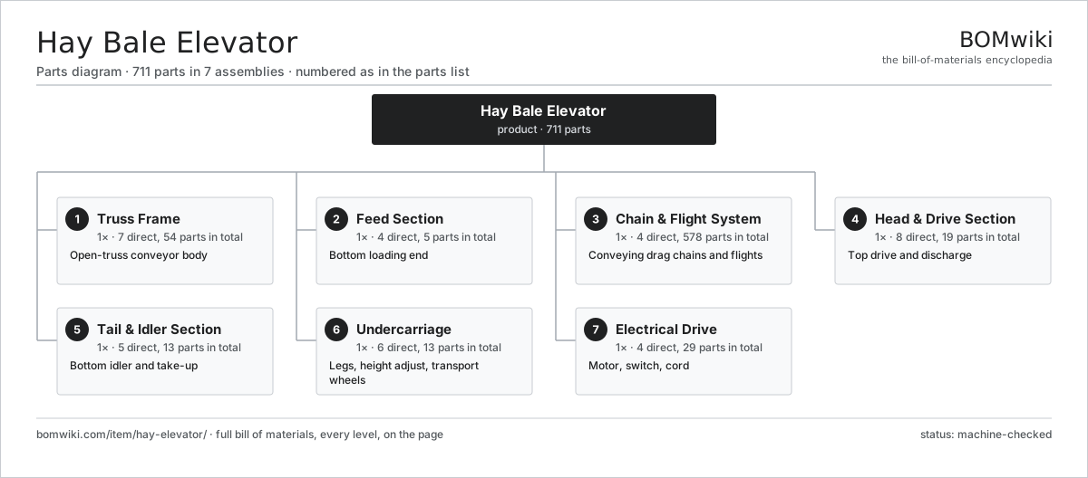
| # | Part | Qty | What it does |
|---|---|---|---|
| 1 | Truss Frame 7 parts | 1× | Open-truss conveyor body |
| 2 | Feed Section 4 parts | 1× | Bottom loading end |
| 3 | Chain & Flight System 4 parts | 1× | Conveying drag chains and flights |
| 4 | Head & Drive Section 8 parts | 1× | Top drive and discharge |
| 5 | Tail & Idler Section 5 parts | 1× | Bottom idler and take-up |
| 6 | Undercarriage 6 parts | 1× | Legs, height adjust, transport wheels |
| 7 | Electrical Drive 4 parts | 1× | Motor, switch, cord |
3D model
No 3D model yet. Have a CAD file of this? Add a 3D model — STL renders right on this page; STEP, FreeCAD, and OpenSCAD sources are welcome too (openly licensed, like all 3D models on BOMwiki).
Build & assembly graph
expand / collapse · shared sub-assemblies converge · links to related products · est. labourTap an assembly to expand/collapse · tap a part to open it · use “Open page” for any node · drag to pan, scroll to zoom.
Bill of materials for Hay Bale Elevator
7 top-level lines · 71 rows shown · 711 parts total · indented to 3 levels| # | Item / sub-assembly | Part no. | Qty/assy | Ext. qty | Parts | Type |
|---|---|---|---|---|---|---|
| 1 | Truss Frame 7 parts | hay-elevator-truss-frame | 1× | 1 | 54 | assembly |
| 1.1 | Lower Frame Section 3 parts | hay-elevator-lower-frame-section | 1× | 1 | 12 | assembly |
| 1.1.1 | Formed C-Channel Chord | hay-elevator-channel-chord | 2× | 2 | · | part |
| 1.1.2 | Truss Lattice Strut | hay-elevator-truss-strut | 8× | 8 | · | part |
| 1.1.3 | Section End Plate | hay-elevator-end-plate | 2× | 2 | · | part |
| 1.2 | Upper Frame Section 4 parts | hay-elevator-upper-frame-section | 1× | 1 | 13 | assembly |
| 1.2.1 | Formed C-Channel Chord | hay-elevator-channel-chord | 2× | 2 | · | part |
| 1.2.2 | Truss Lattice Strut | hay-elevator-truss-strut | 8× | 8 | · | part |
| 1.2.3 | Section End Plate | hay-elevator-end-plate | 2× | 2 | · | part |
| 1.2.4 | Discharge Chute | hay-elevator-discharge-chute | 1× | 1 | · | part |
| 1.3 | Side Rail | hay-elevator-side-rail | 2× | 2 | · | part |
| 1.4 | Cross Brace | hay-elevator-cross-brace | 14× | 14 | · | part |
| 1.5 | Slide Pan | hay-elevator-slide-pan | 4× | 4 | · | part |
| 1.6 | Splice Plate | hay-elevator-splice-plate | 8× | 8 | · | part |
| 1.7 | Fastener Set | fastener-set | 1× | 1 | · | part |
| 2 | Feed Section 4 parts | hay-elevator-feed-section | 1× | 1 | 5 | assembly |
| 2.1 | Feed Tray | hay-elevator-feed-tray | 1× | 1 | · | part |
| 2.2 | Feed Side Guide | hay-elevator-feed-guide | 2× | 2 | · | part |
| 2.3 | Hold-Down Bar | hay-elevator-hold-down-bar | 1× | 1 | · | part |
| 2.4 | Fastener Set | fastener-set | 1× | 1 | · | part |
| 3 | Chain & Flight System 4 parts | hay-elevator-chain-flight-system | 1× | 1 | 578 | assembly |
| 3.1 | Drag Chain Strand 3 parts | hay-elevator-drag-chain | 2× | 2 | 270 | assembly |
| 3.1.1 | Pintle Chain Link | hay-elevator-chain-link | 120× | 240 | · | part |
| 3.1.2 | Attachment Link | hay-elevator-attachment-link | 15× | 30 | · | part |
| 3.1.3 | Chain Pin | hay-elevator-chain-pin | 135× | 270 | · | part |
| 3.2 | Spike Flight Bar | hay-elevator-chain-flight | 30× | 30 | · | part |
| 3.3 | Master Connecting Link | hay-elevator-master-link | 4× | 4 | · | part |
| 3.4 | Chain Guide Rail | hay-elevator-chain-guide-rail | 4× | 4 | · | part |
| 4 | Head & Drive Section 8 parts | hay-elevator-head-drive-section | 1× | 1 | 19 | assembly |
| 4.1 | Head Shaft | hay-elevator-head-shaft | 1× | 1 | · | part |
| 4.2 | Head Sprocket | hay-elevator-head-sprocket | 2× | 2 | · | part |
| 4.3 | Ball Bearing | ball-bearing | 2× | 2 | · | part |
| 4.4 | Pillow Block Housing | hay-elevator-pillow-block | 2× | 2 | · | part |
| 4.5 | Reduction Gearbox 5 parts | hay-elevator-reduction-gearbox | 1× | 1 | 9 | assembly |
| 4.5.1 | Helical Gear Pair | gear-pair | 1× | 1 | · | part |
| 4.5.2 | Gearbox Housing | gearbox-housing | 1× | 1 | · | part |
| 4.5.3 | Ball Bearing | ball-bearing | 4× | 4 | · | part |
| 4.5.4 | Oil Seal | oil-seal | 2× | 2 | · | part |
| 4.5.5 | Gear Oil | hay-elevator-gear-oil | 1× | 1 | · | part |
| 4.6 | Drive Belt | drive-belt | 1× | 1 | · | part |
| 4.7 | Drive Sprocket | hay-elevator-drive-sprocket | 1× | 1 | · | part |
| 4.8 | Belt Guard | hay-elevator-belt-guard | 1× | 1 | · | part |
| 5 | Tail & Idler Section 5 parts | hay-elevator-tail-idler-section | 1× | 1 | 13 | assembly |
| 5.1 | Tail Shaft | hay-elevator-tail-shaft | 1× | 1 | · | part |
| 5.2 | Idler Sprocket | hay-elevator-idler-sprocket | 2× | 2 | · | part |
| 5.3 | Ball Bearing | ball-bearing | 2× | 2 | · | part |
| 5.4 | Pillow Block Housing | hay-elevator-pillow-block | 2× | 2 | · | part |
| 5.5 | Take-Up Adjuster 3 parts | hay-elevator-take-up-adjuster | 2× | 2 | 3 | assembly |
| 5.5.1 | Take-Up Frame | hay-elevator-take-up-frame | 1× | 2 | · | part |
| 5.5.2 | Adjuster Screw | hay-elevator-adjuster-screw | 1× | 2 | · | part |
| 5.5.3 | Coil Spring | coil-spring | 1× | 2 | · | part |
| 6 | Undercarriage 6 parts | hay-elevator-undercarriage | 1× | 1 | 13 | assembly |
| 6.1 | Support Leg | hay-elevator-support-leg | 2× | 2 | · | part |
| 6.2 | Leg Brace | hay-elevator-leg-brace | 2× | 2 | · | part |
| 6.3 | Height Adjuster 3 parts | hay-elevator-height-adjuster | 1× | 1 | 4 | assembly |
| 6.3.1 | Adjuster Screw | hay-elevator-adjuster-screw | 1× | 1 | · | part |
| 6.3.2 | Crank Handle | hay-elevator-crank-handle | 1× | 1 | · | part |
| 6.3.3 | Lock Pin | hay-elevator-lock-pin | 2× | 2 | · | part |
| 6.4 | Transport Wheel | hay-elevator-transport-wheel | 2× | 2 | · | part |
| 6.5 | Axle Stub | hay-elevator-axle-stub | 2× | 2 | · | part |
| 6.6 | Fastener Set | fastener-set | 1× | 1 | · | part |
| 7 | Electrical Drive 4 parts | hay-elevator-electrical-drive | 1× | 1 | 29 | assembly |
| 7.1 | Drive Motor 5 parts | hay-elevator-drive-motor | 1× | 1 | 26 | assembly |
| 7.1.1 | Stator Assembly 3 parts + deeper › | stator-assembly | 1× | 1 | 3 | assembly |
| 7.1.2 | Rotor Assembly 4 parts + deeper › | rotor-assembly | 1× | 1 | 19 | assembly |
| 7.1.3 | Ball Bearing | ball-bearing | 2× | 2 | · | part |
| 7.1.4 | Motor Pulley | hay-elevator-motor-pulley | 1× | 1 | · | part |
| 7.1.5 | Start Capacitor | hay-elevator-start-capacitor | 1× | 1 | · | part |
| 7.2 | Motor Switch | hay-elevator-motor-switch | 1× | 1 | · | part |
| 7.3 | Power Cord | hay-elevator-power-cord | 1× | 1 | · | part |
| 7.4 | Motor Mount | hay-elevator-motor-mount | 1× | 1 | · | part |
Related products
same domain, ranked by shared parts Bag Palletizer
951 parts · shares 2 with this page
Narrow Belt Sorter
518 parts · shares 2 with this page
Open-Mouth Sack Filler
214 parts · shares 2 with this page
Pallet Shuttle System
208 parts · shares 2 with this page
Pop-Up Wheel Sorter
705 parts · shares 2 with this page
Bag Palletizer
951 parts · shares 2 with this page
Narrow Belt Sorter
518 parts · shares 2 with this page
Open-Mouth Sack Filler
214 parts · shares 2 with this page
Pallet Shuttle System
208 parts · shares 2 with this page
Pop-Up Wheel Sorter
705 parts · shares 2 with this page
 Sliding-Shoe Sorter
4,321 parts · shares 2 with this page
Sliding-Shoe Sorter
4,321 parts · shares 2 with this page
Sourcing: possible vendors
Prices, MOQ, and lead times are algorithmic estimates, not quotes, and not claims about these companies. Company mappings are curated by keyword; est. price band $2k–$300k. How estimates work| Vendor | HQ | Specialty | MOQ | Lead time |
|---|---|---|---|---|
| toyota-industries.com ↗ | Kariya, JP | Forklifts & logistics | 20 units | 10–16 wks |
| kiongroup.com ↗ | Frankfurt, DE | Forklifts (Linde, STILL) | 20 units | 10–16 wks |
| jungheinrich.com ↗ | Hamburg, DE | Warehouse trucks | 20 units | 10–16 wks |
| crown.com ↗ | New Bremen, US | Forklifts | 20 units | 10–16 wks |
|
🇨🇳Hangcha
hcforklift.com ↗
|
Hangzhou, CN | Forklifts & material handling | 20 units | 10–16 wks |
1,089-word article