Mobile Gantry Lift
ProductOverview
A mobile gantry lift, often called a boat hoist or travel lift, is a self-propelled inverted-U frame that drives over a load, cradles it in slings, lifts it clear of the ground, and carries it elsewhere. The most common use is hauling boats out of the water at a marina: the machine straddles a slipway well, lowers two wide slings beneath the hull, lifts the boat, and drives it to a storage or repair area on the hard. The same configuration moves precast concrete, steel fabrications, and other long heavy items in yards where a fixed crane would be inflexible.
The geometry is what makes it useful. The Gantry Frame surrounds the load on three sides, so the lifting forces run straight down the legs into the wheels rather than overhanging like a jib crane. There is no counterweight and no outrigger setup; the machine simply drives into position, picks up, and goes. Capacities range from compact 15 tonne marina units up to 150 tonne yard machines.
Frame structure
The Gantry Frame is a welded steel portal. Two Top Beam members span the top and carry the hoist, four Gantry Leg members drop to the wheel corners, and Cross Tie braces near the bottom keep the legs square under load. The rear is closed by a removable Rear Span Gate so the machine can be backed over a boat in the slipway, then the gate refitted to brace the frame for travel. All the lifting load passes through this structure, so it is the most heavily engineered part of the machine.
Power and traction
The Power Unit is a turbo diesel Diesel Engine driving a Hydraulic Pump Pack that contains separate pumps for traction, hoisting, and steering. There is no mechanical driveline to the wheels. Instead each of the four Wheel Corner modules contains a hydraulic Wheel Drive Motor feeding a planetary Wheel Gearbox, so torque is delivered electrohydraulically and the speed is fully variable from a crawl. Hydrostatic drive suits the job because the machine spends most of its time inching precisely into and out of position rather than travelling fast.
Steering modes
Because every Wheel Corner sits on its own Steering Slew Ring and is turned by a Steering Cylinder, the wheels can point independently. The Steering System coordinates them through a Steering Controller that reads a Wheel Angle Encoder on each corner and commands the matching Steering Valve. Conventional mode steers like a vehicle; crab mode angles all four wheels the same way to move the whole frame sideways without rotating; and carousel mode points the wheels tangentially so the machine spins about its own center. This maneuverability lets a long boat be threaded into a tight storage row.
Hoisting the load
Lifting is done by the Hoist System. Two Hoist Winch units, each with a grooved Winch Drum and a spring-applied Winch Brake, reel wide Lifting Sling straps that pass under the hull. The winches hang from Hoist Trolley units that traverse along the top beams, so the operator can adjust the sling spacing fore and aft to balance the load and clear the keel and propeller. A Sling Load Cell on each sling reports the share of weight it carries, which both prevents overload and warns the operator if the load is hanging unevenly. Sheave blocks reeve the lines for the needed mechanical advantage.
Operator station and controls
The operator works from the Operator Station, an elevated cab mounted on one leg with a clear view down both sides of the frame. Control Joystick controls command traction, hoist, and steering, and a display shows sling loads, steering mode, and machine status. The whole machine runs on a CAN network managed by the Machine Controller with distributed I/O Module nodes reading Pressure Sensor and load feedback and driving the valves. Many marina units are operated by a single person who also walks the boat in by remote pendant during the final sling positioning.
Variants and use
Marina travel lifts dominate the smaller end, sized to the local fleet of sailboats and motor yachts, with frame widths chosen to clear the widest beam. Industrial gantry lifts at the larger end handle bridge segments, wind turbine components, and precast elements, sometimes paired so two machines lift one very long load in tandem. Electric battery versions are appearing for indoor and emissions-sensitive yards, replacing the diesel power unit with a battery pack and electric pump drive while keeping the same frame, wheel corners, and hoist arrangement.
Mobile Gantry Lift parts and their functions
7 top-level parts · 605 parts in total · full bill of materials below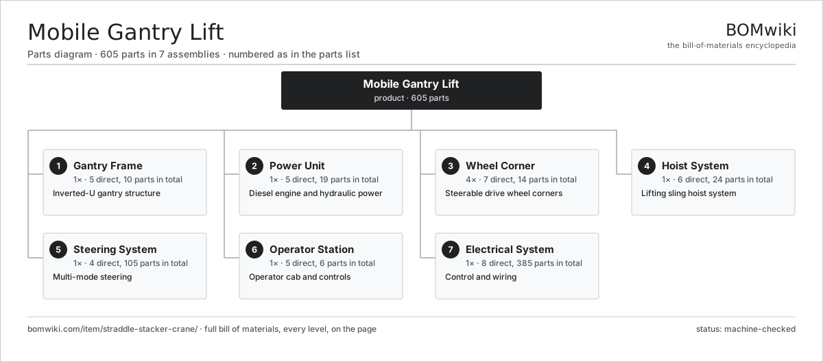
| # | Part | Qty | What it does |
|---|---|---|---|
| 1 | Gantry Frame 5 parts | 1× | Inverted-U gantry structure |
| 2 | Power Unit 5 parts | 1× | Diesel engine and hydraulic power |
| 3 | Wheel Corner 7 parts | 4× | Steerable drive wheel corners |
| 4 | Hoist System 6 parts | 1× | Lifting sling hoist system |
| 5 | Steering System 4 parts | 1× | Multi-mode steering |
| 6 | Operator Station 5 parts | 1× | Operator cab and controls |
| 7 | Electrical System 8 parts | 1× | Control and wiring |
3D model
No 3D model yet. Have a CAD file of this? Add a 3D model — STL renders right on this page; STEP, FreeCAD, and OpenSCAD sources are welcome too (openly licensed, like all 3D models on BOMwiki).
Build & assembly graph
expand / collapse · shared sub-assemblies converge · links to related products · est. labourTap an assembly to expand/collapse · tap a part to open it · use “Open page” for any node · drag to pan, scroll to zoom.
Bill of materials for Mobile Gantry Lift
7 top-level lines · 78 rows shown · 605 parts total · indented to 3 levels| # | Item / sub-assembly | Part no. | Qty/assy | Ext. qty | Parts | Type |
|---|---|---|---|---|---|---|
| 1 | Gantry Frame 5 parts | straddle-stacker-crane-gantry-frame | 1× | 1 | 10 | assembly |
| 1.1 | Top Beam | straddle-stacker-crane-top-beam | 2× | 2 | · | part |
| 1.2 | Gantry Leg | straddle-stacker-crane-leg | 4× | 4 | · | part |
| 1.3 | Cross Tie | straddle-stacker-crane-cross-tie | 2× | 2 | · | part |
| 1.4 | Rear Span Gate | straddle-stacker-crane-rear-gate | 1× | 1 | · | part |
| 1.5 | Fastener Set | fastener-set | 1× | 1 | · | part |
| 2 | Power Unit 5 parts | straddle-stacker-crane-power-unit | 1× | 1 | 19 | assembly |
| 2.1 | Diesel Engine 5 parts | straddle-stacker-crane-diesel-engine | 1× | 1 | 8 | assembly |
| 2.1.1 | Engine Block | straddle-stacker-crane-engine-block | 1× | 1 | · | part |
| 2.1.2 | Turbocharger | straddle-stacker-crane-turbo | 1× | 1 | · | part |
| 2.1.3 | Engine Radiator | straddle-stacker-crane-radiator | 1× | 1 | · | part |
| 2.1.4 | Ball Bearing | ball-bearing | 3× | 3 | · | part |
| 2.1.5 | Oil Seal | oil-seal | 2× | 2 | · | part |
| 2.2 | Hydraulic Pump Pack 5 parts | straddle-stacker-crane-pump-pack | 1× | 1 | 8 | assembly |
| 2.2.1 | Traction Pump | straddle-stacker-crane-traction-pump | 1× | 1 | · | part |
| 2.2.2 | Hoist Pump | straddle-stacker-crane-hoist-pump | 1× | 1 | · | part |
| 2.2.3 | Steering Pump | straddle-stacker-crane-steering-pump | 1× | 1 | · | part |
| 2.2.4 | Ball Bearing | ball-bearing | 2× | 2 | · | part |
| 2.2.5 | Oil Seal | oil-seal | 3× | 3 | · | part |
| 2.3 | Hydraulic Reservoir | straddle-stacker-crane-hyd-reservoir | 1× | 1 | · | part |
| 2.4 | Cooling Pack | straddle-stacker-crane-cooling-pack | 1× | 1 | · | part |
| 2.5 | Fuel Tank | straddle-stacker-crane-fuel-tank | 1× | 1 | · | part |
| 3 | Wheel Corner 7 parts | straddle-stacker-crane-wheel-corner | 4× | 4 | 14 | assembly |
| 3.1 | Wheel Drive Motor | straddle-stacker-crane-wheel-motor | 1× | 4 | · | part |
| 3.2 | Wheel Gearbox 4 parts | straddle-stacker-crane-wheel-gearbox | 1× | 4 | 5 | assembly |
| 3.2.1 | Helical Gear Pair | gear-pair | 1× | 4 | · | part |
| 3.2.2 | Gearbox Housing | gearbox-housing | 1× | 4 | · | part |
| 3.2.3 | Ball Bearing | ball-bearing | 2× | 8 | · | part |
| 3.2.4 | Oil Seal | oil-seal | 1× | 4 | · | part |
| 3.3 | Wheel and Tire | straddle-stacker-crane-solid-tire | 1× | 4 | · | part |
| 3.4 | Steering Slew Ring | straddle-stacker-crane-steer-ring | 1× | 4 | · | part |
| 3.5 | Steering Cylinder | straddle-stacker-crane-steer-cylinder | 1× | 4 | · | part |
| 3.6 | Ball Bearing | ball-bearing | 3× | 12 | · | part |
| 3.7 | Oil Seal | oil-seal | 2× | 8 | · | part |
| 4 | Hoist System 6 parts | straddle-stacker-crane-hoist-system | 1× | 1 | 24 | assembly |
| 4.1 | Hoist Winch 5 parts | straddle-stacker-crane-hoist-winch | 2× | 2 | 6 | assembly |
| 4.1.1 | Winch Drum | straddle-stacker-crane-winch-drum | 1× | 2 | · | part |
| 4.1.2 | Winch Motor | straddle-stacker-crane-winch-motor | 1× | 2 | · | part |
| 4.1.3 | Helical Gear Pair | gear-pair | 1× | 2 | · | part |
| 4.1.4 | Ball Bearing | ball-bearing | 2× | 4 | · | part |
| 4.1.5 | Winch Brake | straddle-stacker-crane-winch-brake | 1× | 2 | · | part |
| 4.2 | Hoist Trolley | straddle-stacker-crane-trolley | 2× | 2 | · | part |
| 4.3 | Lifting Sling | straddle-stacker-crane-lifting-sling | 2× | 2 | · | part |
| 4.4 | Sheave Block | straddle-stacker-crane-sheave-block | 4× | 4 | · | part |
| 4.5 | Sling Load Cell | straddle-stacker-crane-load-cell | 2× | 2 | · | part |
| 4.6 | Trolley Drive | straddle-stacker-crane-trolley-drive | 2× | 2 | · | part |
| 5 | Steering System 4 parts | straddle-stacker-crane-steering-system | 1× | 1 | 105 | assembly |
| 5.1 | Steering Controller 4 parts | straddle-stacker-crane-steer-controller | 1× | 1 | 96 | assembly |
| 5.1.1 | Bare PCB | pcb-bare | 1× | 1 | · | part |
| 5.1.2 | Microcontroller | mcu | 1× | 1 | · | part |
| 5.1.3 | SMD Passive (R/C/L) | smd-passives | 90× | 90 | · | part |
| 5.1.4 | Connector | connector | 4× | 4 | · | part |
| 5.2 | Steering Valve | straddle-stacker-crane-steer-valve | 4× | 4 | · | part |
| 5.3 | Wheel Angle Encoder | straddle-stacker-crane-steer-encoder | 4× | 4 | · | part |
| 5.4 | Steering Wheel | straddle-stacker-crane-steer-wheel | 1× | 1 | · | part |
| 6 | Operator Station 5 parts | straddle-stacker-crane-operator-station | 1× | 1 | 6 | assembly |
| 6.1 | Cab Shell | straddle-stacker-crane-cab-shell | 1× | 1 | · | part |
| 6.2 | Operator Seat | straddle-stacker-crane-operator-seat | 1× | 1 | · | part |
| 6.3 | Control Joystick | straddle-stacker-crane-joystick | 2× | 2 | · | part |
| 6.4 | LCD Panel | lcd-panel | 1× | 1 | · | part |
| 6.5 | Weather Canopy | straddle-stacker-crane-canopy | 1× | 1 | · | part |
| 7 | Electrical System 8 parts | straddle-stacker-crane-electrical-system | 1× | 1 | 385 | assembly |
| 7.1 | Machine Controller 4 parts | straddle-stacker-crane-main-controller | 1× | 1 | 167 | assembly |
| 7.1.1 | Bare PCB | pcb-bare | 1× | 1 | · | part |
| 7.1.2 | Microcontroller | mcu | 2× | 2 | · | part |
| 7.1.3 | SMD Passive (R/C/L) | smd-passives | 160× | 160 | · | part |
| 7.1.4 | Connector | connector | 4× | 4 | · | part |
| 7.2 | I/O Module 4 parts | straddle-stacker-crane-io-module | 2× | 2 | 86 | assembly |
| 7.2.1 | Bare PCB | pcb-bare | 1× | 2 | · | part |
| 7.2.2 | Microcontroller | mcu | 1× | 2 | · | part |
| 7.2.3 | Relay | relay | 4× | 8 | · | part |
| 7.2.4 | SMD Passive (R/C/L) | smd-passives | 80× | 160 | · | part |
| 7.3 | Wire Bundle | wire-bundle | 1× | 1 | · | part |
| 7.4 | Connector | connector | 24× | 24 | · | part |
| 7.5 | Relay | relay | 8× | 8 | · | part |
| 7.6 | Pressure Sensor | pressure-sensor | 4× | 4 | · | part |
| 7.7 | LED Work Light | straddle-stacker-crane-work-light | 8× | 8 | · | part |
| 7.8 | Starting Battery | straddle-stacker-crane-battery | 1× | 1 | · | part |
Related products
same domain, ranked by shared parts Articulated Forklift
2,417 parts · shares 3 with this page
Bulk Bag Discharger
178 parts · shares 3 with this page
Coal Yard Stacker
571 parts · shares 3 with this page
Articulated Forklift
2,417 parts · shares 3 with this page
Bulk Bag Discharger
178 parts · shares 3 with this page
Coal Yard Stacker
571 parts · shares 3 with this page
 Container Handler
552 parts · shares 3 with this page
Container Handler
552 parts · shares 3 with this page
 Counterbalance Forklift
612 parts · shares 3 with this page
Dense-Phase Conveying System
446 parts · shares 3 with this page
Counterbalance Forklift
612 parts · shares 3 with this page
Dense-Phase Conveying System
446 parts · shares 3 with this page
Sourcing: possible vendors
Prices, MOQ, and lead times are algorithmic estimates, not quotes, and not claims about these companies. Company mappings are curated by keyword; est. price band $2k–$300k. How estimates work| Vendor | HQ | Specialty | MOQ | Lead time |
|---|---|---|---|---|
| toyota-industries.com ↗ | Kariya, JP | Forklifts & logistics | 20 units | 10–16 wks |
| kiongroup.com ↗ | Frankfurt, DE | Forklifts (Linde, STILL) | 20 units | 10–16 wks |
| jungheinrich.com ↗ | Hamburg, DE | Warehouse trucks | 20 units | 10–16 wks |
| crown.com ↗ | New Bremen, US | Forklifts | 20 units | 10–16 wks |
|
🇨🇳Hangcha
hcforklift.com ↗
|
Hangzhou, CN | Forklifts & material handling | 20 units | 10–16 wks |
833-word article