Heavy Shoring Tower System
ProductOverview
A heavy shoring tower system is the temporary structure that carries a wet concrete slab, a bridge deck, or any other elevated load until that load can stand on its own. It is built from modular steel members that bolt and wedge together on site into a braced tower, then comes apart again for the next job. The system has to do two things at once: carry a large vertical load straight down to a firm bearing, and stay rigid against wind, out-of-plumb effects, and the sideways push of pouring concrete. The tower carries the load through its Vertical Standard standards, ties them together with the Horizontal Ledgers horizontals, and triangulates the whole frame with the Diagonal Bracing diagonals.
Load reaches the ground through a Adjustable Base Jack under each leg and reaches the formwork through a U-Head Screw Jack on top. The Primary Beam members sit in the head jacks and span the tower grid, the Secondary Joists and Deck assembly bears on the beams, and the Connection Node Hardware locks every joint. Before any pour the crew sets the tower with the Leveling and Plumb Kit so the deck is flat and every standard is vertical.
Standards and how load runs down
Each Vertical Standard is a galvanized Standard Tube of 48.3 mm outside diameter, the same section used across access scaffold so that couplers and ledgers interchange. The axial load runs down the tube wall and across the spigot joints, so the joints matter as much as the tube. A Spigot Sleeve welded into the tube top lets one standard stack on the next and keeps them coaxial, and a Spigot Pin locks the pair so the joint carries load rather than relying on friction. Welded to the tube at each 0.5 m lift is a Cup Node, a cup-and-collar fitting that takes four ledger ends in one wedge action. A Tube End Cap closes the tube against water so the galvanizing lasts through many hires. Leg capacity depends on the unbraced length between ledgers, which is why close ledger spacing lets a slender tube carry 60 to 90 kN per leg.
Ledgers, transoms, and bracing
A standard on its own is a strut that buckles. The Horizontal Ledgers turns the standards into a frame. Each Ledger Tube spans between two standards and ends in a forged Wedge Blade End that drops into a cup node and is locked by a wedge. Ledgers fix the bay width and, more importantly, they shorten the unbraced length of every standard so each leg can carry more. Where the deck load comes down, a heavier Load Transom carries the reaction back into the standards.
Ledgers hold the grid square but do not stop it leaning, so the Diagonal Bracing adds diagonals. A Face Brace runs across each vertical face and a Plan Brace lies in the horizontal plane at the base and at deck level. Plain Brace Tube lengths are fixed to the standards with a Brace Coupler, a swivel coupler whose forged Coupler Jaw halves close on the tube when the Tee Bolt is torqued to its rated slip resistance. Bracing is what lets the design carry the notional horizontal load that codes require on every falsework structure.
Base jacks and U-heads
The tower almost never lands on level ground, so a Adjustable Base Jack sits under each standard. Its Jack Spindle screws up and down to set the tower height, and the Adjusting Nut is turned to level the frame even with the full leg load already on it. At the foot a welded Base Plate spreads the point load onto a Sole Board, which in turn spreads it across the slab or ground so bearing pressure stays inside the safe value.
A U-Head Screw Jack does the same job at the top. Its Head Spindle drops into the standard and the Head Nut lifts the beam to the exact soffit level. A welded U-Fork Head cradles the primary beam so it cannot walk sideways, and a Locating Collar keeps the spindle centred so load runs true down the tube. Together the base and head jacks give 300 to 600 mm of adjustment at each end, which covers most uneven ground and slab falls.
Beams, joists, and the deck
The Primary Beam spans the tower grid sitting in the U-fork heads. Its Beam Section is an extruded AA6082-T6 aluminum I-section, light enough to lift by hand yet stiff enough to span several metres between towers. A Web Stiffener stiffener at each bearing point stops the slender web buckling over the fork, a Beam End Plate seats the beam squarely, and a Beam Clamp locks it so it cannot lift during a pour.
Across the primary beams the Secondary Joists and Deck assembly lays Secondary Joist members at 200 to 500 mm centres to suit the deck and the slab thickness. Each joist is held by a Joist Clip so it cannot roll. The Formwork Deck carries the cast soffit: phenolic-faced Formwork Plywood bears on the joists inside a Deck Frame, and an Edge Guard Board guards the platform edge.
Joints, leveling, and load checking
Every joint in the tower closes with the Connection Node Hardware. A Drive Wedge hammered through a blade end locks a ledger into a Rosette Node node, a Tie Coupler ties the tower back to a permanent structure to resist overturning, and a Locking Pin held by a Coil Spring secures the spigot and brace joints against accidental lift. The Leveling and Plumb Kit sets the tower before the pour: a Spirit Level flattens the beams, a Plumb Bob checks each standard runs vertical, and a Shim Set takes up the last few millimetres under the sole boards. On taller pours a Leg Load Monitor watches the leg load through pressure cells so the crew can see that no leg is running over its design value while the concrete goes down.
Heavy Shoring Tower System parts and their functions
9 top-level parts · 481 parts in total · full bill of materials below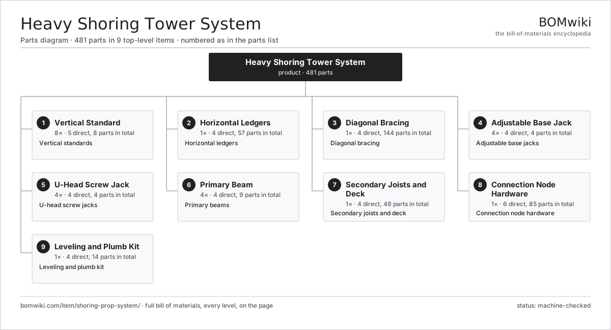
| # | Part | Qty | What it does |
|---|---|---|---|
| 1 | Vertical Standard 5 parts | 8× | Vertical standards |
| 2 | Horizontal Ledgers 4 parts | 1× | Horizontal ledgers |
| 3 | Diagonal Bracing 4 parts | 1× | Diagonal bracing |
| 4 | Adjustable Base Jack 4 parts | 4× | Adjustable base jacks |
| 5 | U-Head Screw Jack 4 parts | 4× | U-head screw jacks |
| 6 | Primary Beam 4 parts | 4× | Primary beams |
| 7 | Secondary Joists and Deck 4 parts | 1× | Secondary joists and deck |
| 8 | Connection Node Hardware 6 parts | 1× | Connection node hardware |
| 9 | Leveling and Plumb Kit 4 parts | 1× | Leveling and plumb kit |
3D model
No 3D model yet. Have a CAD file of this? Add a 3D model. STL renders right on this page; STEP, FreeCAD, and OpenSCAD sources are welcome too (openly licensed, like all 3D models on BOMwiki).
Build & assembly graph
expand / collapse · shared sub-assemblies converge · links to related products · est. labourTap an assembly to expand/collapse · tap a part to open it · use “Open page” for any node · drag to pan, scroll to zoom.
Bill of materials for Heavy Shoring Tower System
9 top-level lines · 60 rows shown · 481 parts total · indented to 3 levels| # | Item / sub-assembly | Part no. | Qty/assy | Ext. qty | Parts | Type |
|---|---|---|---|---|---|---|
| 1 | Vertical Standard 5 parts | shoring-prop-system-tower-leg | 8× | 8 | 8 | assembly |
| 1.1 | Standard Tube | shoring-prop-system-standard-tube | 1× | 8 | · | part |
| 1.2 | Cup Node | shoring-prop-system-cup-node | 4× | 32 | · | part |
| 1.3 | Spigot Pin | shoring-prop-system-spigot-pin | 1× | 8 | · | part |
| 1.4 | Spigot Sleeve | shoring-prop-system-spigot-sleeve | 1× | 8 | · | part |
| 1.5 | Tube End Cap | shoring-prop-system-end-cap | 1× | 8 | · | part |
| 2 | Horizontal Ledgers 4 parts | shoring-prop-system-ledger-set | 1× | 1 | 57 | assembly |
| 2.1 | Ledger Tube | shoring-prop-system-ledger-tube | 16× | 16 | · | part |
| 2.2 | Wedge Blade End | shoring-prop-system-ledger-blade | 32× | 32 | · | part |
| 2.3 | Load Transom | shoring-prop-system-transom | 8× | 8 | · | part |
| 2.4 | Fastener Set | fastener-set | 1× | 1 | · | part |
| 3 | Diagonal Bracing 4 parts | shoring-prop-system-brace-set | 1× | 1 | 144 | assembly |
| 3.1 | Face Brace | shoring-prop-system-face-brace | 8× | 8 | · | part |
| 3.2 | Plan Brace | shoring-prop-system-plan-brace | 4× | 4 | · | part |
| 3.3 | Brace Coupler 3 parts | shoring-prop-system-brace-coupler | 24× | 24 | 5 | assembly |
| 3.3.1 | Coupler Jaw | shoring-prop-system-coupler-jaw | 2× | 48 | · | part |
| 3.3.2 | Tee Bolt | shoring-prop-system-coupler-bolt | 2× | 48 | · | part |
| 3.3.3 | Fastener Set | fastener-set | 1× | 24 | · | part |
| 3.4 | Brace Tube | shoring-prop-system-brace-tube | 12× | 12 | · | part |
| 4 | Adjustable Base Jack 4 parts | shoring-prop-system-base-jack | 4× | 4 | 4 | assembly |
| 4.1 | Jack Spindle | shoring-prop-system-jack-spindle | 1× | 4 | · | part |
| 4.2 | Adjusting Nut | shoring-prop-system-jack-nut | 1× | 4 | · | part |
| 4.3 | Base Plate | shoring-prop-system-base-plate | 1× | 4 | · | part |
| 4.4 | Sole Board | shoring-prop-system-sole-board | 1× | 4 | · | part |
| 5 | U-Head Screw Jack 4 parts | shoring-prop-system-head-jack | 4× | 4 | 4 | assembly |
| 5.1 | Head Spindle | shoring-prop-system-head-spindle | 1× | 4 | · | part |
| 5.2 | Head Nut | shoring-prop-system-head-nut | 1× | 4 | · | part |
| 5.3 | U-Fork Head | shoring-prop-system-fork-head | 1× | 4 | · | part |
| 5.4 | Locating Collar | shoring-prop-system-head-collar | 1× | 4 | · | part |
| 6 | Primary Beam 4 parts | shoring-prop-system-primary-beam | 4× | 4 | 9 | assembly |
| 6.1 | Beam Section | shoring-prop-system-beam-section | 1× | 4 | · | part |
| 6.2 | Web Stiffener | shoring-prop-system-beam-web | 2× | 8 | · | part |
| 6.3 | Beam End Plate | shoring-prop-system-beam-endplate | 2× | 8 | · | part |
| 6.4 | Beam Clamp | shoring-prop-system-beam-clamp | 4× | 16 | · | part |
| 7 | Secondary Joists and Deck 4 parts | shoring-prop-system-secondary-joist | 1× | 1 | 49 | assembly |
| 7.1 | Secondary Joist | shoring-prop-system-joist | 12× | 12 | · | part |
| 7.2 | Formwork Deck 3 parts | shoring-prop-system-deck-panel | 1× | 1 | 9 | assembly |
| 7.2.1 | Formwork Plywood | shoring-prop-system-ply-sheet | 6× | 6 | · | part |
| 7.2.2 | Deck Frame | shoring-prop-system-deck-frame | 1× | 1 | · | part |
| 7.2.3 | Sheet Metal Panel | sheet-panel | 2× | 2 | · | part |
| 7.3 | Joist Clip | shoring-prop-system-joist-clip | 24× | 24 | · | part |
| 7.4 | Edge Guard Board | shoring-prop-system-edge-board | 4× | 4 | · | part |
| 8 | Connection Node Hardware 6 parts | shoring-prop-system-node-hardware | 1× | 1 | 85 | assembly |
| 8.1 | Drive Wedge | shoring-prop-system-wedge | 32× | 32 | · | part |
| 8.2 | Rosette Node | shoring-prop-system-rosette | 8× | 8 | · | part |
| 8.3 | Tie Coupler | shoring-prop-system-tie-coupler | 12× | 12 | · | part |
| 8.4 | Locking Pin | shoring-prop-system-locking-pin | 16× | 16 | · | part |
| 8.5 | Coil Spring | coil-spring | 16× | 16 | · | part |
| 8.6 | Fastener Set | fastener-set | 1× | 1 | · | part |
| 9 | Leveling and Plumb Kit 4 parts | shoring-prop-system-leveling-kit | 1× | 1 | 14 | assembly |
| 9.1 | Spirit Level | shoring-prop-system-spirit-level | 2× | 2 | · | part |
| 9.2 | Plumb Bob | shoring-prop-system-plumb-bob | 2× | 2 | · | part |
| 9.3 | Shim Set | shoring-prop-system-shim-set | 1× | 1 | · | part |
| 9.4 | Leg Load Monitor 6 parts | shoring-prop-system-load-monitor | 1× | 1 | 9 | assembly |
| 9.4.1 | Pressure Sensor | pressure-sensor | 4× | 4 | · | part |
| 9.4.2 | Bare PCB | pcb-bare | 1× | 1 | · | part |
| 9.4.3 | Microcontroller | mcu | 1× | 1 | · | part |
| 9.4.4 | LCD Panel | lcd-panel | 1× | 1 | · | part |
| 9.4.5 | Power Supply | power-supply | 1× | 1 | · | part |
| 9.4.6 | Wire Bundle | wire-bundle | 1× | 1 | · | part |
Related products
same domain, ranked by shared parts Hollowcore Slab Extruder
547 parts · shares 5 with this page
Hollowcore Slab Extruder
547 parts · shares 5 with this page
 Precast Concrete Mold
493 parts · shares 5 with this page
Precast Concrete Mold
493 parts · shares 5 with this page
 Clay Brick Extruder
154 parts · shares 5 with this page
Clay Brick Extruder
154 parts · shares 5 with this page
 Fiber Cement Sheet Machine
819 parts · shares 5 with this page
Roof Tile Press
443 parts · shares 5 with this page
Fiber Cement Sheet Machine
819 parts · shares 5 with this page
Roof Tile Press
443 parts · shares 5 with this page
 Smart Parcel Locker
278 parts · shares 5 with this page
Smart Parcel Locker
278 parts · shares 5 with this page
Sourcing: possible vendors
Browse the supplier directory → Prices, MOQ, and lead times are algorithmic estimates, not quotes, and not claims about these companies. Company mappings are curated by keyword; est. price band $50–$10k. How estimates work| Vendor | HQ | Specialty | MOQ | Lead time |
|---|---|---|---|---|
| assaabloy.com ↗ | Stockholm, SE | Locks & access | 1,000 units | 8–12 wks |
|
🇺🇸Allegion
allegion.com ↗
|
Dublin, US | Security products (Schlage) | 1,000 units | 8–12 wks |
| dormakaba.com ↗ | Rümlang, CH | Access & door systems | 1,000 units | 8–12 wks |
| honeywell.com ↗ | Charlotte, US | Building & safety tech | 1,000 units | 8–12 wks |
| hikvision.com ↗ | Hangzhou, CN | Surveillance & security | 1,000 units | 8–12 wks |
1,150-word article