Concrete Pipe Making Machine
ProductOverview
A concrete pipe making machine casts reinforced concrete drainage and sewer pipe from a stiff, almost dry mix that is compacted by heavy vibration rather than by pouring a wet slurry. Because the mix has near zero slump, the pipe holds its shape the moment the mould opens, so the machine can demould a green pipe right away and start the next cast on the same mould. That immediate stripping is what makes the process fast: a single mould turns out dozens of pipes per shift instead of one. The pipe wall ends up dense and strong because the vibration drives the aggregate into tight contact and expels trapped air before the cement has even begun to set.
The machine is built around a Machine Frame and Turntable that carries the mould under each work station, a Pipe Mould Set that shapes the pipe, a Vibration System system that compacts the concrete, a Concrete Feed System that meters concrete into the mould, a Cage Handling handler that places the reinforcement, a Hydraulic Power Unit unit that powers the moves, a Control System system that sequences the cycle, and a Stripping Head that lifts the finished pipe clear.
Forming the pipe wall
The pipe is shaped in the annular gap of the Pipe Mould Set. The outer wall comes from the Outer Jacket, a split steel jacket held shut by the Jacket Clamp Ring during the cast and swung open to release the pipe. The bore is set by the Inner Core. At the top a Socket Former shapes the bell, and at the base the Spigot Ring forms the spigot, so that one pipe seats into the next over a rubber ring. The cast pipe lifts away on a Mould Pallet that doubles as the spigot face. Mould steel is hard and ground smooth, since every blemish on the jacket prints onto thousands of pipes and any wear in the bell or spigot rings spoils the joint seal.
Compaction by vibration
Dry-cast concrete will not flow, so it has to be shaken into place. The Vibration System system carries several Eccentric Vibrator units, each an eccentric mass spun by a Vibrator Motor on a hardened Vibrator Shaft. The shafts run on sealed Ball Bearing sets protected by an Oil Seal at each end, because grout and dust would destroy an open bearing in days. The vibrators are coupled to the mould through a Isolation Mount of stiff rubber that passes the energy into the steel while sparing the frame and the bearings from the worst of the shock. Frequency matters: too low and the mix bridges and leaves voids, too high and the surface liquefies and the aggregate segregates. On a packerhead machine the compaction is done instead by a spinning Packer Head whose Compaction Roller units smear concrete outward against the jacket as the head climbs the bore on its Roller Drive Shaft.
Feeding and reinforcement
Concrete reaches the mould through the Concrete Feed System system. A batch drops into the Charging Skip, the Skip Hoist raises it to the top of the machine, and a rotating Distribution Head flings the mix evenly around the annulus through the Discharge Gate. Even distribution matters because a heavy side leaves a thin opposite wall. Before any concrete goes in, the Cage Handling handler uses a Cage Lifting Frame to lower a welded steel cage into the mould, where Centering Finger units hold it centered and Cover Spacer pieces set the concrete cover so the steel ends up buried at the right depth for corrosion protection and crush strength.
Hydraulics and control
The Hydraulic Power Unit unit supplies the muscle. Its Hydraulic Pump draws from the Oil Tank and feeds a Valve Block that routes oil to the Clamp Cylinder units that lock the jacket and the Lift Cylinder units that strip the pipe. An Accumulator stores pressure for the fast clamp moves and a full O-Ring Set keeps the system tight. Sequencing comes from the Control System cabinet, where a PLC reads several Pressure Sensor inputs and a Operator Panel lets the operator pick a pipe recipe. A Variable Frequency Drive ramps vibrator frequency, and a set of Motor Contactor units switches the larger motors.
Stripping and curing
When compaction finishes, the Stripping Head goes to work. The Stripping Head Plate withdraws the core while a powered Finishing Trowel smooths the bell, and the head rides true on a Strip Guide Bushing and a Linear Guide Rail pair. The green pipe rides off on its pallet to a curing area, where it gains most of its strength over the following days under cover or in a steam chamber. Because the mould is freed immediately, the limit on output is curing floor space and crane handling, not the machine itself.
Variants and use
Vibration machines suit large-diameter pipe and the heavy reinforcement that storm and sewer lines need, while packerhead machines are common for smaller diameters at high volume. Both make the standardized pipe that municipal drainage, culvert, and sewer networks rely on, where decades of buried service demand a dense wall, accurate joints, and consistent crush strength from one pipe to the next.
Concrete Pipe Making Machine parts and their functions
8 top-level parts · 154 parts in total · full bill of materials below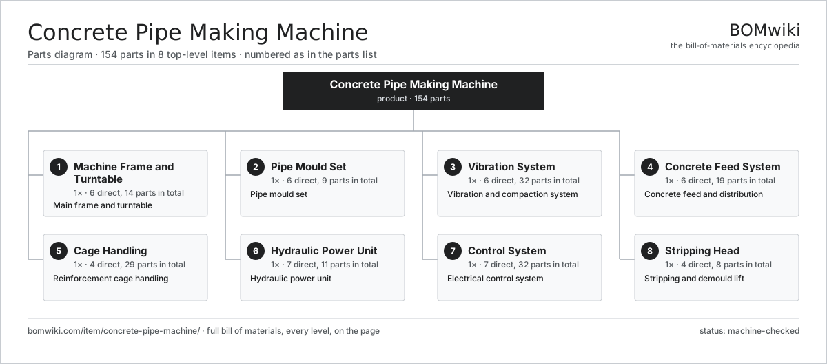
| # | Part | Qty | What it does |
|---|---|---|---|
| 1 | Machine Frame and Turntable 6 parts | 1× | Main frame and turntable |
| 2 | Pipe Mould Set 6 parts | 1× | Pipe mould set |
| 3 | Vibration System 6 parts | 1× | Vibration and compaction system |
| 4 | Concrete Feed System 6 parts | 1× | Concrete feed and distribution |
| 5 | Cage Handling 4 parts | 1× | Reinforcement cage handling |
| 6 | Hydraulic Power Unit 7 parts | 1× | Hydraulic power unit |
| 7 | Control System 7 parts | 1× | Electrical control system |
| 8 | Stripping Head 4 parts | 1× | Stripping and demould lift |
3D model
No 3D model yet. Have a CAD file of this? Add a 3D model. STL renders right on this page; STEP, FreeCAD, and OpenSCAD sources are welcome too (openly licensed, like all 3D models on BOMwiki).
Build & assembly graph
expand / collapse · shared sub-assemblies converge · links to related products · est. labourTap an assembly to expand/collapse · tap a part to open it · use “Open page” for any node · drag to pan, scroll to zoom.
Bill of materials for Concrete Pipe Making Machine
8 top-level lines · 67 rows shown · 154 parts total · indented to 3 levels| # | Item / sub-assembly | Part no. | Qty/assy | Ext. qty | Parts | Type |
|---|---|---|---|---|---|---|
| 1 | Machine Frame and Turntable 6 parts | concrete-pipe-machine-frame | 1× | 1 | 14 | assembly |
| 1.1 | Base Frame | concrete-pipe-machine-base-frame | 1× | 1 | · | part |
| 1.2 | Guide Column | concrete-pipe-machine-column | 4× | 4 | · | part |
| 1.3 | Indexing Turntable 3 parts | concrete-pipe-machine-turntable | 1× | 1 | 6 | assembly |
| 1.3.1 | Table Plate | concrete-pipe-machine-table-plate | 1× | 1 | · | part |
| 1.3.2 | Pallet Seat | concrete-pipe-machine-pallet-seat | 4× | 4 | · | part |
| 1.3.3 | Helical Gear Pair | gear-pair | 1× | 1 | · | part |
| 1.4 | Slew Bearing | concrete-pipe-machine-slew-bearing | 1× | 1 | · | part |
| 1.5 | Index Drive | concrete-pipe-machine-index-drive | 1× | 1 | · | part |
| 1.6 | Fastener Set | fastener-set | 1× | 1 | · | part |
| 2 | Pipe Mould Set 6 parts | concrete-pipe-machine-mould | 1× | 1 | 9 | assembly |
| 2.1 | Outer Jacket | concrete-pipe-machine-outer-jacket | 1× | 1 | · | part |
| 2.2 | Inner Core | concrete-pipe-machine-core | 1× | 1 | · | part |
| 2.3 | Socket Former | concrete-pipe-machine-socket-former | 1× | 1 | · | part |
| 2.4 | Spigot Ring | concrete-pipe-machine-spigot-ring | 1× | 1 | · | part |
| 2.5 | Mould Pallet | concrete-pipe-machine-pallet | 4× | 4 | · | part |
| 2.6 | Jacket Clamp Ring | concrete-pipe-machine-clamp | 1× | 1 | · | part |
| 3 | Vibration System 6 parts | concrete-pipe-machine-vibration | 1× | 1 | 32 | assembly |
| 3.1 | Eccentric Vibrator | concrete-pipe-machine-vibrator | 4× | 4 | · | part |
| 3.2 | Vibrator Shaft | concrete-pipe-machine-vib-shaft | 4× | 4 | · | part |
| 3.3 | Isolation Mount | concrete-pipe-machine-vib-mount | 4× | 4 | · | part |
| 3.4 | Vibrator Motor | concrete-pipe-machine-vib-motor | 4× | 4 | · | part |
| 3.5 | Ball Bearing | ball-bearing | 8× | 8 | · | part |
| 3.6 | Oil Seal | oil-seal | 8× | 8 | · | part |
| 4 | Concrete Feed System 6 parts | concrete-pipe-machine-feed | 1× | 1 | 19 | assembly |
| 4.1 | Charging Skip | concrete-pipe-machine-skip | 1× | 1 | · | part |
| 4.2 | Skip Hoist | concrete-pipe-machine-skip-hoist | 1× | 1 | · | part |
| 4.3 | Distribution Head | concrete-pipe-machine-distributor | 1× | 1 | · | part |
| 4.4 | Packer Head 3 parts | concrete-pipe-machine-packer-head | 1× | 1 | 13 | assembly |
| 4.4.1 | Compaction Roller | concrete-pipe-machine-roller | 6× | 6 | · | part |
| 4.4.2 | Roller Drive Shaft | concrete-pipe-machine-roller-shaft | 1× | 1 | · | part |
| 4.4.3 | Ball Bearing | ball-bearing | 6× | 6 | · | part |
| 4.5 | Discharge Gate | concrete-pipe-machine-feed-gate | 1× | 1 | · | part |
| 4.6 | Drive Belt | drive-belt | 2× | 2 | · | part |
| 5 | Cage Handling 4 parts | concrete-pipe-machine-cage | 1× | 1 | 29 | assembly |
| 5.1 | Cage Lifting Frame | concrete-pipe-machine-cage-lifter | 1× | 1 | · | part |
| 5.2 | Centering Finger | concrete-pipe-machine-cage-finger | 8× | 8 | · | part |
| 5.3 | Cover Spacer | concrete-pipe-machine-spacer-block | 12× | 12 | · | part |
| 5.4 | Coil Spring | coil-spring | 8× | 8 | · | part |
| 6 | Hydraulic Power Unit 7 parts | concrete-pipe-machine-hydraulic | 1× | 1 | 11 | assembly |
| 6.1 | Oil Tank | concrete-pipe-machine-hpu-tank | 1× | 1 | · | part |
| 6.2 | Hydraulic Pump | concrete-pipe-machine-hpu-pump | 1× | 1 | · | part |
| 6.3 | Valve Block | concrete-pipe-machine-valve-block | 1× | 1 | · | part |
| 6.4 | Lift Cylinder | concrete-pipe-machine-lift-cylinder | 2× | 2 | · | part |
| 6.5 | Clamp Cylinder | concrete-pipe-machine-clamp-cylinder | 4× | 4 | · | part |
| 6.6 | Accumulator | concrete-pipe-machine-accumulator | 1× | 1 | · | part |
| 6.7 | O-Ring Set | oring-set | 1× | 1 | · | part |
| 7 | Control System 7 parts | concrete-pipe-machine-control | 1× | 1 | 32 | assembly |
| 7.1 | PLC 4 parts | concrete-pipe-machine-plc | 1× | 1 | 8 | assembly |
| 7.1.1 | Microcontroller | mcu | 1× | 1 | · | part |
| 7.1.2 | Bare PCB | pcb-bare | 2× | 2 | · | part |
| 7.1.3 | SMD Passive (R/C/L) | smd-passives | 1× | 1 | · | part |
| 7.1.4 | Relay | relay | 4× | 4 | · | part |
| 7.2 | Operator Panel 3 parts | concrete-pipe-machine-hmi | 1× | 1 | 4 | assembly |
| 7.2.1 | LCD Panel | lcd-panel | 1× | 1 | · | part |
| 7.2.2 | Bare PCB | pcb-bare | 1× | 1 | · | part |
| 7.2.3 | Connector | connector | 2× | 2 | · | part |
| 7.3 | Motor Contactor | concrete-pipe-machine-contactor | 6× | 6 | · | part |
| 7.4 | Variable Frequency Drive | concrete-pipe-machine-vfd | 2× | 2 | · | part |
| 7.5 | Pressure Sensor | pressure-sensor | 3× | 3 | · | part |
| 7.6 | Wire Bundle | wire-bundle | 1× | 1 | · | part |
| 7.7 | Connector | connector | 8× | 8 | · | part |
| 8 | Stripping Head 4 parts | concrete-pipe-machine-stripper | 1× | 1 | 8 | assembly |
| 8.1 | Stripping Head Plate | concrete-pipe-machine-strip-head | 1× | 1 | · | part |
| 8.2 | Finishing Trowel | concrete-pipe-machine-trowel | 1× | 1 | · | part |
| 8.3 | Strip Guide Bushing | concrete-pipe-machine-strip-guide | 4× | 4 | · | part |
| 8.4 | Linear Guide Rail | linear-guide | 2× | 2 | · | part |
Related products
same domain, ranked by shared parts Clay Brick Extruder
154 parts · shares 11 with this page
Clay Brick Extruder
154 parts · shares 11 with this page
 Fiber Cement Sheet Machine
819 parts · shares 11 with this page
Fiber Cement Sheet Machine
819 parts · shares 11 with this page
 Paving Block Machine
154 parts · shares 11 with this page
Paving Block Machine
154 parts · shares 11 with this page
 AAC Block Plant
155 parts · shares 10 with this page
AAC Block Plant
155 parts · shares 10 with this page
 Gypsum Board Production Line
207 parts · shares 10 with this page
Insulated Sandwich Panel Line
1,856 parts · shares 10 with this page
Gypsum Board Production Line
207 parts · shares 10 with this page
Insulated Sandwich Panel Line
1,856 parts · shares 10 with this page
Sourcing: possible vendors
Browse the supplier directory → Prices, MOQ, and lead times are algorithmic estimates, not quotes, and not claims about these companies. Company mappings are curated by keyword; est. price band $50–$10k. How estimates work| Vendor | HQ | Specialty | MOQ | Lead time |
|---|---|---|---|---|
| assaabloy.com ↗ | Stockholm, SE | Locks & access | 1,000 units | 8–12 wks |
|
🇺🇸Allegion
allegion.com ↗
|
Dublin, US | Security products (Schlage) | 1,000 units | 8–12 wks |
| dormakaba.com ↗ | Rümlang, CH | Access & door systems | 1,000 units | 8–12 wks |
| honeywell.com ↗ | Charlotte, US | Building & safety tech | 1,000 units | 8–12 wks |
| hikvision.com ↗ | Hangzhou, CN | Surveillance & security | 1,000 units | 8–12 wks |
968-word article