Tunnel Form System
ProductOverview
A tunnel form casts the two walls and the floor slab of a room in a single concrete pour, which is why it is the standard method for repetitive cellular buildings such as hotels, student blocks, prisons, and apartment towers where the same room shape repeats hundreds of times. The form is shaped like an upside-down U. Two L-shaped Half-Shell units are set facing each other and bolted together along the ceiling line at the Crown Joint, so each half supplies one wall and half the soffit. Reinforcement and any services are fixed, the concrete is poured in one go, and the next morning the form is struck, rolled out, and flown up to repeat the same cell one floor higher.
The appeal is speed and finish. Casting walls and slab together gives a monolithic structure with no cold joint between them, and the steel face leaves an off-form surface smooth enough to paint with no plaster. A site running enough forms can turn a floor every few days, which is far faster than building walls and slab as separate operations. The cost is heavy plant: each form weighs several tonnes, needs a tower crane to move it, and only pays off when the same cell repeats often enough to spread that cost.
The half-shells
Each Half-Shell is an L. The upright leg is a Wall Panel and the foot is a Soffit Panel, joined by a Corner Gusset that holds the angle square under load. The face that touches the concrete is a Sheet Metal Panel skin, 4 to 6 mm steel plate welded up flat. Behind the wall skin run vertical Face Stiffener channels and horizontal Waling sections that carry the full liquid pressure of the fresh pour without the face bowing. Where two facing walls must be held to each other, a Tie Socket socket takes a through-tie. The soffit skin is carried on deep Soffit Bearer beams, and a set of Camber Shim pieces pre-cambers the soffit so the slab casts flat once it deflects under its own wet weight. Stiffness without dead weight comes from the Rib Truss units behind the panels, each a light lattice of Truss Chord and Truss Diagonal members bolted at Node Plate joints.
Closing and tying the form
The two half-shells meet at the cell ceiling. The Crown Flange along each soffit edge is pulled together with Crown Bolt fasteners, a Alignment Cone guides the halves into exact register, and a Crown Seal strip stops grout leaking down the ceiling line. The open ends of the tunnel are closed by the Stop Ends assembly: an End Panel at each end held by End Clamp clamps, with a Door Box and a Window Box set into the wall to leave the door and window openings. An Edge Seal strip closes the joint against the previous day's pour so the new wall keys cleanly to the one below.
Holding it plumb and level
Before the pour the form must sit dead level and dead plumb, because every wall it casts inherits its alignment. The Prop System carries the soffit load to the floor through telescopic Prop Jack units, each built on a Ball Screw running in a Prop Tube, driven by a Jack Nut and held at height by a Jack Collar. The props are triangulated with Brace Tube diagonals and stand on spread Prop Foot plates, and a Plumb Screw tilts each wall a fraction to bring it true. At the base the Levelling System system sets the form down: a Levelling Jack under each corner, again a Ball Screw and Level Nut on a Base Shoe, raises the soffit to the set level, while Alignment Bolt push bolts and a Laser Target read against a site laser to set the line.
Striking and moving
The form has to release a cell it has just cast without damaging the green concrete, so it strikes inward. Short Kicker Jack units at the foot of each wall, each a Ball Screw driving a Kicker Shoe against the slab with Coil Spring return, push the panels a few millimetres off the cured wall to break the bond. Then the Striking Gear takes over: a Servo Motor turns the Striking Screw pair through the Striking Drive drive, lowering the soffit in a controlled drop, while the Drop Linkage and its Retract Arm arms draw the wall feet inward so the whole form folds clear. Once free, the form rides out on the Rolling Chassis. A Chassis Jack lifts it onto its Wheel Set units, each a steel Wheel on a Axle turning on Ball Bearing supports, and a Track Guide keeps it running straight to the slab edge.
Flying and pouring
At the slab edge the Lifting Frame takes the load. A Strongback spreads the lift across the form so it does not distort, a Balance Beam keeps the Sling Set slings vertical, and rated Lifting Eye points let the crane fly the form up to the next floor in one piece. Through the pour and stripping the crew works off the Working Platform, a cantilever Platform Deck on Cantilever Arm brackets with Handrail guards, Toe Board kickplates, and an Access Ladder. The whole loop, set, level, pour, cure, strike, roll, and fly, runs on a 24-hour cycle, so one form casts one cell a day and a crew with several forms turns a full floor in a working week.
Tunnel Form System parts and their functions
9 top-level parts · 559 parts in total · full bill of materials below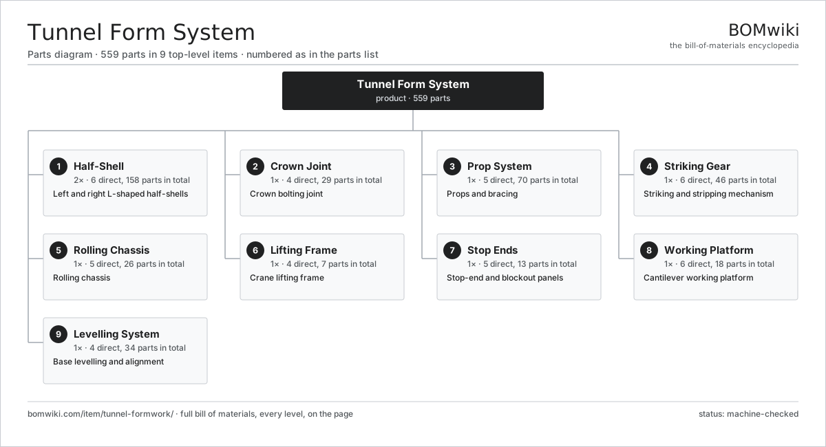
| # | Part | Qty | What it does |
|---|---|---|---|
| 1 | Half-Shell 6 parts | 2× | Left and right L-shaped half-shells |
| 2 | Crown Joint 4 parts | 1× | Crown bolting joint |
| 3 | Prop System 5 parts | 1× | Props and bracing |
| 4 | Striking Gear 6 parts | 1× | Striking and stripping mechanism |
| 5 | Rolling Chassis 5 parts | 1× | Rolling chassis |
| 6 | Lifting Frame 4 parts | 1× | Crane lifting frame |
| 7 | Stop Ends 5 parts | 1× | Stop-end and blockout panels |
| 8 | Working Platform 6 parts | 1× | Cantilever working platform |
| 9 | Levelling System 4 parts | 1× | Base levelling and alignment |
3D model
No 3D model yet. Have a CAD file of this? Add a 3D model. STL renders right on this page; STEP, FreeCAD, and OpenSCAD sources are welcome too (openly licensed, like all 3D models on BOMwiki).
Build & assembly graph
expand / collapse · shared sub-assemblies converge · links to related products · est. labourTap an assembly to expand/collapse · tap a part to open it · use “Open page” for any node · drag to pan, scroll to zoom.
Bill of materials for Tunnel Form System
9 top-level lines · 88 rows shown · 559 parts total · indented to 3 levels| # | Item / sub-assembly | Part no. | Qty/assy | Ext. qty | Parts | Type |
|---|---|---|---|---|---|---|
| 1 | Half-Shell 6 parts | tunnel-formwork-half-shell | 2× | 2 | 158 | assembly |
| 1.1 | Wall Panel 5 parts | tunnel-formwork-wall-panel | 1× | 2 | 27 | assembly |
| 1.1.1 | Sheet Metal Panel | sheet-panel | 6× | 12 | · | part |
| 1.1.2 | Face Stiffener | tunnel-formwork-stiffener | 10× | 20 | · | part |
| 1.1.3 | Waling | tunnel-formwork-waling | 4× | 8 | · | part |
| 1.1.4 | Tie Socket | tunnel-formwork-tie-point | 6× | 12 | · | part |
| 1.1.5 | Fastener Set | fastener-set | 1× | 2 | · | part |
| 1.2 | Soffit Panel 4 parts | tunnel-formwork-soffit-panel | 1× | 2 | 20 | assembly |
| 1.2.1 | Sheet Metal Panel | sheet-panel | 5× | 10 | · | part |
| 1.2.2 | Soffit Bearer | tunnel-formwork-soffit-bearer | 6× | 12 | · | part |
| 1.2.3 | Camber Shim | tunnel-formwork-camber-shim | 8× | 16 | · | part |
| 1.2.4 | Fastener Set | fastener-set | 1× | 2 | · | part |
| 1.3 | Corner Gusset | tunnel-formwork-corner-gusset | 1× | 2 | · | part |
| 1.4 | Rib Truss 4 parts | tunnel-formwork-rib-truss | 8× | 16 | 13 | assembly |
| 1.4.1 | Truss Chord | tunnel-formwork-truss-chord | 2× | 32 | · | part |
| 1.4.2 | Truss Diagonal | tunnel-formwork-truss-diagonal | 6× | 96 | · | part |
| 1.4.3 | Node Plate | tunnel-formwork-node-plate | 4× | 64 | · | part |
| 1.4.4 | Fastener Set | fastener-set | 1× | 16 | · | part |
| 1.5 | Edge Rail | tunnel-formwork-edge-rail | 4× | 8 | · | part |
| 1.6 | Fastener Set | fastener-set | 2× | 4 | · | part |
| 2 | Crown Joint 4 parts | tunnel-formwork-crown-joint | 1× | 1 | 29 | assembly |
| 2.1 | Crown Flange | tunnel-formwork-crown-flange | 4× | 4 | · | part |
| 2.2 | Crown Bolt | tunnel-formwork-crown-bolt | 16× | 16 | · | part |
| 2.3 | Crown Seal | tunnel-formwork-crown-seal | 1× | 1 | · | part |
| 2.4 | Alignment Cone | tunnel-formwork-align-cone | 8× | 8 | · | part |
| 3 | Prop System 5 parts | tunnel-formwork-prop-system | 1× | 1 | 70 | assembly |
| 3.1 | Prop Jack 5 parts | tunnel-formwork-prop-jack | 6× | 6 | 6 | assembly |
| 3.1.1 | Ball Screw | ball-screw | 1× | 6 | · | part |
| 3.1.2 | Prop Tube | tunnel-formwork-prop-tube | 1× | 6 | · | part |
| 3.1.3 | Jack Nut | tunnel-formwork-jack-nut | 1× | 6 | · | part |
| 3.1.4 | Jack Collar | tunnel-formwork-jack-collar | 1× | 6 | · | part |
| 3.1.5 | Ball Bearing | ball-bearing | 2× | 12 | · | part |
| 3.2 | Kicker Jack 3 parts | tunnel-formwork-kicker-jack | 4× | 4 | 4 | assembly |
| 3.2.1 | Ball Screw | ball-screw | 1× | 4 | · | part |
| 3.2.2 | Kicker Shoe | tunnel-formwork-kicker-shoe | 1× | 4 | · | part |
| 3.2.3 | Coil Spring | coil-spring | 2× | 8 | · | part |
| 3.3 | Brace Tube | tunnel-formwork-brace-tube | 8× | 8 | · | part |
| 3.4 | Prop Foot | tunnel-formwork-prop-foot | 6× | 6 | · | part |
| 3.5 | Plumb Screw | tunnel-formwork-plumb-screw | 4× | 4 | · | part |
| 4 | Striking Gear 6 parts | tunnel-formwork-striking-gear | 1× | 1 | 46 | assembly |
| 4.1 | Striking Screw | tunnel-formwork-strike-screw | 2× | 2 | · | part |
| 4.2 | Striking Drive | tunnel-formwork-strike-motor | 1× | 1 | · | part |
| 4.3 | Drop Linkage 3 parts | tunnel-formwork-strike-linkage | 1× | 1 | 16 | assembly |
| 4.3.1 | Link Arm | tunnel-formwork-link-arm | 4× | 4 | · | part |
| 4.3.2 | Link Pin | tunnel-formwork-link-pin | 8× | 8 | · | part |
| 4.3.3 | Ball Bearing | ball-bearing | 4× | 4 | · | part |
| 4.4 | Retract Arm | tunnel-formwork-retract-arm | 2× | 2 | · | part |
| 4.5 | Servo Motor 4 parts | servo-motor | 1× | 1 | 24 | assembly |
| 4.5.1 | Stator Assembly 3 parts + deeper › | stator-assembly | 1× | 1 | 3 | assembly |
| 4.5.2 | Rotor Assembly 4 parts + deeper › | rotor-assembly | 1× | 1 | 19 | assembly |
| 4.5.3 | Encoder | encoder | 1× | 1 | · | part |
| 4.5.4 | Motor Housing | motor-housing | 1× | 1 | · | part |
| 4.6 | Gearbox Housing | gearbox-housing | 1× | 1 | · | part |
| 5 | Rolling Chassis 5 parts | tunnel-formwork-chassis | 1× | 1 | 26 | assembly |
| 5.1 | Chassis Frame | tunnel-formwork-chassis-frame | 1× | 1 | · | part |
| 5.2 | Wheel Set 3 parts | tunnel-formwork-wheel-set | 4× | 4 | 4 | assembly |
| 5.2.1 | Wheel | tunnel-formwork-wheel | 1× | 4 | · | part |
| 5.2.2 | Axle | tunnel-formwork-axle | 1× | 4 | · | part |
| 5.2.3 | Ball Bearing | ball-bearing | 2× | 8 | · | part |
| 5.3 | Track Guide | tunnel-formwork-track-guide | 4× | 4 | · | part |
| 5.4 | Chassis Jack | tunnel-formwork-chassis-jack | 4× | 4 | · | part |
| 5.5 | Fastener Set | fastener-set | 1× | 1 | · | part |
| 6 | Lifting Frame 4 parts | tunnel-formwork-lifting-frame | 1× | 1 | 7 | assembly |
| 6.1 | Strongback | tunnel-formwork-strongback | 1× | 1 | · | part |
| 6.2 | Lifting Eye | tunnel-formwork-lift-eye | 4× | 4 | · | part |
| 6.3 | Sling Set | tunnel-formwork-sling-set | 1× | 1 | · | part |
| 6.4 | Balance Beam | tunnel-formwork-balance-beam | 1× | 1 | · | part |
| 7 | Stop Ends 5 parts | tunnel-formwork-stop-ends | 1× | 1 | 13 | assembly |
| 7.1 | End Panel | tunnel-formwork-end-panel | 2× | 2 | · | part |
| 7.2 | Door Box | tunnel-formwork-door-box | 1× | 1 | · | part |
| 7.3 | Window Box | tunnel-formwork-window-box | 1× | 1 | · | part |
| 7.4 | End Clamp | tunnel-formwork-end-clamp | 8× | 8 | · | part |
| 7.5 | Edge Seal | tunnel-formwork-edge-seal | 1× | 1 | · | part |
| 8 | Working Platform 6 parts | tunnel-formwork-platform | 1× | 1 | 18 | assembly |
| 8.1 | Platform Deck | tunnel-formwork-platform-deck | 2× | 2 | · | part |
| 8.2 | Cantilever Arm | tunnel-formwork-cantilever-arm | 4× | 4 | · | part |
| 8.3 | Handrail | tunnel-formwork-handrail | 6× | 6 | · | part |
| 8.4 | Toe Board | tunnel-formwork-toe-board | 4× | 4 | · | part |
| 8.5 | Access Ladder | tunnel-formwork-access-ladder | 1× | 1 | · | part |
| 8.6 | Fastener Set | fastener-set | 1× | 1 | · | part |
| 9 | Levelling System 4 parts | tunnel-formwork-levelling | 1× | 1 | 34 | assembly |
| 9.1 | Levelling Jack 3 parts | tunnel-formwork-level-jack | 6× | 6 | 3 | assembly |
| 9.1.1 | Ball Screw | ball-screw | 1× | 6 | · | part |
| 9.1.2 | Level Nut | tunnel-formwork-level-nut | 1× | 6 | · | part |
| 9.1.3 | Ball Bearing | ball-bearing | 1× | 6 | · | part |
| 9.2 | Base Shoe | tunnel-formwork-base-shoe | 6× | 6 | · | part |
| 9.3 | Alignment Bolt | tunnel-formwork-align-bolt | 8× | 8 | · | part |
| 9.4 | Laser Target | tunnel-formwork-laser-target | 2× | 2 | · | part |
Related products
same domain, ranked by shared parts Precast Concrete Mold
493 parts · shares 14 with this page
Precast Concrete Mold
493 parts · shares 14 with this page
 Fiber Cement Sheet Machine
819 parts · shares 14 with this page
Acoustic Banner Hoist
90 parts · shares 12 with this page
Revolving Stage Drive
91 parts · shares 12 with this page
Fiber Cement Sheet Machine
819 parts · shares 14 with this page
Acoustic Banner Hoist
90 parts · shares 12 with this page
Revolving Stage Drive
91 parts · shares 12 with this page
 Rigging Chain Hoist
55 parts · shares 12 with this page
Rigging Chain Hoist
55 parts · shares 12 with this page
Sourcing: possible vendors
Browse the supplier directory → Prices, MOQ, and lead times are algorithmic estimates, not quotes, and not claims about these companies. Company mappings are curated by keyword; est. price band $50–$10k. How estimates work| Vendor | HQ | Specialty | MOQ | Lead time |
|---|---|---|---|---|
| assaabloy.com ↗ | Stockholm, SE | Locks & access | 1,000 units | 8–12 wks |
|
🇺🇸Allegion
allegion.com ↗
|
Dublin, US | Security products (Schlage) | 1,000 units | 8–12 wks |
| dormakaba.com ↗ | Rümlang, CH | Access & door systems | 1,000 units | 8–12 wks |
| honeywell.com ↗ | Charlotte, US | Building & safety tech | 1,000 units | 8–12 wks |
| hikvision.com ↗ | Hangzhou, CN | Surveillance & security | 1,000 units | 8–12 wks |
1,038-word article