Clay Brick Extruder
ProductOverview
A clay brick extruder forms bricks by forcing plastic clay through a shaped die to make a continuous column, then cutting that column into bricks with wires. It is the heart of the stiff-plastic process that most clay brick plants run. Prepared clay is fed in, mixed to the right moisture, stripped of air under vacuum, and pushed through the die by a heavy auger. The column that comes out has the exact cross-section of the finished brick, including any holes, and a wire frame slices it into green bricks ready for drying and firing. Because the column is continuous, output is high and every brick comes out the same size.
The machine runs as a sequence of stations: a Feed and Proportioning system, a Double-Shaft Mixer, a De-airing Chamber chamber, the Extrusion Auger, the Pressure Head and Die, and the Wire Cutter. A Main Drive turns the auger and a Control System system holds pressure and vacuum steady so the column stays straight and dense.
Feeding and mixing
Prepared clay enters through the Feed and Proportioning system. A Box Feeder buffers the clay and meters it onto the Apron Feed Belt, where a Leveling Roller strikes it to an even layer and a Feed Gate trims the throughput. Steady feed matters because the extruder builds pressure best when it is kept full at a constant rate. The clay then drops into the Double-Shaft Mixer, a twin-shaft trough where two Paddle Shaft units carry rows of Mixing Paddle blades that knead the clay while a Water Spray Bar adds water to bring it to extrusion moisture, usually between 15 and 25 percent. The mixer runs in a wear-lined Mixer Trough and is driven by the Mixer Gearbox, because mixing stiff clay takes high torque at low speed.
De-airing under vacuum
Air trapped in the clay is the enemy of a good brick. Pockets of air expand during firing and bloat or crack the brick, so the clay passes through the De-airing Chamber chamber before it reaches the auger. A Shredding Plate tears the clay into thin strands as it enters the Vacuum Chamber, which is held under vacuum by the Vacuum Pump. With the clay broken into strands and the chamber pulled down to 0.7 bar of vacuum or deeper, the trapped air is drawn out, and the de-aired clay falls to the auger more dense and more plastic than it went in. A Chamber Seal sight glass lets the operator watch the strands fall, and a Pressure Sensor confirms the vacuum is holding.
Building extrusion pressure
The de-aired clay drops onto the Extrusion Auger, the part that does the real work. Its Auger Shaft carries several Auger Flight sections that convey and compress the clay forward inside the Extruder Barrel. The flights and the Barrel Liner both wear fast against gritty clay, so they are hardfaced and made replaceable. At the front a Auger Tip evens out the flow before the clay reaches the head. The whole auger pushes against a Thrust Bearing that carries the axial reaction, which can run into many tonnes at full extrusion pressure of 15 to 40 bar.
Shaping the column
The pressurized clay enters the Pressure Head and Die, where a Pressure Head Cone funnels it from the round barrel toward the rectangular Extrusion Die. The die sets the outside shape of the column, and a hard Die Liner, often tungsten carbide, resists wear and cuts drag so the surface comes out smooth. To make cored bricks, a Core Bridge holds a set of Core Pin units in the stream that form the voids; the clay splits around the bridge and knits back together behind the pins under pressure. A Die Lubricator wets the die wall so the column slides without tearing. Getting the die balanced is the skill of the job: if one side flows faster the column bows, and a bowed column makes crooked bricks.
Cutting and drive
The column moves out steadily and the Wire Cutter slices it. A Cutting Frame holds an array of Cutting Wire strands on a Cutter Carriage that rides a Linear Guide Rail pair, driven by a Cutter Servo so it travels with the column during the cut and the brick ends come out square. Cut bricks move off on the Take-off Belt to the drier. Turning the auger takes a big Main Drive: a Main Motor feeds the Main Gearbox through a Drive Coupling, and a Oil Cooler unit keeps the gearbox oil in range under continuous load. The Control System cabinet runs it all: a PLC reads a Pressure Load Cell at the head and trims auger speed through the Variable Frequency Drive units to hold pressure, while the operator works from the Operator Panel.
Variants and use
Plants change the die and core pins to make solid pavers, cored facing bricks or hollow blocks from the same machine. The extruded green bricks go on to a drier and then a tunnel kiln, where firing turns them into the fired clay brick used for walls, facing and paving worldwide. A single extruder feeds a whole brick line, so its uptime and the wear life of its die and auger set the plant's output.
Clay Brick Extruder parts and their functions
8 top-level parts · 154 parts in total · full bill of materials below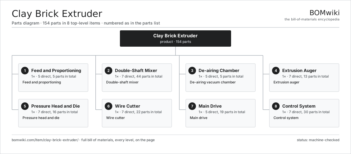
| # | Part | Qty | What it does |
|---|---|---|---|
| 1 | Feed and Proportioning 5 parts | 1× | Feed and proportioning |
| 2 | Double-Shaft Mixer 7 parts | 1× | Double-shaft mixer |
| 3 | De-airing Chamber 5 parts | 1× | De-airing vacuum chamber |
| 4 | Extrusion Auger 7 parts | 1× | Extrusion auger |
| 5 | Pressure Head and Die 7 parts | 1× | Pressure head and die |
| 6 | Wire Cutter 7 parts | 1× | Wire cutter |
| 7 | Main Drive 5 parts | 1× | Main drive |
| 8 | Control System 7 parts | 1× | Control system |
3D model
No 3D model yet. Have a CAD file of this? Add a 3D model. STL renders right on this page; STEP, FreeCAD, and OpenSCAD sources are welcome too (openly licensed, like all 3D models on BOMwiki).
Build & assembly graph
expand / collapse · shared sub-assemblies converge · links to related products · est. labourTap an assembly to expand/collapse · tap a part to open it · use “Open page” for any node · drag to pan, scroll to zoom.
Bill of materials for Clay Brick Extruder
8 top-level lines · 74 rows shown · 154 parts total · indented to 3 levels| # | Item / sub-assembly | Part no. | Qty/assy | Ext. qty | Parts | Type |
|---|---|---|---|---|---|---|
| 1 | Feed and Proportioning 5 parts | clay-brick-extruder-feed | 1× | 1 | 5 | assembly |
| 1.1 | Box Feeder | clay-brick-extruder-box-feeder | 1× | 1 | · | part |
| 1.2 | Apron Feed Belt | clay-brick-extruder-apron-belt | 1× | 1 | · | part |
| 1.3 | Leveling Roller | clay-brick-extruder-leveling-roller | 1× | 1 | · | part |
| 1.4 | Feed Gate | clay-brick-extruder-feed-gate | 1× | 1 | · | part |
| 1.5 | Drive Belt | drive-belt | 1× | 1 | · | part |
| 2 | Double-Shaft Mixer 7 parts | clay-brick-extruder-mixer | 1× | 1 | 44 | assembly |
| 2.1 | Mixer Trough | clay-brick-extruder-mix-trough | 1× | 1 | · | part |
| 2.2 | Paddle Shaft | clay-brick-extruder-mix-shaft | 2× | 2 | · | part |
| 2.3 | Mixing Paddle | clay-brick-extruder-paddle | 24× | 24 | · | part |
| 2.4 | Water Spray Bar | clay-brick-extruder-water-spray | 1× | 1 | · | part |
| 2.5 | Mixer Gearbox 4 parts | clay-brick-extruder-mix-gearbox | 1× | 1 | 8 | assembly |
| 2.5.1 | Gearbox Housing | gearbox-housing | 1× | 1 | · | part |
| 2.5.2 | Helical Gear Pair | gear-pair | 2× | 2 | · | part |
| 2.5.3 | Ball Bearing | ball-bearing | 4× | 4 | · | part |
| 2.5.4 | O-Ring Set | oring-set | 1× | 1 | · | part |
| 2.6 | Ball Bearing | ball-bearing | 4× | 4 | · | part |
| 2.7 | Oil Seal | oil-seal | 4× | 4 | · | part |
| 3 | De-airing Chamber 5 parts | clay-brick-extruder-vacuum | 1× | 1 | 5 | assembly |
| 3.1 | Vacuum Chamber | clay-brick-extruder-vac-chamber | 1× | 1 | · | part |
| 3.2 | Shredding Plate | clay-brick-extruder-shred-plate | 1× | 1 | · | part |
| 3.3 | Vacuum Pump | clay-brick-extruder-vac-pump | 1× | 1 | · | part |
| 3.4 | Chamber Seal | clay-brick-extruder-vac-seal | 1× | 1 | · | part |
| 3.5 | Pressure Sensor | pressure-sensor | 1× | 1 | · | part |
| 4 | Extrusion Auger 7 parts | clay-brick-extruder-auger | 1× | 1 | 13 | assembly |
| 4.1 | Auger Shaft | clay-brick-extruder-auger-shaft | 1× | 1 | · | part |
| 4.2 | Auger Flight | clay-brick-extruder-auger-flight | 6× | 6 | · | part |
| 4.3 | Auger Tip | clay-brick-extruder-auger-tip | 1× | 1 | · | part |
| 4.4 | Extruder Barrel | clay-brick-extruder-barrel | 1× | 1 | · | part |
| 4.5 | Barrel Liner | clay-brick-extruder-barrel-liner | 1× | 1 | · | part |
| 4.6 | Thrust Bearing | clay-brick-extruder-thrust-bearing | 1× | 1 | · | part |
| 4.7 | Oil Seal | oil-seal | 2× | 2 | · | part |
| 5 | Pressure Head and Die 7 parts | clay-brick-extruder-pressure-head | 1× | 1 | 16 | assembly |
| 5.1 | Pressure Head Cone | clay-brick-extruder-head-cone | 1× | 1 | · | part |
| 5.2 | Extrusion Die | clay-brick-extruder-die | 1× | 1 | · | part |
| 5.3 | Die Liner | clay-brick-extruder-die-liner | 1× | 1 | · | part |
| 5.4 | Core Bridge | clay-brick-extruder-core-bridge | 1× | 1 | · | part |
| 5.5 | Core Pin | clay-brick-extruder-core-pin | 10× | 10 | · | part |
| 5.6 | Die Lubricator | clay-brick-extruder-lubricator | 1× | 1 | · | part |
| 5.7 | Fastener Set | fastener-set | 1× | 1 | · | part |
| 6 | Wire Cutter 7 parts | clay-brick-extruder-cutter | 1× | 1 | 22 | assembly |
| 6.1 | Cutting Frame | clay-brick-extruder-cut-frame | 1× | 1 | · | part |
| 6.2 | Cutting Wire | clay-brick-extruder-cut-wire | 12× | 12 | · | part |
| 6.3 | Cutter Carriage | clay-brick-extruder-cut-carriage | 1× | 1 | · | part |
| 6.4 | Cutter Servo | clay-brick-extruder-cut-servo | 1× | 1 | · | part |
| 6.5 | Take-off Belt | clay-brick-extruder-takeoff-belt | 1× | 1 | · | part |
| 6.6 | Linear Guide Rail | linear-guide | 2× | 2 | · | part |
| 6.7 | Coil Spring | coil-spring | 4× | 4 | · | part |
| 7 | Main Drive 5 parts | clay-brick-extruder-drive | 1× | 1 | 19 | assembly |
| 7.1 | Main Motor | clay-brick-extruder-main-motor | 1× | 1 | · | part |
| 7.2 | Main Gearbox 4 parts | clay-brick-extruder-main-gearbox | 1× | 1 | 14 | assembly |
| 7.2.1 | Gearbox Housing | gearbox-housing | 1× | 1 | · | part |
| 7.2.2 | Helical Gear Pair | gear-pair | 3× | 3 | · | part |
| 7.2.3 | Ball Bearing | ball-bearing | 6× | 6 | · | part |
| 7.2.4 | Oil Seal | oil-seal | 4× | 4 | · | part |
| 7.3 | Drive Coupling | clay-brick-extruder-coupling | 1× | 1 | · | part |
| 7.4 | Oil Cooler | clay-brick-extruder-cooling | 1× | 1 | · | part |
| 7.5 | Drive Belt | drive-belt | 2× | 2 | · | part |
| 8 | Control System 7 parts | clay-brick-extruder-control | 1× | 1 | 30 | assembly |
| 8.1 | PLC 4 parts | clay-brick-extruder-plc | 1× | 1 | 8 | assembly |
| 8.1.1 | Microcontroller | mcu | 1× | 1 | · | part |
| 8.1.2 | Bare PCB | pcb-bare | 2× | 2 | · | part |
| 8.1.3 | SMD Passive (R/C/L) | smd-passives | 1× | 1 | · | part |
| 8.1.4 | Relay | relay | 4× | 4 | · | part |
| 8.2 | Operator Panel 4 parts | clay-brick-extruder-hmi | 1× | 1 | 5 | assembly |
| 8.2.1 | LCD Panel | lcd-panel | 1× | 1 | · | part |
| 8.2.2 | Bare PCB | pcb-bare | 1× | 1 | · | part |
| 8.2.3 | Power Supply | power-supply | 1× | 1 | · | part |
| 8.2.4 | Connector | connector | 2× | 2 | · | part |
| 8.3 | Variable Frequency Drive | clay-brick-extruder-vfd | 3× | 3 | · | part |
| 8.4 | Pressure Load Cell | clay-brick-extruder-load-cell | 1× | 1 | · | part |
| 8.5 | Pressure Sensor | pressure-sensor | 2× | 2 | · | part |
| 8.6 | Wire Bundle | wire-bundle | 1× | 1 | · | part |
| 8.7 | Connector | connector | 10× | 10 | · | part |
Related products
same domain, ranked by shared parts Fiber Cement Sheet Machine
819 parts · shares 13 with this page
Fiber Cement Sheet Machine
819 parts · shares 13 with this page
 Gypsum Board Production Line
207 parts · shares 12 with this page
Insulated Sandwich Panel Line
1,856 parts · shares 12 with this page
Concrete Pipe Making Machine
154 parts · shares 11 with this page
Gypsum Board Production Line
207 parts · shares 12 with this page
Insulated Sandwich Panel Line
1,856 parts · shares 12 with this page
Concrete Pipe Making Machine
154 parts · shares 11 with this page
 Paving Block Machine
154 parts · shares 11 with this page
Paving Block Machine
154 parts · shares 11 with this page
 AAC Block Plant
155 parts · shares 11 with this page
AAC Block Plant
155 parts · shares 11 with this page
Sourcing: possible vendors
Browse the supplier directory → Prices, MOQ, and lead times are algorithmic estimates, not quotes, and not claims about these companies. Company mappings are curated by keyword; est. price band $50–$10k. How estimates work| Vendor | HQ | Specialty | MOQ | Lead time |
|---|---|---|---|---|
| assaabloy.com ↗ | Stockholm, SE | Locks & access | 1,000 units | 8–12 wks |
|
🇺🇸Allegion
allegion.com ↗
|
Dublin, US | Security products (Schlage) | 1,000 units | 8–12 wks |
| dormakaba.com ↗ | Rümlang, CH | Access & door systems | 1,000 units | 8–12 wks |
| honeywell.com ↗ | Charlotte, US | Building & safety tech | 1,000 units | 8–12 wks |
| hikvision.com ↗ | Hangzhou, CN | Surveillance & security | 1,000 units | 8–12 wks |
1,008-word article