Geomembrane Welding Machine
ProductOverview
A geomembrane welding machine joins two sheets of plastic liner into one continuous waterproof barrier. It is used to line landfills, mining ponds, canals, and tanks, where the liner has to hold back water or leachate for decades without leaking. The sheets, usually high-density polyethylene or its softer cousin linear low-density polyethylene, come in rolls a few metres wide, so a large cell needs hundreds of seams. This machine makes those seams by the hot-wedge method: it heats a metal wedge, drives that wedge between the overlapping edges of two sheets to melt the facing surfaces, then squeezes the melted surfaces together between two rollers so they fuse as they cool.
The machine is self-propelled. The operator sets it on the overlap, swings the Heated Wedge Assembly in between the sheets, and the Drive System pulls the whole machine forward along the seam at a steady speed while the operator walks behind it with the Handle and Controls. A finished seam is stronger than the sheet itself, so a tear in service will run in the parent material before it opens the weld.
The dual-track seam
The single feature that defines this machine is the dual-track weld. The Wedge Bar does not present one flat hot face. It has two raised tracks separated by a gap, so it melts two parallel weld lines and leaves a narrow unwelded channel running down the middle of the seam. That channel is the reason field crews trust these welds. After a run, an inspector seals both ends of the channel, pushes air into it to a set pressure, and watches a gauge. If the pressure holds, both weld tracks are continuous along the whole length. If it drops, there is a defect somewhere in that stretch and the crew finds it before the cell is filled. No other field weld lets a crew test the entire seam this quickly, which is why dual-track hot-wedge welding is the standard for primary containment seams.
The heated wedge
The heart of the machine is the Heated Wedge Assembly. The Wedge Bar is a copper bar shaped to a wedge so it parts the two sheets and slides between them. Copper is used because it spreads heat evenly and holds a stable temperature across its width, which keeps both weld tracks at the same melt. A Heating Element cartridge sits inside the bar and supplies the heat, and a Wedge Thermocouple buried near the tip reports the real wedge temperature back to the Temperature Controller. That controller switches the heater to hold the wedge at the set point, anywhere from about 250 C for thin sheet on a warm day up to 450 C for thick sheet in the cold. Too cool and the weld is weak; too hot and the wedge burns through the liner. The bar mounts on a Wedge Mount that pivots, so the operator can swing the hot bar clear at the end of a seam, and a Heat Shield Block keeps that heat off the rest of the frame.
Drive and rollers
Heat alone does not make a weld. The melted surfaces have to be pressed together under load, and the machine has to crawl along the seam at a rate that matches the melt. The Drive System handles the crawl. A Geared Drive Motor gearmotor turns the lower roller through a Drive Coupling, and a Speed Encoder reports how fast it is turning so the controller can hold the weld speed steady on flat ground and on the sloped walls of a cell. Typical speeds run from 1 to 5 metres a minute depending on sheet thickness and temperature.
The Roller Assembly applies the pressure. The Upper Drive Roller and Lower Drive Roller are knurled steel rollers that grip the seam right behind the wedge, where the melt is still soft, and squeeze the two tracks together. The force comes from Nip Adjuster screws that compress Coil Spring springs, so the nip force is fixed by spring rate rather than by how hard the operator leans on the machine. Both rollers run on Ball Bearing units in the Side Plate frame. The combination of a set temperature, a set speed, and a set nip force is what makes the seam repeatable from one run to the next.
Control, power, and guidance
The operator works the machine from the Control and Display panel. The Control Board reads the encoder and the thermocouple, drives the motor, and shows the live wedge temperature and weld speed on an LCD Panel display so the operator can confirm both are in range before starting a seam. Weld speed is set with the Speed Potentiometer knob. Power comes through the Power Supply supply: a heavy Power Cord feeds the machine from a site generator, a Residual-Current Device protects the operator on wet ground, and a Power Supply makes the low-voltage rail for the drive and the electronics.
Guidance keeps the seam straight. The Chassis and Guidance carries a Edge Guide Arm with Guide Wheel wheels that ride the edge of the top sheet, holding a constant overlap width as the machine tracks down the seam. The operator walks behind with the Handle and Controls, starting and stopping the drive with the Start Trigger and using the Wedge Engage Lever to swing the wedge in and out. At about 15 kilograms the machine is light enough to lift onto the next seam and carry down into a cell, which matters because a single lining job can run for weeks of welding across a large site.
Geomembrane Welding Machine parts and their functions
7 top-level parts · 273 parts in total · full bill of materials below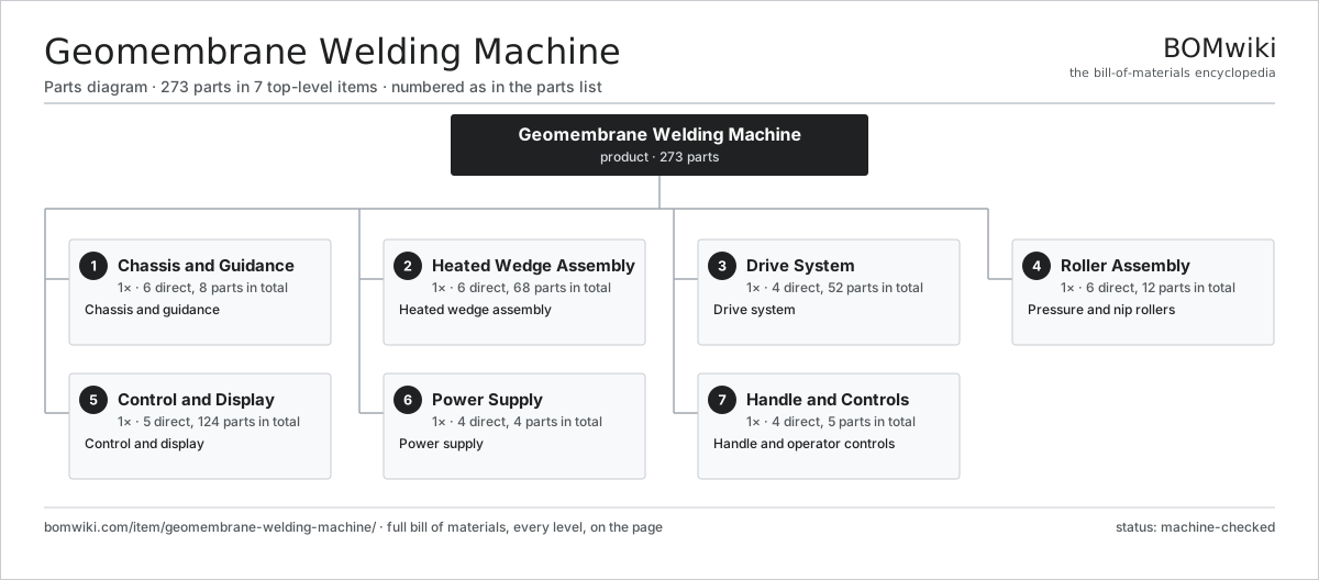
| # | Part | Qty | What it does |
|---|---|---|---|
| 1 | Chassis and Guidance 6 parts | 1× | Chassis and guidance |
| 2 | Heated Wedge Assembly 6 parts | 1× | Heated wedge assembly |
| 3 | Drive System 4 parts | 1× | Drive system |
| 4 | Roller Assembly 6 parts | 1× | Pressure and nip rollers |
| 5 | Control and Display 5 parts | 1× | Control and display |
| 6 | Power Supply 4 parts | 1× | Power supply |
| 7 | Handle and Controls 4 parts | 1× | Handle and operator controls |
3D model
No 3D model yet. Have a CAD file of this? Add a 3D model. STL renders right on this page; STEP, FreeCAD, and OpenSCAD sources are welcome too (openly licensed, like all 3D models on BOMwiki).
Build & assembly graph
expand / collapse · shared sub-assemblies converge · links to related products · est. labourTap an assembly to expand/collapse · tap a part to open it · use “Open page” for any node · drag to pan, scroll to zoom.
Bill of materials for Geomembrane Welding Machine
7 top-level lines · 58 rows shown · 273 parts total · indented to 3 levels| # | Item / sub-assembly | Part no. | Qty/assy | Ext. qty | Parts | Type |
|---|---|---|---|---|---|---|
| 1 | Chassis and Guidance 6 parts | geomembrane-welding-machine-chassis | 1× | 1 | 8 | assembly |
| 1.1 | Main Frame Plate | geomembrane-welding-machine-frame-plate | 1× | 1 | · | part |
| 1.2 | Side Plate | geomembrane-welding-machine-side-plate | 2× | 2 | · | part |
| 1.3 | Edge Guide Arm | geomembrane-welding-machine-guide-arm | 1× | 1 | · | part |
| 1.4 | Guide Wheel | geomembrane-welding-machine-guide-wheel | 2× | 2 | · | part |
| 1.5 | Cooling Fan | geomembrane-welding-machine-cooling-fan | 1× | 1 | · | part |
| 1.6 | Fastener Set | fastener-set | 1× | 1 | · | part |
| 2 | Heated Wedge Assembly 6 parts | geomembrane-welding-machine-wedge-assembly | 1× | 1 | 68 | assembly |
| 2.1 | Wedge Bar | geomembrane-welding-machine-wedge-bar | 1× | 1 | · | part |
| 2.2 | Heating Element | heating-element | 1× | 1 | · | part |
| 2.3 | Wedge Thermocouple | geomembrane-welding-machine-thermocouple | 1× | 1 | · | part |
| 2.4 | Temperature Controller 4 parts | geomembrane-welding-machine-temp-controller | 1× | 1 | 63 | assembly |
| 2.4.1 | Bare PCB | pcb-bare | 1× | 1 | · | part |
| 2.4.2 | Microcontroller | mcu | 1× | 1 | · | part |
| 2.4.3 | Relay | relay | 1× | 1 | · | part |
| 2.4.4 | SMD Passive (R/C/L) | smd-passives | 60× | 60 | · | part |
| 2.5 | Wedge Mount | geomembrane-welding-machine-wedge-mount | 1× | 1 | · | part |
| 2.6 | Heat Shield Block | geomembrane-welding-machine-insulation-block | 1× | 1 | · | part |
| 3 | Drive System 4 parts | geomembrane-welding-machine-drive | 1× | 1 | 52 | assembly |
| 3.1 | Geared Drive Motor 6 parts | geomembrane-welding-machine-drive-motor | 1× | 1 | 28 | assembly |
| 3.1.1 | Stator Assembly 3 parts + deeper › | stator-assembly | 1× | 1 | 3 | assembly |
| 3.1.2 | Rotor Assembly 4 parts + deeper › | rotor-assembly | 1× | 1 | 19 | assembly |
| 3.1.3 | Motor Housing | motor-housing | 1× | 1 | · | part |
| 3.1.4 | Gearbox Housing | gearbox-housing | 1× | 1 | · | part |
| 3.1.5 | Helical Gear Pair | gear-pair | 2× | 2 | · | part |
| 3.1.6 | Ball Bearing | ball-bearing | 2× | 2 | · | part |
| 3.2 | Drive Coupling | geomembrane-welding-machine-drive-coupling | 1× | 1 | · | part |
| 3.3 | Speed Encoder 2 parts | geomembrane-welding-machine-speed-encoder | 1× | 1 | 21 | assembly |
| 3.3.1 | Bare PCB | pcb-bare | 1× | 1 | · | part |
| 3.3.2 | SMD Passive (R/C/L) | smd-passives | 20× | 20 | · | part |
| 3.4 | Ball Bearing | ball-bearing | 2× | 2 | · | part |
| 4 | Roller Assembly 6 parts | geomembrane-welding-machine-roller-assembly | 1× | 1 | 12 | assembly |
| 4.1 | Upper Drive Roller | geomembrane-welding-machine-top-roller | 1× | 1 | · | part |
| 4.2 | Lower Drive Roller | geomembrane-welding-machine-bottom-roller | 1× | 1 | · | part |
| 4.3 | Roller Shaft | geomembrane-welding-machine-roller-shaft | 2× | 2 | · | part |
| 4.4 | Nip Adjuster | geomembrane-welding-machine-pressure-adjuster | 2× | 2 | · | part |
| 4.5 | Coil Spring | coil-spring | 2× | 2 | · | part |
| 4.6 | Ball Bearing | ball-bearing | 4× | 4 | · | part |
| 5 | Control and Display 5 parts | geomembrane-welding-machine-control | 1× | 1 | 124 | assembly |
| 5.1 | Control Board 4 parts | geomembrane-welding-machine-control-board | 1× | 1 | 113 | assembly |
| 5.1.1 | Bare PCB | pcb-bare | 1× | 1 | · | part |
| 5.1.2 | Microcontroller | mcu | 1× | 1 | · | part |
| 5.1.3 | Relay | relay | 1× | 1 | · | part |
| 5.1.4 | SMD Passive (R/C/L) | smd-passives | 110× | 110 | · | part |
| 5.2 | LCD Panel | lcd-panel | 1× | 1 | · | part |
| 5.3 | Speed Potentiometer | geomembrane-welding-machine-speed-pot | 1× | 1 | · | part |
| 5.4 | Wire Bundle | wire-bundle | 1× | 1 | · | part |
| 5.5 | Connector | connector | 8× | 8 | · | part |
| 6 | Power Supply 4 parts | geomembrane-welding-machine-power | 1× | 1 | 4 | assembly |
| 6.1 | Power Supply | power-supply | 1× | 1 | · | part |
| 6.2 | Power Cord | geomembrane-welding-machine-power-cord | 1× | 1 | · | part |
| 6.3 | Main Switch | geomembrane-welding-machine-main-switch | 1× | 1 | · | part |
| 6.4 | Residual-Current Device | geomembrane-welding-machine-rcd | 1× | 1 | · | part |
| 7 | Handle and Controls 4 parts | geomembrane-welding-machine-handle | 1× | 1 | 5 | assembly |
| 7.1 | Handle Bar | geomembrane-welding-machine-handle-bar | 1× | 1 | · | part |
| 7.2 | Start Trigger | geomembrane-welding-machine-trigger | 1× | 1 | · | part |
| 7.3 | Wedge Engage Lever | geomembrane-welding-machine-wedge-lever | 1× | 1 | · | part |
| 7.4 | Hand Grip | geomembrane-welding-machine-handle-grip | 2× | 2 | · | part |
Related products
same domain, ranked by shared parts Precast Concrete Mold
493 parts · shares 15 with this page
Precast Concrete Mold
493 parts · shares 15 with this page
 Fiber Cement Sheet Machine
819 parts · shares 17 with this page
Metal Roofing Roll Former
704 parts · shares 16 with this page
Fiber Cement Sheet Machine
819 parts · shares 17 with this page
Metal Roofing Roll Former
704 parts · shares 16 with this page
 Hollowcore Slab Extruder
547 parts · shares 15 with this page
Hollowcore Slab Extruder
547 parts · shares 15 with this page
 Smart Door Lock
327 parts · shares 15 with this page
Smart Door Lock
327 parts · shares 15 with this page
Sourcing: possible vendors
Browse the supplier directory → Prices, MOQ, and lead times are algorithmic estimates, not quotes, and not claims about these companies. Company mappings are curated by keyword; est. price band $50–$10k. How estimates work| Vendor | HQ | Specialty | MOQ | Lead time |
|---|---|---|---|---|
| assaabloy.com ↗ | Stockholm, SE | Locks & access | 1,000 units | 8–12 wks |
|
🇺🇸Allegion
allegion.com ↗
|
Dublin, US | Security products (Schlage) | 1,000 units | 8–12 wks |
| dormakaba.com ↗ | Rümlang, CH | Access & door systems | 1,000 units | 8–12 wks |
| honeywell.com ↗ | Charlotte, US | Building & safety tech | 1,000 units | 8–12 wks |
| hikvision.com ↗ | Hangzhou, CN | Surveillance & security | 1,000 units | 8–12 wks |
1,008-word article