Precast Concrete Mold
ProductOverview
A precast concrete mold is the steel form a wall panel or structural element is cast in, made flat and stiff enough to give a smooth face and a true edge on every piece. Precast plants run two main forms of it. A tilting table casts the panel flat and then raises it toward vertical so a crane can lift it off, and a battery mold casts several panels at once in vertical slots between movable steel plates. Both share the same job: hold the concrete to shape, compact it, cure it warm so it gains strength overnight, and then let the hardened panel out without damage. This entry covers a tilting table with the Battery Cavity Pack pack as an option, since the two are often built on the same base.
The mold is built around a flat Casting Bed that the panel is poured on. The Side Shutters form the panel edges and any openings. The Tilting Frame lifts the cured panel for demolding, the Vibration System system compacts the wet pour, and the Curing Heat System system cures it. A Hydraulic Power Unit drives the tilt cylinders, the Control Panel panel sequences the cycle, and the Base Frame frame carries the whole table and sets it level.
Casting bed
The casting surface is the part that matters most, because the panel takes its face finish and flatness straight from the steel. The bed uses a ground Sheet Metal Panel face plate carried on a welded Bed Frame of box sections, so the plate stays flat to within about two millimetres over four metres even with a wet load on it. The Leveling Shim Set takes the plate level when the mold is installed, and the Edge Datum Rail datums down each side give the side shutters a square reference to seat against. A layer of Under-Bed Insulation under the plate keeps the curing heat in the concrete rather than letting it drain into the bed frame and the floor.
Side shutters and openings
The panel edges are formed by Shutter Rail profiles set on the bed. Rather than bolt them down for each panel size, the mold holds them with Switchable Shutter Magnet clamps that switch on and off by lever, so an operator can reposition a rail in seconds and cast a different panel width on the same bed. Short rails and odd shapes sit on Magnetic Shuttering Box blocks that grip anywhere on the steel. The corners are squared and sealed by Corner Block pieces, and each rail is pulled tight to the bed by a Shutter Clamp so grout cannot leak under it and spoil the edge. Window and door openings are left by Blockout Form forms set inside the panel outline before the pour.
Compaction and curing
Wet concrete has to be compacted or it cures full of voids that weaken the panel and mark the face. The Vibration System system does this with External Vibrator Motor motors clamped under the bed on Vibrator Bracket brackets. Each motor spins a pair of Eccentric Weight weights so its rotation becomes vibration that carries through the steel into the concrete, and the throw of the weights sets the force. The vibrator is built from a Stator Assembly and a Rotor Assembly like any motor, on Ball Bearing supports. The Isolation Mount springs under the bed keep the shaking in the table and out of the slab. The Vibration Controller runs the motors in short bursts so the mix consolidates without the aggregate settling out.
Once compacted, the panel is cured warm to reach lifting strength by the next shift. The Curing Heat System system runs warm water or thermal oil through Heating Pipe runs welded under the face plate, backed by Heating Element mats. A Curing Cover insulated blanket holds the heat and moisture over the top of the panel. Temperature Probe probes track the steel and the concrete so the curing thermostat in the Heating Contactor Box box can hold the bed around fifty degrees and ramp it on a profile instead of cooking the surface.
Tilting and demolding
A flat panel cannot be lifted straight up without cracking it, so the Tilting Frame raises the cured panel toward vertical first. The Tilting Table swings on a row of Hinge Line pins along one edge while the Tilt Cylinder cylinders push it up to around eighty degrees, where a Tilt Stop catches it and the Angle Sensor confirms the angle. Each cylinder runs a chromed Cylinder Rod in a honed Cylinder Tube, sealed by an O-Ring Set and pinned through Rod Eye eyes so it can swing as the table rises. Near vertical, the panel hangs on its own weight against the steel and parts cleanly when the crane takes it on the cast-in lifting anchors.
Hydraulics, control, and tooling
The Hydraulic Power Unit supplies the tilt force. A Hydraulic Pump driven by its motor draws from the Oil Reservoir and feeds the Valve Manifold, which meters flow so all the cylinders rise together and the table stays square, with Pressure Sensor units watching the line. The Control Panel panel ties it together: a PLC and I/O times the vibration, holds the curing profile, and steps the tilt cycle, while the operator picks the panel and program at the Operator Touchscreen. A hard-wired Emergency Stop Circuit drops pressure and stops the vibrators if anything goes wrong.
Two things make the panel usable on site. The Insert Setting Jig locates the lifting anchors and cast-in sockets before the pour, and the Release Agent Sprayer lays a thin film of release agent so the panel parts from the steel. Between casts the bed is cleared with the Bed Cleaning Scraper scraper set so the next panel takes a clean flat face. For higher output the Battery Cavity Pack pack casts several panels upright at once between Cavity Plate plates that ride on Linear Guide Rail rails and are driven open and shut by Ball Screw screws under Servo Motor control.
Precast Concrete Mold parts and their functions
10 top-level parts · 493 parts in total · full bill of materials below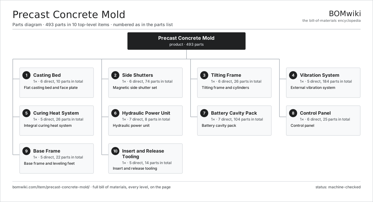
| # | Part | Qty | What it does |
|---|---|---|---|
| 1 | Casting Bed 6 parts | 1× | Flat casting bed and face plate |
| 2 | Side Shutters 6 parts | 1× | Magnetic side shutter set |
| 3 | Tilting Frame 6 parts | 1× | Tilting frame and cylinders |
| 4 | Vibration System 5 parts | 1× | External vibration system |
| 5 | Curing Heat System 5 parts | 1× | Integral curing heat system |
| 6 | Hydraulic Power Unit 7 parts | 1× | Hydraulic power unit |
| 7 | Battery Cavity Pack 7 parts | 1× | Battery cavity pack |
| 8 | Control Panel 6 parts | 1× | Control panel |
| 9 | Base Frame 5 parts | 1× | Base frame and leveling feet |
| 10 | Insert and Release Tooling 5 parts | 1× | Insert and release tooling |
3D model
No 3D model yet. Have a CAD file of this? Add a 3D model. STL renders right on this page; STEP, FreeCAD, and OpenSCAD sources are welcome too (openly licensed, like all 3D models on BOMwiki).
Build & assembly graph
expand / collapse · shared sub-assemblies converge · links to related products · est. labourTap an assembly to expand/collapse · tap a part to open it · use “Open page” for any node · drag to pan, scroll to zoom.
Bill of materials for Precast Concrete Mold
10 top-level lines · 92 rows shown · 493 parts total · indented to 3 levels| # | Item / sub-assembly | Part no. | Qty/assy | Ext. qty | Parts | Type |
|---|---|---|---|---|---|---|
| 1 | Casting Bed 6 parts | precast-concrete-mold-casting-bed | 1× | 1 | 10 | assembly |
| 1.1 | Sheet Metal Panel | sheet-panel | 1× | 1 | · | part |
| 1.2 | Bed Frame | precast-concrete-mold-bed-frame | 1× | 1 | · | part |
| 1.3 | Edge Datum Rail | precast-concrete-mold-edge-rail | 4× | 4 | · | part |
| 1.4 | Under-Bed Insulation | precast-concrete-mold-insulation | 1× | 1 | · | part |
| 1.5 | Leveling Shim Set | precast-concrete-mold-shim-set | 1× | 1 | · | part |
| 1.6 | Fastener Set | fastener-set | 2× | 2 | · | part |
| 2 | Side Shutters 6 parts | precast-concrete-mold-side-shutters | 1× | 1 | 74 | assembly |
| 2.1 | Shutter Rail | precast-concrete-mold-shutter-rail | 8× | 8 | · | part |
| 2.2 | Switchable Shutter Magnet | precast-concrete-mold-shutter-magnet | 24× | 24 | · | part |
| 2.3 | Magnetic Shuttering Box | precast-concrete-mold-magnet-box | 12× | 12 | · | part |
| 2.4 | Corner Block | precast-concrete-mold-corner-block | 8× | 8 | · | part |
| 2.5 | Shutter Clamp | precast-concrete-mold-shutter-clamp | 16× | 16 | · | part |
| 2.6 | Blockout Form | precast-concrete-mold-blockout | 6× | 6 | · | part |
| 3 | Tilting Frame 6 parts | precast-concrete-mold-tilting-frame | 1× | 1 | 26 | assembly |
| 3.1 | Tilting Table | precast-concrete-mold-tilt-table | 1× | 1 | · | part |
| 3.2 | Hinge Line | precast-concrete-mold-hinge-set | 1× | 1 | · | part |
| 3.3 | Tilt Cylinder 4 parts | precast-concrete-mold-tilt-cylinder | 4× | 4 | 5 | assembly |
| 3.3.1 | Cylinder Tube | precast-concrete-mold-cyl-tube | 1× | 4 | · | part |
| 3.3.2 | Cylinder Rod | precast-concrete-mold-cyl-rod | 1× | 4 | · | part |
| 3.3.3 | O-Ring Set | oring-set | 1× | 4 | · | part |
| 3.3.4 | Rod Eye | precast-concrete-mold-rod-eye | 2× | 8 | · | part |
| 3.4 | Tilt Stop | precast-concrete-mold-tilt-stop | 2× | 2 | · | part |
| 3.5 | Angle Sensor | precast-concrete-mold-angle-sensor | 1× | 1 | · | part |
| 3.6 | Fastener Set | fastener-set | 1× | 1 | · | part |
| 4 | Vibration System 5 parts | precast-concrete-mold-vibration | 1× | 1 | 184 | assembly |
| 4.1 | External Vibrator Motor 5 parts | precast-concrete-mold-vibrator | 6× | 6 | 28 | assembly |
| 4.1.1 | Stator Assembly 3 parts + deeper › | stator-assembly | 1× | 6 | 3 | assembly |
| 4.1.2 | Rotor Assembly 4 parts + deeper › | rotor-assembly | 1× | 6 | 19 | assembly |
| 4.1.3 | Eccentric Weight | precast-concrete-mold-eccentric | 2× | 12 | · | part |
| 4.1.4 | Ball Bearing | ball-bearing | 2× | 12 | · | part |
| 4.1.5 | Oil Seal | oil-seal | 2× | 12 | · | part |
| 4.2 | Vibrator Bracket | precast-concrete-mold-vib-mount | 6× | 6 | · | part |
| 4.3 | Isolation Mount | precast-concrete-mold-iso-mount | 8× | 8 | · | part |
| 4.4 | Vibration Controller | precast-concrete-mold-vib-controller | 1× | 1 | · | part |
| 4.5 | Fastener Set | fastener-set | 1× | 1 | · | part |
| 5 | Curing Heat System 5 parts | precast-concrete-mold-heating | 1× | 1 | 26 | assembly |
| 5.1 | Heating Element | heating-element | 1× | 1 | · | part |
| 5.2 | Heating Pipe | precast-concrete-mold-heat-pipe | 8× | 8 | · | part |
| 5.3 | Temperature Probe | precast-concrete-mold-temp-probe | 4× | 4 | · | part |
| 5.4 | Curing Cover | precast-concrete-mold-heat-cover | 1× | 1 | · | part |
| 5.5 | Heating Contactor Box 4 parts | precast-concrete-mold-heat-relay | 1× | 1 | 12 | assembly |
| 5.5.1 | Relay | relay | 4× | 4 | · | part |
| 5.5.2 | Curing Thermostat | precast-concrete-mold-thermostat | 1× | 1 | · | part |
| 5.5.3 | Connector | connector | 6× | 6 | · | part |
| 5.5.4 | Wire Bundle | wire-bundle | 1× | 1 | · | part |
| 6 | Hydraulic Power Unit 7 parts | precast-concrete-mold-hpu | 1× | 1 | 8 | assembly |
| 6.1 | Hydraulic Pump | precast-concrete-mold-hyd-pump | 1× | 1 | · | part |
| 6.2 | Pump Motor | precast-concrete-mold-hyd-motor | 1× | 1 | · | part |
| 6.3 | Oil Reservoir | precast-concrete-mold-oil-tank | 1× | 1 | · | part |
| 6.4 | Valve Manifold | precast-concrete-mold-valve-block | 1× | 1 | · | part |
| 6.5 | Return Filter | precast-concrete-mold-oil-filter | 1× | 1 | · | part |
| 6.6 | Pressure Sensor | pressure-sensor | 2× | 2 | · | part |
| 6.7 | O-Ring Set | oring-set | 1× | 1 | · | part |
| 7 | Battery Cavity Pack 7 parts | precast-concrete-mold-battery | 1× | 1 | 104 | assembly |
| 7.1 | Cavity Plate | precast-concrete-mold-cavity-plate | 12× | 12 | · | part |
| 7.2 | Plate Carriage | precast-concrete-mold-plate-carriage | 12× | 12 | · | part |
| 7.3 | Clamping Screw | precast-concrete-mold-clamp-screw | 4× | 4 | · | part |
| 7.4 | Cavity Spacer | precast-concrete-mold-spacer | 22× | 22 | · | part |
| 7.5 | Linear Guide Rail | linear-guide | 4× | 4 | · | part |
| 7.6 | Ball Screw | ball-screw | 2× | 2 | · | part |
| 7.7 | Servo Motor 4 parts | servo-motor | 2× | 2 | 24 | assembly |
| 7.7.1 | Stator Assembly 3 parts + deeper › | stator-assembly | 1× | 2 | 3 | assembly |
| 7.7.2 | Rotor Assembly 4 parts + deeper › | rotor-assembly | 1× | 2 | 19 | assembly |
| 7.7.3 | Encoder | encoder | 1× | 2 | · | part |
| 7.7.4 | Motor Housing | motor-housing | 1× | 2 | · | part |
| 8 | Control Panel 6 parts | precast-concrete-mold-control | 1× | 1 | 25 | assembly |
| 8.1 | PLC and I/O 4 parts | precast-concrete-mold-plc | 1× | 1 | 10 | assembly |
| 8.1.1 | Bare PCB | pcb-bare | 2× | 2 | · | part |
| 8.1.2 | Microcontroller | mcu | 1× | 1 | · | part |
| 8.1.3 | SMD Passive (R/C/L) | smd-passives | 1× | 1 | · | part |
| 8.1.4 | Connector | connector | 6× | 6 | · | part |
| 8.2 | Operator Touchscreen 3 parts | precast-concrete-mold-hmi | 1× | 1 | 4 | assembly |
| 8.2.1 | LCD Panel | lcd-panel | 1× | 1 | · | part |
| 8.2.2 | Bare PCB | pcb-bare | 1× | 1 | · | part |
| 8.2.3 | Connector | connector | 2× | 2 | · | part |
| 8.3 | Power Supply | power-supply | 1× | 1 | · | part |
| 8.4 | Relay | relay | 8× | 8 | · | part |
| 8.5 | Emergency Stop Circuit | precast-concrete-mold-estop | 1× | 1 | · | part |
| 8.6 | Wire Bundle | wire-bundle | 1× | 1 | · | part |
| 9 | Base Frame 5 parts | precast-concrete-mold-base | 1× | 1 | 22 | assembly |
| 9.1 | Base Weldment | precast-concrete-mold-base-weldment | 1× | 1 | · | part |
| 9.2 | Leveling Foot | precast-concrete-mold-leveling-foot | 8× | 8 | · | part |
| 9.3 | Floor Anchor | precast-concrete-mold-anchor | 8× | 8 | · | part |
| 9.4 | Cylinder Base Mount | precast-concrete-mold-cyl-mount | 4× | 4 | · | part |
| 9.5 | Fastener Set | fastener-set | 1× | 1 | · | part |
| 10 | Insert and Release Tooling 5 parts | precast-concrete-mold-tooling | 1× | 1 | 14 | assembly |
| 10.1 | Insert Setting Jig | precast-concrete-mold-insert-jig | 2× | 2 | · | part |
| 10.2 | Recess Former | precast-concrete-mold-magnet-recess | 8× | 8 | · | part |
| 10.3 | Release Agent Sprayer | precast-concrete-mold-release-sprayer | 1× | 1 | · | part |
| 10.4 | Demolding Bar | precast-concrete-mold-demold-bar | 2× | 2 | · | part |
| 10.5 | Bed Cleaning Scraper | precast-concrete-mold-cleaning-tool | 1× | 1 | · | part |
Related products
same domain, ranked by shared parts Fiber Cement Sheet Machine
819 parts · shares 20 with this page
Fiber Cement Sheet Machine
819 parts · shares 20 with this page
 Tunnel Form System
559 parts · shares 14 with this page
Tunnel Form System
559 parts · shares 14 with this page
 Gypsum Board Production Line
207 parts · shares 11 with this page
Roof Tile Press
443 parts · shares 17 with this page
Gypsum Board Production Line
207 parts · shares 11 with this page
Roof Tile Press
443 parts · shares 17 with this page
 Geomembrane Welding Machine
273 parts · shares 15 with this page
Geomembrane Welding Machine
273 parts · shares 15 with this page
Sourcing: possible vendors
Browse the supplier directory → Prices, MOQ, and lead times are algorithmic estimates, not quotes, and not claims about these companies. Company mappings are curated by keyword; est. price band $50–$10k. How estimates work| Vendor | HQ | Specialty | MOQ | Lead time |
|---|---|---|---|---|
| assaabloy.com ↗ | Stockholm, SE | Locks & access | 1,000 units | 8–12 wks |
|
🇺🇸Allegion
allegion.com ↗
|
Dublin, US | Security products (Schlage) | 1,000 units | 8–12 wks |
| dormakaba.com ↗ | Rümlang, CH | Access & door systems | 1,000 units | 8–12 wks |
| honeywell.com ↗ | Charlotte, US | Building & safety tech | 1,000 units | 8–12 wks |
| hikvision.com ↗ | Hangzhou, CN | Surveillance & security | 1,000 units | 8–12 wks |
1,127-word article