Hollowcore Slab Extruder
ProductOverview
A hollowcore slab extruder casts prestressed concrete floor planks in one continuous pour. It is a self-propelled machine that sits on the side rails of a long prestressing bed, straddling a row of steel strands that have already been pulled to high tension along the full length of the bed. As the machine creeps forward it takes in stiff, almost dry concrete, forces it around a set of cores that form the hollow voids, vibrates it solid, and trowels the cross-section to shape. Behind the machine it leaves a finished plank with the strands cast into it. When the bed is full the plank is cured, the strands are cut, and the long casting is saw-cut into floor units of the lengths a building needs.
The work splits across nine subsystems. The Concrete Hopper and Feed takes the concrete charge and meters it down, the Auger and Mandrel Forming Section forces it around the cores and forms the voids, and the Vibration and Compaction System system compacts it. The Drive and Traction System system pulls the machine along the bed, the Slipform Shoe and Side Forms shoe shapes the finished surfaces, and the Prestress Strand Pass-Through lets the machine pass over the tensioned strands cleanly. The Electric Power Unit unit feeds the motors, the Control Panel panel keeps casting speed and feed in balance, and the Machine Frame and Rail Wheels carries it all on the rails.
Feeding the concrete
Hollow-core planks are dry-cast, which means the mix has almost no slump and will not flow under its own weight. It has to be pushed. The Concrete Hopper and Feed holds a charge dropped in by an overhead skip, and two vertical Feed Screw augers drag that stiff concrete down out of the hopper and deliver it to the forming section at a steady rate. The screws turn through the Feed Screw Gearbox, driven by the Feed Screw Motor, at low speed and high torque because the mix resists being moved. A Level Paddle in the hopper signals when the charge runs low so the operator calls the next skip before the feed starves and leaves a void in the plank.
Forming the voids
The heart of the machine is the Auger and Mandrel Forming Section. A row of helical Forming Auger screws turns inside a hard Forming Chamber Liner, and each auger drags concrete back along the machine as the whole machine advances forward. That back-pressure is what packs the dry mix solid. Trailing behind each auger is a floating Core Mandrel that holds one void open while the concrete sets around it, and a Compaction Tube that shapes and consolidates the concrete around that void. The augers run on hardened Auger Shaft shafts carried on Ball Bearing units and sealed against grout by Oil Seal rings. All of the augers are driven in step from the Auger Drive Gearbox, which splits the torque of the Auger Drive Motor motors across every shaft so the cores form evenly across the width of the slab. A slab 1200 mm wide carries four to seven cores depending on its depth.
Compaction
Dry-cast concrete traps a lot of air, and the only way to drive it out is vibration. The Vibration and Compaction System system runs high-frequency vibrators inside the cores and along the edges. A Mandrel Vibrator sits inside each core mandrel and consolidates the concrete around the void, while a Side Form Vibrator on each side compacts the webs and edges. Each one is driven by a Vibrator Motor spinning a Eccentric Weight weight, and the eccentric setting tunes how hard the unit shakes. Good compaction sets the strength of the plank, so this system runs continuously while concrete is being placed.
Driving along the bed
The machine moves itself. The Drive and Traction System system has powered Driven Rail Wheel wheels that grip the bed rail, turned by the Traction Motor through the Traction Gearbox at a slow creep of one to two and a half metres per minute. The forward speed has to match the rate the augers can pack concrete, so a Casting Speed Sensor reports the travel speed and the control trims it against the feed. A Holding Brake locks the machine when it stops so it cannot roll back into the fresh plank. As the machine advances it has to pass cleanly over the tensioned strands: the Prestress Strand Pass-Through holds each strand on its line with a Strand Entry Comb and a row of Strand Guide Roller rollers so the auger cannot drag the steel off position.
Finishing and control
The Slipform Shoe and Side Forms shoe trails behind the forming section and sets the final shape. The Top Forming Shoe forms the flat deck, the Side Form plates form the keyed edges that grout to the next plank on site, and the Top Screed Plate floats the top smooth. Slab depth is set by raising or lowering the forming section on its Slab Depth Adjuster screws. Power reaches the motors through the Electric Power Unit unit, where Variable Frequency Drive drives set each speed and a Trailing Cable Reel pays out the supply cable along the bed, backed by a Power Supply and interface Relay units. The Control Panel panel ties it together: a Machine Controller balances feed, auger, and traction speed against the chamber Pressure Sensor reading, an LCD Panel shows the operator the casting state, and a hard-wired Emergency Stop Circuit circuit cuts everything at once. The result is a long, dense, prestressed plank that needs no formwork under it and spans far further than a solid slab of the same weight.
Hollowcore Slab Extruder parts and their functions
9 top-level parts · 547 parts in total · full bill of materials below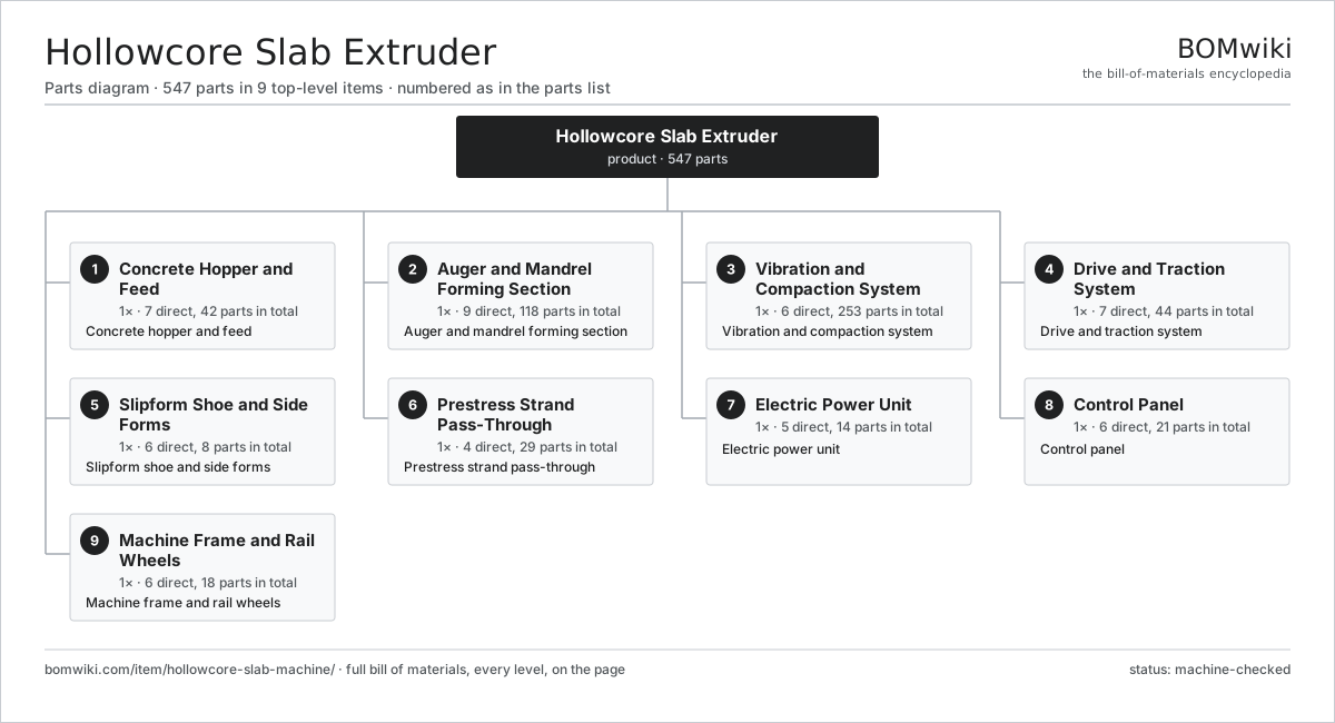
| # | Part | Qty | What it does |
|---|---|---|---|
| 1 | Concrete Hopper and Feed 7 parts | 1× | Concrete hopper and feed |
| 2 | Auger and Mandrel Forming Section 9 parts | 1× | Auger and mandrel forming section |
| 3 | Vibration and Compaction System 6 parts | 1× | Vibration and compaction system |
| 4 | Drive and Traction System 7 parts | 1× | Drive and traction system |
| 5 | Slipform Shoe and Side Forms 6 parts | 1× | Slipform shoe and side forms |
| 6 | Prestress Strand Pass-Through 4 parts | 1× | Prestress strand pass-through |
| 7 | Electric Power Unit 5 parts | 1× | Electric power unit |
| 8 | Control Panel 6 parts | 1× | Control panel |
| 9 | Machine Frame and Rail Wheels 6 parts | 1× | Machine frame and rail wheels |
3D model
No 3D model yet. Have a CAD file of this? Add a 3D model. STL renders right on this page; STEP, FreeCAD, and OpenSCAD sources are welcome too (openly licensed, like all 3D models on BOMwiki).
Build & assembly graph
expand / collapse · shared sub-assemblies converge · links to related products · est. labourTap an assembly to expand/collapse · tap a part to open it · use “Open page” for any node · drag to pan, scroll to zoom.
Bill of materials for Hollowcore Slab Extruder
9 top-level lines · 94 rows shown · 547 parts total · indented to 3 levels| # | Item / sub-assembly | Part no. | Qty/assy | Ext. qty | Parts | Type |
|---|---|---|---|---|---|---|
| 1 | Concrete Hopper and Feed 7 parts | hollowcore-slab-machine-hopper | 1× | 1 | 42 | assembly |
| 1.1 | Hopper Body | hollowcore-slab-machine-hopper-body | 1× | 1 | · | part |
| 1.2 | Feed Screw | hollowcore-slab-machine-feed-screw | 2× | 2 | · | part |
| 1.3 | Feed Screw Gearbox 4 parts | hollowcore-slab-machine-feed-gearbox | 1× | 1 | 9 | assembly |
| 1.3.1 | Helical Gear Pair | gear-pair | 2× | 2 | · | part |
| 1.3.2 | Gearbox Housing | gearbox-housing | 1× | 1 | · | part |
| 1.3.3 | Ball Bearing | ball-bearing | 4× | 4 | · | part |
| 1.3.4 | Oil Seal | oil-seal | 2× | 2 | · | part |
| 1.4 | Feed Screw Motor 3 parts | hollowcore-slab-machine-feed-motor | 1× | 1 | 24 | assembly |
| 1.4.1 | Stator Assembly 3 parts + deeper › | stator-assembly | 1× | 1 | 3 | assembly |
| 1.4.2 | Rotor Assembly 4 parts + deeper › | rotor-assembly | 1× | 1 | 19 | assembly |
| 1.4.3 | Ball Bearing | ball-bearing | 2× | 2 | · | part |
| 1.5 | Level Paddle | hollowcore-slab-machine-level-paddle | 1× | 1 | · | part |
| 1.6 | Sheet Metal Panel | sheet-panel | 4× | 4 | · | part |
| 1.7 | Fastener Set | fastener-set | 1× | 1 | · | part |
| 2 | Auger and Mandrel Forming Section 9 parts | hollowcore-slab-machine-auger-section | 1× | 1 | 118 | assembly |
| 2.1 | Forming Auger | hollowcore-slab-machine-forming-auger | 5× | 5 | · | part |
| 2.2 | Core Mandrel | hollowcore-slab-machine-mandrel-tube | 5× | 5 | · | part |
| 2.3 | Compaction Tube | hollowcore-slab-machine-compaction-tube | 5× | 5 | · | part |
| 2.4 | Auger Shaft | hollowcore-slab-machine-auger-shaft | 5× | 5 | · | part |
| 2.5 | Auger Drive Gearbox 4 parts | hollowcore-slab-machine-auger-gearbox | 1× | 1 | 25 | assembly |
| 2.5.1 | Helical Gear Pair | gear-pair | 6× | 6 | · | part |
| 2.5.2 | Gearbox Housing | gearbox-housing | 1× | 1 | · | part |
| 2.5.3 | Ball Bearing | ball-bearing | 12× | 12 | · | part |
| 2.5.4 | Oil Seal | oil-seal | 6× | 6 | · | part |
| 2.6 | Auger Drive Motor 4 parts | hollowcore-slab-machine-auger-motor | 2× | 2 | 26 | assembly |
| 2.6.1 | Stator Assembly 3 parts + deeper › | stator-assembly | 1× | 2 | 3 | assembly |
| 2.6.2 | Rotor Assembly 4 parts + deeper › | rotor-assembly | 1× | 2 | 19 | assembly |
| 2.6.3 | Ball Bearing | ball-bearing | 2× | 4 | · | part |
| 2.6.4 | Drive Belt | drive-belt | 2× | 4 | · | part |
| 2.7 | Forming Chamber Liner | hollowcore-slab-machine-wear-liner | 1× | 1 | · | part |
| 2.8 | Ball Bearing | ball-bearing | 10× | 10 | · | part |
| 2.9 | Oil Seal | oil-seal | 10× | 10 | · | part |
| 3 | Vibration and Compaction System 6 parts | hollowcore-slab-machine-vibration | 1× | 1 | 253 | assembly |
| 3.1 | Mandrel Vibrator | hollowcore-slab-machine-mandrel-vibrator | 5× | 5 | · | part |
| 3.2 | Side Form Vibrator | hollowcore-slab-machine-form-vibrator | 4× | 4 | · | part |
| 3.3 | Vibrator Motor 3 parts | hollowcore-slab-machine-vibrator-motor | 9× | 9 | 24 | assembly |
| 3.3.1 | Stator Assembly 3 parts + deeper › | stator-assembly | 1× | 9 | 3 | assembly |
| 3.3.2 | Rotor Assembly 4 parts + deeper › | rotor-assembly | 1× | 9 | 19 | assembly |
| 3.3.3 | Ball Bearing | ball-bearing | 2× | 18 | · | part |
| 3.4 | Eccentric Weight | hollowcore-slab-machine-eccentric | 9× | 9 | · | part |
| 3.5 | Ball Bearing | ball-bearing | 18× | 18 | · | part |
| 3.6 | Wire Bundle | wire-bundle | 1× | 1 | · | part |
| 4 | Drive and Traction System 7 parts | hollowcore-slab-machine-traction | 1× | 1 | 44 | assembly |
| 4.1 | Driven Rail Wheel | hollowcore-slab-machine-drive-wheel | 2× | 2 | · | part |
| 4.2 | Traction Motor 3 parts | hollowcore-slab-machine-traction-motor | 1× | 1 | 24 | assembly |
| 4.2.1 | Stator Assembly 3 parts + deeper › | stator-assembly | 1× | 1 | 3 | assembly |
| 4.2.2 | Rotor Assembly 4 parts + deeper › | rotor-assembly | 1× | 1 | 19 | assembly |
| 4.2.3 | Ball Bearing | ball-bearing | 2× | 2 | · | part |
| 4.3 | Traction Gearbox 4 parts | hollowcore-slab-machine-traction-gearbox | 1× | 1 | 10 | assembly |
| 4.3.1 | Helical Gear Pair | gear-pair | 3× | 3 | · | part |
| 4.3.2 | Gearbox Housing | gearbox-housing | 1× | 1 | · | part |
| 4.3.3 | Ball Bearing | ball-bearing | 4× | 4 | · | part |
| 4.3.4 | Oil Seal | oil-seal | 2× | 2 | · | part |
| 4.4 | Casting Speed Sensor | hollowcore-slab-machine-speed-sensor | 1× | 1 | · | part |
| 4.5 | Holding Brake | hollowcore-slab-machine-brake | 1× | 1 | · | part |
| 4.6 | Drive Belt | drive-belt | 2× | 2 | · | part |
| 4.7 | Ball Bearing | ball-bearing | 4× | 4 | · | part |
| 5 | Slipform Shoe and Side Forms 6 parts | hollowcore-slab-machine-slipform | 1× | 1 | 8 | assembly |
| 5.1 | Top Forming Shoe | hollowcore-slab-machine-top-shoe | 1× | 1 | · | part |
| 5.2 | Side Form | hollowcore-slab-machine-side-form | 2× | 2 | · | part |
| 5.3 | Top Screed Plate | hollowcore-slab-machine-screed | 1× | 1 | · | part |
| 5.4 | Soffit Wear Plate | hollowcore-slab-machine-soffit-plate | 1× | 1 | · | part |
| 5.5 | Slab Depth Adjuster | hollowcore-slab-machine-height-adjuster | 2× | 2 | · | part |
| 5.6 | Fastener Set | fastener-set | 1× | 1 | · | part |
| 6 | Prestress Strand Pass-Through 4 parts | hollowcore-slab-machine-strand-guide | 1× | 1 | 29 | assembly |
| 6.1 | Strand Entry Comb | hollowcore-slab-machine-strand-comb | 1× | 1 | · | part |
| 6.2 | Strand Guide Roller | hollowcore-slab-machine-strand-roller | 7× | 7 | · | part |
| 6.3 | Parting Blade | hollowcore-slab-machine-parting-blade | 7× | 7 | · | part |
| 6.4 | Ball Bearing | ball-bearing | 14× | 14 | · | part |
| 7 | Electric Power Unit 5 parts | hollowcore-slab-machine-power | 1× | 1 | 14 | assembly |
| 7.1 | Variable Frequency Drive | hollowcore-slab-machine-vfd | 3× | 3 | · | part |
| 7.2 | Trailing Cable Reel | hollowcore-slab-machine-cable-reel | 1× | 1 | · | part |
| 7.3 | Power Supply | power-supply | 1× | 1 | · | part |
| 7.4 | Relay | relay | 8× | 8 | · | part |
| 7.5 | Wire Bundle | wire-bundle | 1× | 1 | · | part |
| 8 | Control Panel 6 parts | hollowcore-slab-machine-control | 1× | 1 | 21 | assembly |
| 8.1 | Machine Controller 4 parts | hollowcore-slab-machine-controller | 1× | 1 | 10 | assembly |
| 8.1.1 | Bare PCB | pcb-bare | 2× | 2 | · | part |
| 8.1.2 | Microcontroller | mcu | 1× | 1 | · | part |
| 8.1.3 | SMD Passive (R/C/L) | smd-passives | 1× | 1 | · | part |
| 8.1.4 | Connector | connector | 6× | 6 | · | part |
| 8.2 | LCD Panel | lcd-panel | 1× | 1 | · | part |
| 8.3 | Pressure Sensor | pressure-sensor | 2× | 2 | · | part |
| 8.4 | Relay | relay | 6× | 6 | · | part |
| 8.5 | Emergency Stop Circuit | hollowcore-slab-machine-estop | 1× | 1 | · | part |
| 8.6 | Wire Bundle | wire-bundle | 1× | 1 | · | part |
| 9 | Machine Frame and Rail Wheels 6 parts | hollowcore-slab-machine-chassis | 1× | 1 | 18 | assembly |
| 9.1 | Frame Weldment | hollowcore-slab-machine-frame-weldment | 1× | 1 | · | part |
| 9.2 | Idle Rail Wheel | hollowcore-slab-machine-idle-wheel | 2× | 2 | · | part |
| 9.3 | Crane Lift Lug | hollowcore-slab-machine-lift-lug | 4× | 4 | · | part |
| 9.4 | Sheet Metal Panel | sheet-panel | 6× | 6 | · | part |
| 9.5 | Ball Bearing | ball-bearing | 4× | 4 | · | part |
| 9.6 | Fastener Set | fastener-set | 1× | 1 | · | part |
Related products
same domain, ranked by shared parts Fiber Cement Sheet Machine
819 parts · shares 18 with this page
Insulated Sandwich Panel Line
1,856 parts · shares 18 with this page
Metal Roofing Roll Former
704 parts · shares 17 with this page
Fiber Cement Sheet Machine
819 parts · shares 18 with this page
Insulated Sandwich Panel Line
1,856 parts · shares 18 with this page
Metal Roofing Roll Former
704 parts · shares 17 with this page
 Precast Concrete Mold
493 parts · shares 16 with this page
Roof Tile Press
443 parts · shares 15 with this page
Precast Concrete Mold
493 parts · shares 16 with this page
Roof Tile Press
443 parts · shares 15 with this page
 Garage Door Opener
280 parts · shares 14 with this page
Garage Door Opener
280 parts · shares 14 with this page
Sourcing: possible vendors
Browse the supplier directory → Prices, MOQ, and lead times are algorithmic estimates, not quotes, and not claims about these companies. Company mappings are curated by keyword; est. price band $50–$10k. How estimates work| Vendor | HQ | Specialty | MOQ | Lead time |
|---|---|---|---|---|
| assaabloy.com ↗ | Stockholm, SE | Locks & access | 1,000 units | 8–12 wks |
|
🇺🇸Allegion
allegion.com ↗
|
Dublin, US | Security products (Schlage) | 1,000 units | 8–12 wks |
| dormakaba.com ↗ | Rümlang, CH | Access & door systems | 1,000 units | 8–12 wks |
| honeywell.com ↗ | Charlotte, US | Building & safety tech | 1,000 units | 8–12 wks |
| hikvision.com ↗ | Hangzhou, CN | Surveillance & security | 1,000 units | 8–12 wks |
1,026-word article