Air-Jet Spinning Machine
ProductOverview
An air-jet spinning machine makes yarn far faster than a ring frame by replacing the spinning ring and traveller with two small air nozzles. In ring spinning a metal traveller has to circle the package thousands of times a minute to put twist in, and the speed of that traveller is the hard ceiling on output. Air-jet spinning has no rotating mechanical part in the twisting zone at all. It twists the fiber with swirling air, so each position can deliver yarn at three to five times ring-frame speed, in the range of 300 to 550 metres a minute.
The yarn it makes is not a true twisted yarn. It is a fasciated yarn: a straight, untwisted core of parallel fibers held together by a tight wrapping of edge fibers spun around the outside. This gives a clean, low-hairiness yarn that resists pilling and runs well in weaving and knitting, which is why air-jet yarn is common in shirting, bedsheets and blended polyester-cotton fabrics.
How it works
Sliver from cans on the Sliver Creel & Feed feeds up into a Drafting Unit unit, where four lines of rollers thin it down to final yarn fineness in a single pass. Because there is no later twist insertion to straighten the fibers, the drafting has to leave them very parallel and even.
The straightened ribbon then enters the Air-Jet Nozzle Block, where the actual spinning happens. The first nozzle blows air in a vortex that fans the trailing ends of the surface fibers outward, away from the core. The second nozzle, set close behind it, blows a stronger vortex the opposite way. As the bundle passes through, that counter-rotating air wraps the splayed fibers tightly around the straight core. The result is a self-locking yarn that needs no further twist. A Delivery Roller pulls the finished yarn out of the block at a steady speed.
Air system
The whole machine depends on clean, dry, steady compressed air. The Compressed-Air System takes shop-floor supply, runs it through an Air Dryer so no condensate reaches the fine orifices, buffers it in a receiver, and regulates it down to the working pressure of four to six bar. A Distribution Manifold runs the length of the machine and taps a branch to each position, with a Nozzle Supply Valve that shuts off air to any position that is not running so the machine does not waste compressed air, which is the single biggest running cost. The Tangential Jet Orifice holes in each nozzle are only a fraction of a millimetre, so air quality matters: a speck of dirt or a droplet of water changes the vortex and spoils the yarn.
Winding and quality
Air-jet spinning has no bobbin step. The yarn comes off the nozzle and goes straight onto a cross-wound package at the Yarn Winding Unit unit, where a grooved Take-Up Drum drives the package by friction and a traverse guide lays the yarn across it. Skipping the bobbin and the later winding process is one of the labour savings of the system.
Every position carries its own Yarn Clearer & Splicer. The optical clearer head measures yarn diameter continuously and, when it finds a thick place, a thin place or a foreign fiber, the cutter snips the yarn out. The pneumatic Pneumatic Splicer then joins the two ends with an air blast that untwists, overlaps and re-spins them into a knotless joint as strong as the yarn itself. A suction arm finds the loose ends and presents them to the splicer, so the whole repair happens without an operator.
Control and drives
The Machine Control cabinet holds the spinning recipe: draft ratios, nozzle pressure, delivery speed and winding tension. A touchscreen lets the operator change the recipe and read production and quality figures per position. Each zone of the machine runs on its own servo drive so draft and delivery stay locked together, and the Main Controller times the clearing and splicing cycle. The whole drafting and spinning row sits on a long welded Machine Frame & Guards with end gearboxes that split the main drive to the roller shafts.
Materials and use
The drafting bottom rollers are case-hardened steel for wear life, the top rollers carry a rubber sleeve for grip, and the nozzle parts are made of hard ceramic or coated steel because the high-speed fiber and air would erode soft metal in days. The frame is welded structural steel for stiffness over its length.
Air-jet machines suit medium and fine counts in cotton, polyester and their blends. They give up some of the strength and bulk of ring yarn, so they are not the choice for very coarse or very strong yarns, but for the high-volume shirting and sheeting market the speed and the clean low-hairiness yarn make them the standard. A single machine of a hundred-plus positions can replace several ring frames and the winding plant that would follow them.
Air-Jet Spinning Machine parts and their functions
10 top-level parts · 689 parts in total · full bill of materials below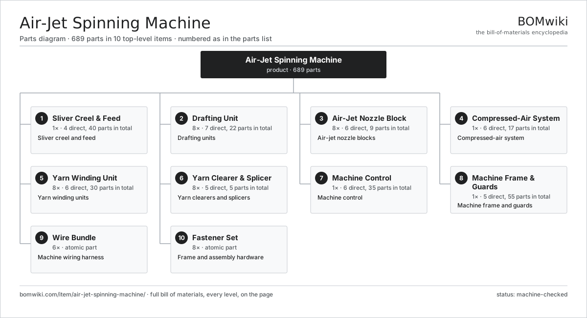
| # | Part | Qty | What it does |
|---|---|---|---|
| 1 | Sliver Creel & Feed 4 parts | 1× | Sliver creel and feed |
| 2 | Drafting Unit 7 parts | 8× | Drafting units |
| 3 | Air-Jet Nozzle Block 6 parts | 8× | Air-jet nozzle blocks |
| 4 | Compressed-Air System 6 parts | 1× | Compressed-air system |
| 5 | Yarn Winding Unit 6 parts | 8× | Yarn winding units |
| 6 | Yarn Clearer & Splicer 5 parts | 8× | Yarn clearers and splicers |
| 7 | Machine Control 6 parts | 1× | Machine control |
| 8 | Machine Frame & Guards 5 parts | 1× | Machine frame and guards |
| 9 | Wire Bundle | 6× | Machine wiring harness |
| 10 | Fastener Set | 8× | Frame and assembly hardware |
3D model
No 3D model yet. Have a CAD file of this? Add a 3D model. STL renders right on this page; STEP, FreeCAD, and OpenSCAD sources are welcome too (openly licensed, like all 3D models on BOMwiki).
Build & assembly graph
expand / collapse · shared sub-assemblies converge · links to related products · est. labourTap an assembly to expand/collapse · tap a part to open it · use “Open page” for any node · drag to pan, scroll to zoom.
Bill of materials for Air-Jet Spinning Machine
10 top-level lines · 67 rows shown · 689 parts total · indented to 3 levels| # | Item / sub-assembly | Part no. | Qty/assy | Ext. qty | Parts | Type |
|---|---|---|---|---|---|---|
| 1 | Sliver Creel & Feed 4 parts | air-jet-spinning-machine-creel | 1× | 1 | 40 | assembly |
| 1.1 | Sliver Can Stand | air-jet-spinning-machine-can-stand | 16× | 16 | · | part |
| 1.2 | Sliver Guide | air-jet-spinning-machine-sliver-guide | 8× | 8 | · | part |
| 1.3 | Feed Roller | air-jet-spinning-machine-feed-roller | 8× | 8 | · | part |
| 1.4 | Sliver Stop-Motion Sensor | air-jet-spinning-machine-stop-sensor | 8× | 8 | · | part |
| 2 | Drafting Unit 7 parts | air-jet-spinning-machine-drafting | 8× | 8 | 22 | assembly |
| 2.1 | Bottom Drafting Roller | air-jet-spinning-machine-bottom-roller | 4× | 32 | · | part |
| 2.2 | Top Pressure Roller | air-jet-spinning-machine-top-roller | 4× | 32 | · | part |
| 2.3 | Drafting Apron | air-jet-spinning-machine-apron | 2× | 16 | · | part |
| 2.4 | Fiber Condenser | air-jet-spinning-machine-condenser | 1× | 8 | · | part |
| 2.5 | Pneumatic Loading Arm | air-jet-spinning-machine-loading-arm | 1× | 8 | · | part |
| 2.6 | Helical Gear Pair | gear-pair | 2× | 16 | · | part |
| 2.7 | Ball Bearing | ball-bearing | 8× | 64 | · | part |
| 3 | Air-Jet Nozzle Block 6 parts | air-jet-spinning-machine-nozzle-block | 8× | 8 | 9 | assembly |
| 3.1 | First Air Nozzle | air-jet-spinning-machine-first-nozzle | 1× | 8 | · | part |
| 3.2 | Second Air Nozzle | air-jet-spinning-machine-second-nozzle | 1× | 8 | · | part |
| 3.3 | Hollow Spindle Tube | air-jet-spinning-machine-spindle-tube | 1× | 8 | · | part |
| 3.4 | Tangential Jet Orifice | air-jet-spinning-machine-jet-orifice | 4× | 32 | · | part |
| 3.5 | Delivery Roller | air-jet-spinning-machine-delivery-roller | 1× | 8 | · | part |
| 3.6 | O-Ring Set | oring-set | 1× | 8 | · | part |
| 4 | Compressed-Air System 6 parts | air-jet-spinning-machine-air-system | 1× | 1 | 17 | assembly |
| 4.1 | Air Receiver Tank | air-jet-spinning-machine-air-receiver | 1× | 1 | · | part |
| 4.2 | Air Dryer | air-jet-spinning-machine-air-dryer | 1× | 1 | · | part |
| 4.3 | Pressure Regulator | air-jet-spinning-machine-regulator | 4× | 4 | · | part |
| 4.4 | Distribution Manifold | air-jet-spinning-machine-manifold | 1× | 1 | · | part |
| 4.5 | Nozzle Supply Valve | air-jet-spinning-machine-air-valve | 8× | 8 | · | part |
| 4.6 | Pressure Sensor | pressure-sensor | 2× | 2 | · | part |
| 5 | Yarn Winding Unit 6 parts | air-jet-spinning-machine-winding | 8× | 8 | 30 | assembly |
| 5.1 | Take-Up Drum | air-jet-spinning-machine-take-up-drum | 1× | 8 | · | part |
| 5.2 | Traverse Guide | air-jet-spinning-machine-traverse | 1× | 8 | · | part |
| 5.3 | Package Cradle | air-jet-spinning-machine-package-cradle | 1× | 8 | · | part |
| 5.4 | Yarn Tension Device | air-jet-spinning-machine-tension-device | 1× | 8 | · | part |
| 5.5 | Servo Motor 4 parts | servo-motor | 1× | 8 | 24 | assembly |
| 5.5.1 | Stator Assembly 3 parts + deeper › | stator-assembly | 1× | 8 | 3 | assembly |
| 5.5.2 | Rotor Assembly 4 parts + deeper › | rotor-assembly | 1× | 8 | 19 | assembly |
| 5.5.3 | Encoder | encoder | 1× | 8 | · | part |
| 5.5.4 | Motor Housing | motor-housing | 1× | 8 | · | part |
| 5.6 | Ball Bearing | ball-bearing | 2× | 16 | · | part |
| 6 | Yarn Clearer & Splicer 5 parts | air-jet-spinning-machine-clearer | 8× | 8 | 5 | assembly |
| 6.1 | Optical Clearer Head | air-jet-spinning-machine-clearer-head | 1× | 8 | · | part |
| 6.2 | Yarn Cutter | air-jet-spinning-machine-cutter | 1× | 8 | · | part |
| 6.3 | Pneumatic Splicer | air-jet-spinning-machine-splicer | 1× | 8 | · | part |
| 6.4 | Suction Pickup Arm | air-jet-spinning-machine-suction-arm | 1× | 8 | · | part |
| 6.5 | Bare PCB | pcb-bare | 1× | 8 | · | part |
| 7 | Machine Control 6 parts | air-jet-spinning-machine-control | 1× | 1 | 35 | assembly |
| 7.1 | Main Controller 4 parts | air-jet-spinning-machine-controller | 1× | 1 | 7 | assembly |
| 7.1.1 | Bare PCB | pcb-bare | 1× | 1 | · | part |
| 7.1.2 | Microcontroller | mcu | 1× | 1 | · | part |
| 7.1.3 | SMD Passive (R/C/L) | smd-passives | 1× | 1 | · | part |
| 7.1.4 | Connector | connector | 4× | 4 | · | part |
| 7.2 | LCD Panel | lcd-panel | 1× | 1 | · | part |
| 7.3 | Power Supply | power-supply | 1× | 1 | · | part |
| 7.4 | Microcontroller | mcu | 8× | 8 | · | part |
| 7.5 | Relay | relay | 6× | 6 | · | part |
| 7.6 | Connector | connector | 12× | 12 | · | part |
| 8 | Machine Frame & Guards 5 parts | air-jet-spinning-machine-frame | 1× | 1 | 55 | assembly |
| 8.1 | Welded Base Frame | air-jet-spinning-machine-base-frame | 1× | 1 | · | part |
| 8.2 | End Drive Gearbox 4 parts | air-jet-spinning-machine-end-gearbox | 2× | 2 | 14 | assembly |
| 8.2.1 | Gearbox Housing | gearbox-housing | 1× | 2 | · | part |
| 8.2.2 | Helical Gear Pair | gear-pair | 3× | 6 | · | part |
| 8.2.3 | Ball Bearing | ball-bearing | 6× | 12 | · | part |
| 8.2.4 | Oil Seal | oil-seal | 4× | 8 | · | part |
| 8.3 | Position Guard | air-jet-spinning-machine-guard | 16× | 16 | · | part |
| 8.4 | Sheet Metal Panel | sheet-panel | 8× | 8 | · | part |
| 8.5 | Drive Belt | drive-belt | 2× | 2 | · | part |
| 9 | Wire Bundle | wire-bundle | 6× | 6 | · | part |
| 10 | Fastener Set | fastener-set | 8× | 8 | · | part |
Related products
same domain, ranked by shared parts Industrial Quilting Machine
1,090 parts · shares 8 with this page
Jet Dyeing Machine
263 parts · shares 8 with this page
Jigger Dyeing Machine
276 parts · shares 8 with this page
POY Spinning Machine
2,277 parts · shares 8 with this page
Industrial Quilting Machine
1,090 parts · shares 8 with this page
Jet Dyeing Machine
263 parts · shares 8 with this page
Jigger Dyeing Machine
276 parts · shares 8 with this page
POY Spinning Machine
2,277 parts · shares 8 with this page
 Textile Stenter Frame
1,683 parts · shares 8 with this page
Spunlace Nonwoven Line
1,735 parts · shares 7 with this page
Textile Stenter Frame
1,683 parts · shares 8 with this page
Spunlace Nonwoven Line
1,735 parts · shares 7 with this page
Sourcing: possible vendors
Browse the supplier directory → Prices, MOQ, and lead times are algorithmic estimates, not quotes, and not claims about these companies. Company mappings are curated by keyword; est. price band $10k–$1M. How estimates work| Vendor | HQ | Specialty | MOQ | Lead time |
|---|---|---|---|---|
|
🇨🇭Rieter
rieter.com ↗
|
Winterthur, CH | Spinning machinery | 10 units | 14–24 wks |
| truetzschler.com ↗ | Mönchengladbach, DE | Textile machinery | 10 units | 14–24 wks |
|
🇧🇪Picanol
picanol.be ↗
|
Ypres, BE | Weaving machines | 10 units | 14–24 wks |
| karlmayer.com ↗ | Obertshausen, DE | Warp knitting machines | 10 units | 14–24 wks |
|
🇨🇭Saurer
saurer.com ↗
|
Arbon, CH | Spinning & embroidery | 10 units | 14–24 wks |
885-word article