Roving Frame
ProductOverview
A roving frame, also called a speed frame, is the last step before ring spinning. The draw frame delivers a thick, even sliver, but that sliver is far too heavy to feed straight into a ring frame and has no twist to hold it together. The roving frame bridges the gap: it drafts the sliver down to a thin strand called roving, perhaps a tenth of the weight per metre, puts in just enough twist to give that thin strand some strength, and winds it onto a bobbin in a form the ring frame can draw off smoothly.
The amount of twist is the delicate part. Too little and the roving falls apart in handling and in the ring-frame creel. Too much and the ring frame cannot draft it out again. So the roving carries only a fraction of a turn per inch, enough to survive the trip to the next machine and no more.
Drafting the sliver
Sliver from the cans in the overhead Sliver Creel & Feed feeds down into a Drafting Unit unit, one per spindle. This is a longer, higher draft than the draw frame uses because the strand is being thinned much more. The middle of the draft zone uses a Double Apron Pair, two short belts that grip the fibers as they speed up between rollers. The strand here is so thin that without the aprons the shorter fibers would float free and drift, making the roving uneven. The Bottom Drafting Roller front pair runs fastest and pulls the strand out to its final fineness, while Fiber Condenser guides keep the thin ribbon from spreading and shedding edge fibers.
Twisting with the flyer
Once drafted, the strand has no strength on its own, so the Flyer & Twisting puts in twist. The flyer is a U-shaped fork that spins fast on the Spindle above the bobbin. The roving enters the Flyer Top Entry eye, runs down the inside of one hollow Hollow Flyer Leg, and reaches the Presser Arm at the foot, which wraps it onto the bobbin. Each revolution of the flyer puts one turn of twist into the length of roving between the front roller and the flyer top, and the spin happens before the roving is wound, so the strand arriving at the bobbin already holds together.
Building the bobbin
Winding the roving onto the bobbin is harder than it looks. The flyer turns at constant speed but the bobbin diameter grows as it fills, so the wind-on speed has to fall through the build or the roving would be wound tighter and tighter. The Bobbin Rail & Building Motion handles this with a building motion: a Cone Drum Drive drive steadily changes the bobbin speed as the diameter grows, while the rail moves up and down in strokes that shorten layer by layer, building the package as a clean taper. The Builder Motion Gearbox gearbox ties all this together so the bobbin builds without soft layers or ridges that would later cause uneven feed at the ring frame.
Automatic doffing
A roving frame may carry a hundred and fifty spindles, and doffing them by hand at every full bobbin was slow heavy work. The Automatic Doffer does it automatically. When the bobbins are full the machine stops, the Doffer Gripper Rail drops over them, the Bobbin Gripper jaws clamp every tube, and the rail lifts the whole row off at once. Empty tubes are set from the magazine onto the spindles and the full bobbins go onto a transport belt toward the ring-frame creel. The machine restarts in a minute or two instead of the long stop that hand doffing took.
Drive, control and frame
The Main Drive & Gearing turns the flyers, the roller line and the building motion from one main motor through the headstock gearbox, with a long Tin Roller Shaft shaft carrying drive to every spindle. The Machine Control cabinet sets flyer speed, draft and twist from a touchscreen, runs the building and doffing cycles, and logs production. The whole machine sits on a long welded Machine Frame & Guards with the spindle rows, headstock and bobbin rail held in alignment, and interlocked guards over the spinning flyers.
Materials and use
The drafting rollers are case-hardened steel with rubber top cots, the spindles and lift screws are alloy steel for fatigue life under constant reversal, and the frame is welded structural steel for length stiffness. The flyers are light alloy so they can spin fast without too much load on the spindle bearings.
Every short-staple spinning mill that runs ring frames runs roving frames ahead of them, one roving frame feeding several ring frames. The roving it delivers sets how evenly the ring frame can draft, so the package build and the twist level are watched as carefully as the count. Mills that have moved to rotor or air-jet spinning skip the roving stage, since those processes feed straight from sliver, but for ring-spun yarn the roving frame remains a fixed step in the line.
Roving Frame parts and their functions
10 top-level parts · 619 parts in total · full bill of materials below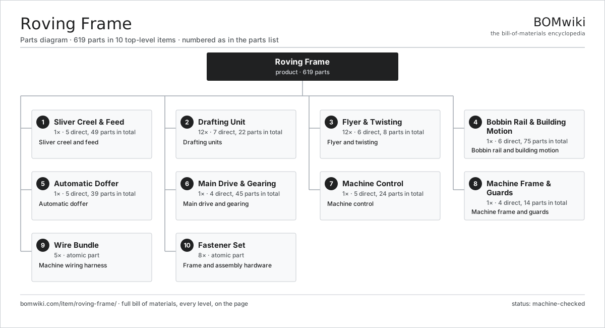
| # | Part | Qty | What it does |
|---|---|---|---|
| 1 | Sliver Creel & Feed 5 parts | 1× | Sliver creel and feed |
| 2 | Drafting Unit 7 parts | 12× | Drafting units |
| 3 | Flyer & Twisting 6 parts | 12× | Flyer and twisting |
| 4 | Bobbin Rail & Building Motion 6 parts | 1× | Bobbin rail and building motion |
| 5 | Automatic Doffer 5 parts | 1× | Automatic doffer |
| 6 | Main Drive & Gearing 4 parts | 1× | Main drive and gearing |
| 7 | Machine Control 5 parts | 1× | Machine control |
| 8 | Machine Frame & Guards 4 parts | 1× | Machine frame and guards |
| 9 | Wire Bundle | 5× | Machine wiring harness |
| 10 | Fastener Set | 8× | Frame and assembly hardware |
3D model
No 3D model yet. Have a CAD file of this? Add a 3D model. STL renders right on this page; STEP, FreeCAD, and OpenSCAD sources are welcome too (openly licensed, like all 3D models on BOMwiki).
Build & assembly graph
expand / collapse · shared sub-assemblies converge · links to related products · est. labourTap an assembly to expand/collapse · tap a part to open it · use “Open page” for any node · drag to pan, scroll to zoom.
Bill of materials for Roving Frame
10 top-level lines · 75 rows shown · 619 parts total · indented to 3 levels| # | Item / sub-assembly | Part no. | Qty/assy | Ext. qty | Parts | Type |
|---|---|---|---|---|---|---|
| 1 | Sliver Creel & Feed 5 parts | roving-frame-creel | 1× | 1 | 49 | assembly |
| 1.1 | Creel Guide Roller | roving-frame-creel-roller | 12× | 12 | · | part |
| 1.2 | Sliver Trumpet | roving-frame-sliver-trumpet | 12× | 12 | · | part |
| 1.3 | Feed Stop-Motion Sensor | roving-frame-creel-stop | 12× | 12 | · | part |
| 1.4 | Creel Frame | roving-frame-creel-frame | 1× | 1 | · | part |
| 1.5 | Ball Bearing | ball-bearing | 12× | 12 | · | part |
| 2 | Drafting Unit 7 parts | roving-frame-drafting | 12× | 12 | 22 | assembly |
| 2.1 | Bottom Drafting Roller | roving-frame-bottom-roller | 4× | 48 | · | part |
| 2.2 | Top Pressure Roller | roving-frame-top-roller | 4× | 48 | · | part |
| 2.3 | Double Apron Pair | roving-frame-apron-pair | 1× | 12 | · | part |
| 2.4 | Fiber Condenser | roving-frame-condenser | 2× | 24 | · | part |
| 2.5 | Roller Weighting Arm | roving-frame-weighting-arm | 1× | 12 | · | part |
| 2.6 | Helical Gear Pair | gear-pair | 2× | 24 | · | part |
| 2.7 | Ball Bearing | ball-bearing | 8× | 96 | · | part |
| 3 | Flyer & Twisting 6 parts | roving-frame-flyer | 12× | 12 | 8 | assembly |
| 3.1 | Flyer Body | roving-frame-flyer-body | 1× | 12 | · | part |
| 3.2 | Hollow Flyer Leg | roving-frame-flyer-leg | 2× | 24 | · | part |
| 3.3 | Presser Arm | roving-frame-presser-arm | 1× | 12 | · | part |
| 3.4 | Flyer Top Entry | roving-frame-flyer-top | 1× | 12 | · | part |
| 3.5 | Spindle | roving-frame-spindle | 1× | 12 | · | part |
| 3.6 | Ball Bearing | ball-bearing | 2× | 24 | · | part |
| 4 | Bobbin Rail & Building Motion 6 parts | roving-frame-bobbin-rail | 1× | 1 | 75 | assembly |
| 4.1 | Bobbin Rail | roving-frame-rail | 1× | 1 | · | part |
| 4.2 | Roving Bobbin | roving-frame-bobbin | 12× | 12 | · | part |
| 4.3 | Builder Motion Gearbox 4 parts | roving-frame-builder-motion | 1× | 1 | 11 | assembly |
| 4.3.1 | Gearbox Housing | gearbox-housing | 1× | 1 | · | part |
| 4.3.2 | Helical Gear Pair | gear-pair | 4× | 4 | · | part |
| 4.3.3 | Ball Bearing | ball-bearing | 4× | 4 | · | part |
| 4.3.4 | Oil Seal | oil-seal | 2× | 2 | · | part |
| 4.4 | Rail Lift Screw | roving-frame-lift-screw | 2× | 2 | · | part |
| 4.5 | Cone Drum Drive | roving-frame-cone-drum | 1× | 1 | · | part |
| 4.6 | Servo Motor 4 parts | servo-motor | 2× | 2 | 24 | assembly |
| 4.6.1 | Stator Assembly 3 parts + deeper › | stator-assembly | 1× | 2 | 3 | assembly |
| 4.6.2 | Rotor Assembly 4 parts + deeper › | rotor-assembly | 1× | 2 | 19 | assembly |
| 4.6.3 | Encoder | encoder | 1× | 2 | · | part |
| 4.6.4 | Motor Housing | motor-housing | 1× | 2 | · | part |
| 5 | Automatic Doffer 5 parts | roving-frame-doffer | 1× | 1 | 39 | assembly |
| 5.1 | Doffer Gripper Rail | roving-frame-doffer-rail | 1× | 1 | · | part |
| 5.2 | Bobbin Gripper | roving-frame-gripper | 12× | 12 | · | part |
| 5.3 | Empty Tube Magazine | roving-frame-tube-magazine | 1× | 1 | · | part |
| 5.4 | Bobbin Transport Belt | roving-frame-transport-belt | 1× | 1 | · | part |
| 5.5 | Servo Motor 4 parts | servo-motor | 1× | 1 | 24 | assembly |
| 5.5.1 | Stator Assembly 3 parts + deeper › | stator-assembly | 1× | 1 | 3 | assembly |
| 5.5.2 | Rotor Assembly 4 parts + deeper › | rotor-assembly | 1× | 1 | 19 | assembly |
| 5.5.3 | Encoder | encoder | 1× | 1 | · | part |
| 5.5.4 | Motor Housing | motor-housing | 1× | 1 | · | part |
| 6 | Main Drive & Gearing 4 parts | roving-frame-drive | 1× | 1 | 45 | assembly |
| 6.1 | Main Drive Motor 3 parts | roving-frame-main-motor | 1× | 1 | 24 | assembly |
| 6.1.1 | Stator Assembly 3 parts + deeper › | stator-assembly | 1× | 1 | 3 | assembly |
| 6.1.2 | Rotor Assembly 4 parts + deeper › | rotor-assembly | 1× | 1 | 19 | assembly |
| 6.1.3 | Ball Bearing | ball-bearing | 2× | 2 | · | part |
| 6.2 | Headstock Gearbox 4 parts | roving-frame-headstock-gearbox | 1× | 1 | 18 | assembly |
| 6.2.1 | Gearbox Housing | gearbox-housing | 1× | 1 | · | part |
| 6.2.2 | Helical Gear Pair | gear-pair | 5× | 5 | · | part |
| 6.2.3 | Ball Bearing | ball-bearing | 8× | 8 | · | part |
| 6.2.4 | Oil Seal | oil-seal | 4× | 4 | · | part |
| 6.3 | Tin Roller Shaft | roving-frame-tin-roller | 1× | 1 | · | part |
| 6.4 | Drive Belt | drive-belt | 2× | 2 | · | part |
| 7 | Machine Control 5 parts | roving-frame-control | 1× | 1 | 24 | assembly |
| 7.1 | Main Controller 4 parts | roving-frame-controller | 1× | 1 | 7 | assembly |
| 7.1.1 | Bare PCB | pcb-bare | 1× | 1 | · | part |
| 7.1.2 | Microcontroller | mcu | 1× | 1 | · | part |
| 7.1.3 | SMD Passive (R/C/L) | smd-passives | 1× | 1 | · | part |
| 7.1.4 | Connector | connector | 4× | 4 | · | part |
| 7.2 | LCD Panel | lcd-panel | 1× | 1 | · | part |
| 7.3 | Power Supply | power-supply | 1× | 1 | · | part |
| 7.4 | Relay | relay | 5× | 5 | · | part |
| 7.5 | Connector | connector | 10× | 10 | · | part |
| 8 | Machine Frame & Guards 4 parts | roving-frame-frame | 1× | 1 | 14 | assembly |
| 8.1 | Machine Base | roving-frame-base | 1× | 1 | · | part |
| 8.2 | Spindle Support Rail | roving-frame-spindle-rail | 1× | 1 | · | part |
| 8.3 | Flyer Guard | roving-frame-guard | 6× | 6 | · | part |
| 8.4 | Sheet Metal Panel | sheet-panel | 6× | 6 | · | part |
| 9 | Wire Bundle | wire-bundle | 5× | 5 | · | part |
| 10 | Fastener Set | fastener-set | 8× | 8 | · | part |
Related products
same domain, ranked by shared parts Automatic Fabric Cutting Machine
1,695 parts · shares 6 with this page
Automatic Winding Machine
288 parts · shares 6 with this page
Automatic Fabric Cutting Machine
1,695 parts · shares 6 with this page
Automatic Winding Machine
288 parts · shares 6 with this page
 Industrial Quilting Machine
1,090 parts · shares 6 with this page
Jet Dyeing Machine
263 parts · shares 6 with this page
Jigger Dyeing Machine
276 parts · shares 6 with this page
Industrial Quilting Machine
1,090 parts · shares 6 with this page
Jet Dyeing Machine
263 parts · shares 6 with this page
Jigger Dyeing Machine
276 parts · shares 6 with this page
Sourcing: possible vendors
Browse the supplier directory → Prices, MOQ, and lead times are algorithmic estimates, not quotes, and not claims about these companies. Company mappings are curated by keyword; est. price band $10k–$1M. How estimates work| Vendor | HQ | Specialty | MOQ | Lead time |
|---|---|---|---|---|
|
🇨🇭Rieter
rieter.com ↗
|
Winterthur, CH | Spinning machinery | 10 units | 14–24 wks |
| truetzschler.com ↗ | Mönchengladbach, DE | Textile machinery | 10 units | 14–24 wks |
|
🇧🇪Picanol
picanol.be ↗
|
Ypres, BE | Weaving machines | 10 units | 14–24 wks |
| karlmayer.com ↗ | Obertshausen, DE | Warp knitting machines | 10 units | 14–24 wks |
|
🇨🇭Saurer
saurer.com ↗
|
Arbon, CH | Spinning & embroidery | 10 units | 14–24 wks |
861-word article